Manjunath et al. World Journal of Engineering Research and Technology
COMPARATIVE STUDY OF EMISSION CHARACTERISTICS FOR A
MODIFIED CAM IN CARBURETTOR AND MPFI ENGINE
Manjunath Gowda M. R*1, Harish Kumar R2 and N. S. Venkatesh Guptha3
1
Research Scholar, Dept. of Mechanical Engg, VTU-RRC, Belgaum, Karanataka, India.
2
Professor of Mechanical Engineering, S.S.I.T, Tumkur, Karanataka, India.
3
Associate Prof of Mechanical Engineering S.I.T, Tumkur, Karanatak, India.
Article Received on 24/02/2017 Article Revised on 17/03/2017 Article Accepted on 06/04/2017
ABSTRACT
An internal combustion engine (ICE) is a heat engine where
the combustion of a fuel occurs with an oxidizer (usually air) in a
combustion chamber that is an integral part of the working fluid flow
circuit. In an internal combustion engine the expansion of the
high-temperature and high-pressure gases produced by combustion apply
direct force to some component of the engine. The comparative study of Emission
Characteristics has been made at different profiles of modified Cam for Carburettor and
MPFI Engine An Emission qualities have been learned at 3 unique profiles of cam for
carburettor and MPFI Engine and a significant reduction in discharges have been recorded in
MPFI Engine is contrasted with carburettor Engine.
KEYWORDS: MPFI Engine, Carburettor, Variable Valve timing, TRI-LOBED-CAM, Valve dynamics.
INTRODUCTION
In conventional engine design, the camshaft uses a fixed or variable cam profile to achieve a
reasonable compromise between idle speed stability, fuel economy, and torque performance.
Significant improvements in engine performance can be achieved through individual control
of the valve timing.
*Corresponding Author Manjunath Gowda M. R.
Research Scholar, Dept. of
Mechanical Engg,
VTU-RRC, Belgaum, Karanataka,
India.
World Journal of Engineering Research and Technology
WJERT
So In internal combustion engines, Variable valve timing (VVT), also known as Variable
valve actuation (VVA), is a generalized term used to describe any mechanism or method that
can alter the shape or timing of a valve lift event within an internal combustion engine. VVT
allows the lift, duration or timing (in various combinations) of the intake and/or exhaust
valves to be changed while the engine is in operation.
The automotive industry has been under continued pressure to improve the fuel efficiency
owing to stringent pollution norms, global warming and rising petroleum prices. The largest
part of most combustion gas is nitrogen (N2), water vapor (H2O) and carbon dioxide (CO2)
these are not toxic. A relatively small part of combustion gas is undesirable noxious or toxic
substances, such as carbon monoxide (CO) from incomplete combustion, hydrocarbons
(properly indicated as CxHy, but typically shown simply as "HC" on emissions-test slips)
from unburnt fuel, nitrogen oxides (NOx) from excessive combustion temperatures,
and particulate matter (mostly soot).
Exhaust gas or flue gas is emitted as a result of the combustion of fuels such as natural
gas, gasoline, petrol, biodiesel blends, fuel, fuel or coal. According to the type of engine, it is
discharged into the atmosphere through an exhaust pipe, flue gas stack or propelling nozzle.
Fuel (hydrogen, carbon, sulphur) + Air (nitrogen, oxygen) = Carbon dioxide + water vapour
+ oxygen + carbon monoxide + hydrocarbon + oxides of nitrogen + sulphur oxides.
Carbon monoxide (CO) - A product of incomplete combustion, concentration of the exhaust
in percent of the total sample. Partially Burned Petrol, This is the petrol that has combusted,
but not completely. This gas is formed in the cylinders when there is incomplete combustion
and an excess of fuel. Therefore excessive CO contents are always a sign of an overly rich
mixture preparation. (The CO should have become CO2 but did not have the time or enough
O2 to become real CO2 so it is exhausted as CO instead.) CO is highly poisonous odorless
gas. Carbon monoxide reduces the blood's ability to carry oxygen; overexposure (carbon
monoxide poisoning) may be fatal. Carbon Monoxide poisoning is a killer in high
concentrations.
Hydrocarbons - A class of burned or partially burned fuel, hydrocarbons are toxins.
Hydrocarbons are a major contributor to smog, which can be a major problem in urban areas.
amount of unburned fuel due to incomplete combustion exiting through the exhaust.
Prolonged exposure to hydrocarbons contributes to asthma, liver disease, lung disease,
and cancer.
Carbon dioxide is a greenhouse gas. Motor vehicle CO2 emissions are part of the
anthropogenic contribution to the growth of CO2 concentrations in the atmosphere which is
causing climate change. Concentration of the exhaust in percent of the total sample. =
Completely Burned Petrol, represents how well the air/fuel mixture is burned in the engine
(efficiency). This gas gives a direct indication of combustion efficiency. This is due to
improved gas flow resulting in better combustion efficiency.
Particulate matter – Soot or smoke made up of particles in the micrometer size range,
Particulate matter causes negative health effects, including but not limited to respiratory
disease and cancer. An instrument exhaust gas analyzer is used to find the emissions CO, HC
and C02.
OBJECTIVE
The proposed new design of the valve actuator mechanism is expected to overcome the
inherent limitations of the fixed cam valve actuation mechanisms as well as the deficiencies
of the VVT cam systems marginally.
A new “TRI-LOBED-CAM” mechanism used in conjunction with a conventional cam
operating mechanism that axially shifts the camshaft through a small displacement depending
on the operating conditions of the engine
The emission characteristics for carburettor and MPFI engine is studied at 3 different
locations of the modified CAM where the valve movement is varied and controlled by using
the modified CAM Shaft.
Fig 1: Tri Lobed CAM.
Modified Camshaft
Fig 2: MODIFIED Iso-metric view of CAM SHAFT.
The changed camshaft conveys one decreased cam for every valve to be worked. The
camshaft is driven by the crankshaft by method for timing gears. It comprises of round and
hollow bar with various decreased flaps projecting from it, one for every valve. The profile of
the altered camshaft is upgrade with falt surface to tapered(slope) shape.
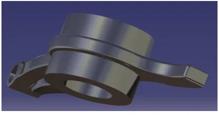
Modified Rocker
Fig 3: MODIFIED ROCKER with Edges.
The modified rocker arm conveys radial movement from the cam lobe into linear movement
at the poppet valve to open it. One end is raised and lowered by a rotating of the camshaft
that is reduced their width while the other end acts on the valve stem. The modified rocker
Emission Characteristics
Emissions of many air pollutants have been shown to have variety of negative
effects on public health and the natural environment.
Fuel (hydrogen, carbon, sulphur) + Air (nitrogen, oxygen) = Carbon dioxide + water vapour
+ oxygen + carbon monoxide + hydrocarbon + oxides of nitrogen + sulphur oxides.
A standard 5 series exhaust gas analyzer has been used to measure the exhaust emissions
from the engine. The instrument which is used to find the emissions is shown below
Fig 4: Emission Testing Machine.
An exhaust gas analyzer or exhaust CO analyzer is an instrument for the measurement of
carbon monoxide among other gases in the exhaust, caused by an incorrect combustion.
Measuring the exhaust gas is an excellent way to optimize fuel and air input. Efficient
combustion also reduces emission of pollutants such as nitric oxide (NO), nitrogen dioxide
(NO2), sulfur dioxide (SO2), and particulate matter. A gas analyzer will help measure various
gas pollutants in the exhaust for environmental reasons.
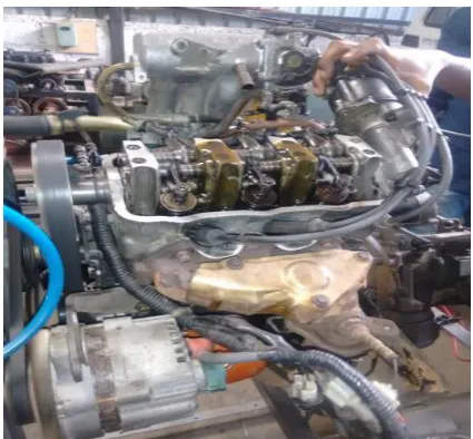
Modified Cam Shaft with rocker is placed in the engine head and emission of CO, HC and
CO2 is noted for different profiles of CAM ploted wrt to valve movement.
Emission characteristics for MPFI Engine is studied at 3 different locations of Cam Shaft
which is shown below.
Emission characteristics at 3 different locations for 80 & 90 degree of taper turn in CAM for Carburettor engine
For 80 of Taper turn in CAM
Table 5: Exhaust emission at Maximum, Centre and Minimum for 80 of Taper turn in CAM in carburettor engine.
SL NO
Diameter of the CAM (mm) Valve lift in mm Exhaust Emission of CO Exhaust Emission of HC Exhaust Emission of CO2
1 35.74(Maximum) 7.319 3.640 501 11.24
2 34.62(Centre) 6.022 2.291 402 8.02
3 33.6(Minimum) 4.396 1.680 314 6.13
Table 6: Exhaust emission at Maximum, Centre and Minimum for 80 of Taper turn in CAM in MPFI engine.
SL NO
Diameter of the CAM (mm)
Valve lift in mm Exhaust Emission of CO Exhaust Emission of HC Exhaust Emission of CO2
1 35.74(Maximum) 7.319 0.648 346 11.62
2 34.62(Centre) 6.022 0.445 90 10.84
Exhaust emission at Maximum, Centre and Minimum for 80 of Taper turn in CAM in MPFI engine
Fig 6: Valve Movement V/S Exhaust emission of CO
When the rocker is placed on the maximum, centre and minimum diameter of the Cam Shaft
then the valve movement is decreased so that the exhaust emission CO is reduced.
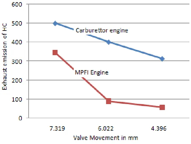
Fig 7: Valve Movement V/S Exhaust emission of HC
When the rocker is placed on the maximum, centre and minimum diameter of the Cam Shaft
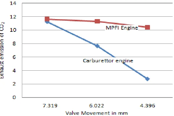
Fig 8: Valve Movement V/S Exhaust emission of CO2
When the rocker is placed on the maximum, centre and minimum diameter of the Cam Shaft
then the valve movement is decreased so that the exhaust emission CO2 is reduced.
For 90 of Taper turn in CAM
Table 7: Exhaust emission at Maximum, Centre and Minimum for 90 of Taper turn in CAM in carburettor engine.
SL NO
Diameter of the CAM (mm)
Valve lift in mm Exhaust Emission of CO Exhaust Emission of HC Exhaust Emission of CO2
1 35.74(Maximum) 7.319 3.640 501 11.24
2 34.47(Centre) 5.925 1.863 491 7.65
3 33.45(Minimum) 3.961 1.460 103 2.77
Table 8: Exhaust emission at Maximum, Centre and Minimum for 90 of Taper turn in CAM in MPFI engine.
SL NO
Diameter of the CAM (mm)
Valve lift in mm Exhaust Emission of CO Exhaust Emission of HC Exhaust Emission of CO2
1 35.74(Maximum) 7.319 0.648 346 11.62
2 34.47(Centre) 5.925 0.398 136 11.30
Fig 10: Valve Movement V/S Exhaust emission of CO
Fig 11: Valve Movement V/S Exhaust emission of HC
The above figures clearly point out the exhaust gas emissions are reduced for the MPFI
engine is compared to the carburettor engine with the use of flexible valve actuation
mechanism.
CONCLUSION
A fully flexible valve actuation system of 80 and 90 taper turn in CAM is conceived and
designed. So as to give variable valve displacement, flexibility and can be controlled.
Emission characteristics for a modified cam have been studied at variable valve displacement
depending on the operating conditions of the engine viz., minimum value displacement at
lean loads/low engine speeds, medium valve displacement at intermediate loads and
maximum valve displacement at high loads/high engine speeds.
Emission characteristics can be also controlled since the fuel efficiency is increased. So the
emission is reduced at 3 different locations of the CAM Shaft as the valve movement is
varied and controlled by using the modified CAM Shaft.
REFERENCES
1. L. Mianzo and H. Peng, “Output feedback H preview control of an electromechanical
valve actuator,” IEEE Trans.Control Syst. Technol., Apr. 2007; 15(3): 428–437.
2. Eid Mohamed “Modeling and performance evaluation of an electromechanical valve
actuator for a camless IC engine”, International Journal of Energy and environment,
2012; 3(2): 275-294.
3. Mr.Paresh K. Kasundra, Prof. Ashish V. Gohil, “Performance Test of CI Engine with
Different Vegetable Oil as a Fuel” International Journal of Engineering Trends and
Technology, 2011; 2(3).
4. S. Naga Sarada, M.Shailaja, A.V. Sita Rama Raju, K. Kalyani Radha “Optimization of
injection pressure for a compression ignition engine with cotton seed oil as an alternate
fuel” International Journal of Engineering, Science and Technology, 2010; 2(6): 142-149.
5. Kern Y. Kang, Je H. Baek “Turbulence characteristics of tumble flow in a four-valve
engine”. Experimental Thermal and Fluid Science, 1998; 18: 231-243.
6. G Lakshmi Narayana Rao, S Sampath, K Rajagopal “Experimental Studies on the
Combustion and Emission Characteristics of a Diesel Engine Fuelled with Used Cooking
Oil Methyl Ester and its Diesel Blends” World Academy of Science, Engineering and
7. J. Tsai, C. R. Koch, and M. Saif, “Cycle adaptive feedforward approach control of an
electromagnetic valve actuator,” in Proc. 47th IEEE Conf. Decision Control, Cancun,
Mexico, 2008: 5698–5703.
8. Kwanhee Choi, Hyungmin Lee, In Goo Hwang, Cha-Lee Myung and Simsoo Park, “
Effects of various intake valve timings and spark timings on combustion, cyclic THC and
NOX emissions during cold start phase with idle operation in CVVT engine”, Journal of
Mechanical Science and Technology, 2008; 22: 2254-2262.
9. Liao Shiyong, Jiang Deming, Gao Jian and Zeng Ke “Effects of different frequency
components in turbulence on accelerating turbulent premixed Combustion”Proceedings
of the Institution of Mechanical Engineers, Part D: Journal of Automobile Engineering,