Volume-5 Issue-2
International Journal of Intellectual Advancements
and Research in Engineering Computations
To increase the efficiency of the boiler by optimizing the combustion.
Mr. M.Sugumar1, P.Gokul2, S.Gokul2, S.Hariprabhakaran2, M.Prabhu2. 1
Assistant Professor, 2UG Students,
Department of Mechanical Engineering, Nandha Engineering College, Erode-52, Tamil Nadu, India.
[email protected], [email protected]
Abstract
Increases in fuel costs, power demands, and emissions regulations, as well as the need to reduce power generation costs, have forced the electric utility industry to improve combustion efficiency. The Smart Process Combustion Optimization solution increases boiler efficiency while maintaining emissions, decreasing loss on ignition, and reducing a number of other plant operating costs. The Combustion Optimization solution is a quick, inexpensive way to properly distribute the fuel and air supply for control of NOx and manage the fine line between reduced flame
temperature and efficient combustion.
Keywords: Combustion Optimization, decreasing loss on ignition, maintaining emissions.
Introduction:
The energy demand in India, not
unexpectedly, is amongst the lowest in the world on per capita basis. However, for a developing country like ours, we run a very high energy bill. That all efforts must be made to conserve energy is an understatement and even the most modest attempt in this direction is worthy. The energy released from the combustion processes is used to generate process steam in a boiler system. When investigating steam systems the boiler is one of the primary targets for energy efficiency improvement. There are many tools used in the evaluation and management of boiler performance. One of the most useful tools is boiler efficiency. Boiler efficiency describes the fraction of fuel energy that is converted into useful steam energy. Of course, the fuel input energy that is not converted into useful steam energy represents the losses of the boiler operation. Boiler research generally evaluates the losses by identifying the paths of loss, measuring the individual loss, and developing
a strategy for loss reduction. A coal fired boiler is an enclosed vessel that provides a means for combustion heat of coal to be transferred into water until it becomes steam. When water is boiled into steam its volume increases about sixteen hundred times, producing a grander force like explosive that will run the turbine in later processes to generate electricity. This indicates that a boiler is extremely risky equipment that must be treated with supreme care. The process of heating a liquid until it reaches its gaseous state is called evaporation. Heat is transmitted from one body to another mainly by three modes of heat transfer viz. radiation, convection and conduction. Efficiency testing helps us to find out how far the boiler efficiency floats away from the
design efficiency. Any observed irregular
abnormalities could therefore be scrutinized to pin down the problem area for necessary counteractive action. Hence it is necessary to find out the current level of efficiency for performance evaluation, which is a mandatory for energy conservation action in industry. It is an indicator for tracking day-to-day and season-to-season variations in boiler efficiency and energy efficiency improvements.Optimization of combustion is essential to achieve performance of the boiler as predicted, improve the boiler operation and also to achieve the maximum possible boiler efficiency.
Combustion optimization is nothing but to complete the combustion in the appropriate elevation in the furnace in order to
1. Achieve Safety operation
2. Achieve all rated parameters
3. Aim at getting Maximum
efficiency with minimum loss
4. Adhere to environment norms
BOILER EFFICIENCY ESTIMATION METHODS:
The efficiency of a coal fired boiler is quoted as the % of useful heat available, expressed as a percentage of the total energy potentially available by burning the coal. This is expressed on the basis of gross calorific value (GCV) of coal.
Basically Boiler efficiency can be tested by the following methods:
A. Direct Method or Input Output Method.
B. Indirect Method or Heat Loss Method.
A. Direct Method or Input Output Method:
Direct method compares the energy gain of the working fluid (water and steam) to the energy content of the fuel. This is also known as „input-output method‟ due to the fact that it needs only the useful output (steam) and the heat input (i.e. fuel) for evaluating the efficiency.
Where,
Ƞ = boiler efficiency in %.
SFR= steam flow rate in kg/hr.
SE= steam enthalpy in kCal/kg.
FEW= feed water enthalpy in kCal/kg.
FFR= fuel firing rate in kg/hr.
GVC= gross calorific value of coal in kCal/kg.
Both heat input and heat output must be measured. The accurate measurement of the flow of coal fuel is very difficult. The measurement must be based on mass, which means that bulky apparatus must be set up on the boiler house floor. Samples must be taken and bagged throughout the test, the bags sealed and sent to a laboratory for analysis and calorific value determination. In some more recent boiler houses, the problem has been improved by mounting the hoppers over the boilers on calibrated load cells. There are several methods, which can be used for measuring
heat output. With steam boilers, an installed steam meter can be used to measure flow rate, but this must be corrected for temperature and pressure.
Pros and Cons of Input Output Method:
Pros:
• Plant engineer can evaluate quickly the efficiency of boilers.
• Requires less parameter for computation.
• Needs few instruments for observation.
Cons:
• Does not give hints to the operator as to why efficiency of system is lower.
• Does not estimate various losses
responsible for various efficiency levels.
• Evaporation ratio and efficiency may
mislead, if the steam is highly wet due to water carryover.
B. Indirect Method or Heat Loss Method:
In the heat loss method the efficiency is the difference between the losses and the energy input. In indirect method the efficiency can be measured easily by measuring all the losses occurring in the boilers using the principles to be described. The weaknesses of the direct method can be overwhelmed by this method, which calculates the various heat losses associated with boiler. The efficiency can be arrived at, by subtracting the heat loss percentages from 100. An important advantage of this method is that the errors in measurement do not make significant change in efficiency. The indirect method does not account for Standby losses, Blow down loss, energy loss in Soot blowing, and energy loss running the auxiliary equipment such as burners, fans, and pumps.
Heat loss method is better to use in practice. The main reasons for that are following.
• It is easier to calculate the losses as compared to measure the flow rate of coal.
• Easy to check the controllable &
uncontrollable losses & can do try to reduce the controllable losses.
• Complementary ideas for efficient boiler operation can be generated.
• Efficiency can be improved by combined effect of these entire things.
• It is more accurate as compared to direct method.
Valid losses incorporate with to coal fired boiler:
1. Heat loss due to dry flue gas as sensible heat. 2. Heat loss due to moisture in the coal. 3. Heat loss due to moisture from burning of
hydrogen in coal.
4. Heat loss due to moisture in air.
5. Heat loss due to formation of carbon
Monoxide- partial combustion. 6. Unburnt losses in fly ash as carbon.
7. Unburnt losses in bottom ash as carbon.
8. Loss due to surface radiation and convection.
Boiler efficiency by indirect method:
Boiler efficiency, Ƞ = 100- (Total loss in %)
Procedure for Indirect Method or Heat Loss Method:
There are different heat source that are included inside the boiler system viz. heat content in
the entering air, sensible heat of the fuel, pulverizer or crusher power, boiler circulating pumps, Recirculating gas fan power ( ID & FD fan, OFA fan).
Collection and Analysis of different samples required for indirect method of testing:
• Flue gas temperature at air heater outlet. • Dry & wet bulb temperature of ambient air. • Flue gas analysis for O2, CO2, CO &
Excess air.
• Relative humidity from psychometric chart.
• Front ash temperature at furnace outlet • Coal sampling is done with the collected
sample, proximate and ultimate analysis is carried out with standard formula.
• Ash sample collected is analyzed for
unburned carbon.
• Bottom & fly ash sampling.
In order to calculate the boiler efficiency by indirect method, all the losses that occur in the boiler must be established. These losses are conveniently related to the amount of fuel burnt. In this way it is easy to compare the performance of various boilers with different ratings.
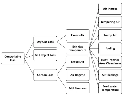
THE VARIOUS HEAT LOSSES AND THEIR THERMODYNAMIC RELATION:
FIGURE 1: Controllable losses in Boiler
Cp = specific heat of flue gas in kCal/kg °C, usually 0.24
FGT= the flue gas temperature, °C
Table 1: Classic Instruments used for Boiler efficiency estimation and its measured parameter Instrument Type Measurements Flue gas
analyzer
Portable or fixed
% CO2 , O2 and CO
Temperature indicator
Thermocouple, liquid in glass
Fuel
temperature, flue gas temperature, combustion air temperature, boiler surface temperature, steam temperature Draft
gauge
Manometer, differential pressure
Amount of draft used or available
TDS meter Conductivity Boiler water TDS, feed water TDS, Make-up water TDS. Flow
meter
As applicable
AAT= the ambient air temperature, °C
GCV= the higher heating value of the fuel, kCal/kg.
H2= weight fraction of hydrogen in the ultimate
analysis of the fuel = kg of hydrogen present in fuel on 1kg basis.
Cp = specific heat of superheated steam in kCal/kg °C
AAT = the ambient air temperature, °C584=latent heat for corresponding partial pressure of water vapour in kCal/kg.
M = kg of moisture present in fuel on 1kg basis.
CO = volume of CO in flue gas leaving economizer in %.
CO2= actual volume of CO2 in flue gas in %.
C= carbon content kg/kg of fuel.
FC= Fuel consumption in kg/hr.
AMA = Actual mass of air supplied per kg of fuel.
HF=Humidity Factor =
TAC=total ash collected per kg of fuel burnt.
1. Heat loss due to dry flue gas:
This is the greatest boiler loss and can be calculated with the following formula
Where,
m = combustion products from fuel: CO2 + SO2 +
nitrogen in fuel + nitrogen in the actual mass of air supplied + O2 in flue gas. (H2O/water
vapours in the flue gas should not considered)
For Quick and simple calculation of boiler efficiency use the following. Simple method can be used for determining the dry flue gas loss as given below
Total mass of flue gas (m)/kg of fuel = mass of actual air supplied/kg of fuel + 1 kg of fuel.
2. Heat loss due to evaporation of water formed due to H2 in fuel (%):
3. Heat loss due to moisture present in fuel (%):
This moisture loss is made up of the sensible heat to bring the moisture to boiling point, the latent heat of evaporation of the moisture, and the superheat required bringing this steam to the temperature of the exhaust gas.
4. Heat loss due to moisture present in air (%):
Vapour in the form of humidity in the incoming air, is superheated as it passes through the boiler. Since this heat passes up the stack, it must be included as a boiler loss.
5. Heat loss due to partial combustion (%):
The generated products by partial include CO, H2,
and various hydrocarbons and are generally found in the flue gas of the boilers. CO is the only gas whose concentration can be determined appropriately in a boiler efficiency testing process.
When CO in ppm,
L₅%= CO in ppm x 10-6
x FC x 28 x 5744 L₅% =%CO%CO+% x CCO₂xGCVof5744 coalx100% L₄% =AMAxHFxCpGCVof₂ x coalFGT − AAT } x100% L₃% = M{584+CpGCVof₂ x FGT − AAT }
coal x100%
L₂% =
[9 x H₂ x {584+Cp₂ x FGT − AAT }]
GCVofcoal x100%
6. Heat loss due to radiation and convection (%):
The actual radiation and convection losses are difficult to assess because of particular emissivity of various surfaces, its inclination, air flow pattern etc. Normally surface loss and other unaccounted losses is assumed based on the type and size of the boiler as given below:
For industrial fire tube / packaged boiler = 1.5 to 2.5%
For industrial water tube boiler = 2 to 3%
For power station boiler = 0.4 to 1%
7. Heat loss due to unburnt in fly ash (%):
Small amounts of carbon will be left in the ash and this constitutes a loss of potential heat in the fuel. To assess these heat losses, samples of ash must be analyzed for carbon content.
8.Heat loss due to unburnt in bottom ash (%):
CONCLUSION
As with any steam generator, the boiler and its auxiliary equipments can be considered a series
of heat exchangers or several components
transferring energy through the system.
Understanding the total energy distribution or “heat distribution” through operating at or above this pressure results in conditions where the water and saturated steam are in single phase and fuel quality will make efficient way to utilise the energy demand for the single source of electrical energy conversion with process changeover parameter.
Efficient way of optimization of energy is relevant to economic heat transfer. Optimization
process of saving the coal energy is linked to heat rate and efficiency improvements.
The leading change in unit size from subcritical units to supercritical units will make the process conversion and which enable the power generation cost or production costs can be largely influenced by fuel flexibility options, heat rate, and condition of plant operating equipment’s. Thus by the way of changing the efficiency along with process parameter will make optimize coal consumption and saving of fuel for plant life operation and its management.
Overall heat transfer of the system and yields uncontrolled “lower furnace” combustion that impacts sustainability and control of emissions at the back-end if control, monitoring and tuning is not proactively employed.
REFERENCE
I. Caneiro, A., Bonnat, M. and Fouletier, J. ,1981 , Measurement and regulation of oxygencontent in selected gases using solid electrolyte cells.
II. Chen, J., Wang, Z. and Sun, Y. , 2002 , Journal of Applied Electrochemistry 1, 83– 90. How to improve control system performance using FF function blocks.
III. Mossin, E.A. and Pantoni, R.P. , 2009, IEEE
International Conference on Control
Application, 1022–26. A fieldbus simulator for training purposes.
IV. ISA Transactions 48, 132–41. Fieldbus
Foundation. 1999a: Foundation specification function block application process. part 1: FF-890-1.3. Austin, TX.
V. Fieldbus Foundation, Austin, TX.,1999b,
Foundation specification function block application process. part 3: FF-892-FS1.4.
VI. Rahul Dev Gupta, SudhirGhai, Ajai Jain.
“Energy Efficiency Improvement Strategies for Industrial Boilers: A Case Study”. Journal of Engineering and Technology. Vol 1. Issue 1. Jan-June 2011.
VII. R. A. Zeitz, Energy Efficiency Handbook, Council of Industrial Boiler Owners (CIBO- Burke VA), pp. 25-65, 2003.
VIII. Virendra, Energy Conservation Potential in Coal Handling Plants of Thermal Power Stations, J Energy Mgmt, pp. 11-22, July-Sept 1997.
L₈% =TACx GCVGCV of bottomash
of coal x100% L₇% =TACGCVx GCV of fly ash
IX. Boiler Efficiency, Source: Cleaver Brooks, web site, 9/01 .www.cleaver-brooks.com.
X. Energy Hand book, Second edition, Von