SELECTED TECHNICAL ASPECTS OF TU-154M SMOLENSK AIR
CRASH ON APRIL 10, 2010
Jacek F. Gieras
Department of Electrical Engineering, University of Technology and Life Sciences, Bydgoszcz, Poland
Abstract.This is a collection of reports that consists of three parts. The author is a Professor of Power
Electrical Engineering, so he focuses on the Tu-154M power electric system and all aspects of the air crash that relate to electrical equipment and wiring.
Part I discusses the electric power system of the Tu-154M. After brief introduction to aircraft electric power systems, the results of reverse design and analysis of GT40PCh6 wound-field synchronous generator including short circuit have been presented. An example of failure of GT40PCh6 generator is the fire of the Tu-154B-2 on January 1, 2011 before taking off at Surgut airport (flight 7K348). Guidelines for proper investigation of aircraft electric equipment and wiring after crash have been given. There is no evidence of examination of most electrical equipment of the Tu-154M No 101 after crash on April 10, 2010. It is now extremely difficult to determine, if the electric power system of the Tu-154M No 101 was operating correctly in the last seconds of the flight, or not.
Part II analyzes the fuel system and possibility of explosion of fuel-air mixture as a result of static electricity and/or arcing in the left wing outer fuel tank of the Tu-154M No 101. Examples of explosions of fuel tanks (Boeing 747-131 TWA 800 on June 17, 1996 and Boeing 727-200 at Bangalore Airport on May 4 2006) have been discussed. Although probability of explosion of fuel-air mixture in the left wing outer tank due to static electricity, electric short circuit or arcing is low, this problem should be carefully considered in future examination of the wreckage and remaining electrical wiring and equipment.
Part III describes a comparative analysis of full-scale dynamic crash test of Douglas DC-7, full-scale dynamic crash test of Lockheed Constellation 1649 and hypothetical collision of the Tu-154M No 101 with birch tree, The analysis pertains to the technical data of the DC-7, LC-1649 and Tu-154M airliners, differences in their construction and conditions of collision/impact.
Keywords: Aircraft, collision, comparative analysis, crash, DC-7, electric equipment, electric power system, explosion, failure, fuel-air mixture, fuel tank, full-scale test, investigation after crash, LC-1649, synchronous generator, Tu-154M, wing, wiring.
Background
On April 10, 2010, a Polish Air Force Tupolev Tu-154M, registration number 101 carrying Poland’s Pres-ident Professor Lech Kaczynski, the First Lady Mrs Maria Kaczynska, top Polish Army generals, Polish representatives, and many distinguished Polish persons performing a states flight from Warsaw (Poland) to Smolensk (Russia) crashed onto the ground coming to rest about 500 m short of the runway threshold of Smolensk North (Severniy) Military Air Base (XUBS). All 88 passengers and 8 crew members have been killed. The debris field being about 210 meters long shows un-believable fragmentation of the aircraft since the speed
of the aircraft was only 260 to 270 km/h and the aircraft hit the boggy and woody ground. The crash investiga-tion has been handed over by Polish authorities to Rus-sia’s Interstate Aviation Committee (Miezhgosudarstvi-enniy Aviatzionniy Komitiet – MAK). The wreckage and flight recorders (black boxes) have not been returned to Poland and are still kept in Russia.
Part I discusses electric power system of the Tu-154M. After brief introduction to aircraft electric power systems, the results of reverse design and analysis of GT40PCh6 wound-field synchronous generator includ-ing short circuit has been presented. An example of fail-ure of GT40PCh6 generator is the fire of the Tu-154B-2
on January 1, 2011 before taking off at Surgut airport (flight 7K348). Guidelines for proper investigation of aircraft electric equipment and wiring after crash have been given. There is no evidence of examination of most electrical equipment of the Tu-154M No 101 after crash on April 10, 2010. It is now extremely difficult to de-termine, if the electric power system of the Tu-154M No 101 was operating correctly in the last seconds of the flight, or not.
Part II analyzes the fuel system and possibility of ex-plosion of fuel-air mixture as a result of static electricity and/or arcing in the left wing outer fuel tank of the Tu-154M No 101. Examples of explosions of fuel tanks (Boeing 747-131 TWA 800 on June 17, 1996 and Boeing 727-200 at Bangalore Airport on May 4 2006) have been discussed. Although probability of explosion of fuel-air mixture in the left wing outer tank due the static elec-tricity, electric short circuit or arcing is low, this problem should be carefully considered in future detailed exam-ination of the wreckage and remaining electrical wiring and equipment.
Part III discusses a comparative analysis of full-scale dynamic crash test of Douglas DC-7, full-scale dynamic crash test of Lockheed Constellation 1649 and hypothet-ical collision of the Tu-154M No 101 with birch tree. The analysis pertains to the technical data of the DC-7, LC-1649 and Tu-154M airliners, differences in their construction and conditions of collision/impact.
Part 1:
Evaluation, Investigation
Techniques and Possibility
of Malfunction of
Electric System of
Tu-154M
1.1
Introduction to aircraft electric
power systems
The function of the aircraft electrical system is to gen-erate, regulate and distribute electrical power through-out the aircraft [23, 35]. Aircraft electrical systems and components operate on many different voltages both AC
and DC. Most systems use three-phase, 115/200 V AC, 400 Hz and 28 V DC. There are several different electric generators on large aircraft to be able to handle loads, for redundancy, and for emergency situations, which in-clude (Fig. 1.1) [23, 35]:
• engine driven main generators;
• auxiliary power units (APU);
• ram air turbines (RAT);
• external power, i.e., ground power units (GPU). Each of the engines on an aircraft drives one or more a.c. generators (Fig. 1.2) via special transmission sys-tem.
Figure 1.1: Aircraft generators: 1 – main generator, 2 – APU, 3 – RAT, 4 – GPU [23, 35].
The power produced by these generators is used in normal flight to supply the entire aircraft with electric power. The power generated by the APU is used while the aircraft is on the ground during maintenance and for engine starting. Most aircraft can use the APU while in flight as a backup power source. RATs are used in the case of a generator or APU failure, as an emergency power source. External power (GPU) may only be used with the aircraft on the ground. A GPU (portable or stationary unit) provides AC power through an exter-nal plug on the nose of the aircraft. Aircraft generators are typically three-phase, salient pole, wound-field rotor synchronous machines with synchronous brushless ex-citer and permanent magnet (PM) brushless subexex-citer [23, 35]. The architecture and power circuit is shown in Fig. 1.2. Engine driven PM brushless generators are rather avoided due to difficulties with shutting down the power in failure modes. A generator control unit (GCU), or voltage regulator, is used to control generator output. The generator shaft is driven by a turbine engine with the aid of gears or directly by low spool engine shaft.
Figure 1.2: Architecture of a three-machine synchronous generator set. 1 – three-phase stator (armature) of main generator, 2 – salient-pole rotor with field excitation winding of main generator, 3 – shaft, 4 – toothed wheel of step-down gear, 5 – end bell, 6 – housing, 7 – rotating diode rectifier, 8 – three-phase rotor (armature) of ex-citer, 9 – stationary field excitation system of exex-citer, 10 – three-phase stator (armature) of subexciter, 11 – PM rotor of subexciter, 11 – bearing, 12 – GCU [23, 35].
a device for converting a variable speed to constant speed is necessary [35]. The so called constant speed drive
(CSD), i.e., a complex hydromechanical device was com-mon until the late 1980s [35]. Nowadays, solid state converters have replaced unreliable CSDs withvariable speed/constant frequency(VSCF) systems.
1.2
Tu-154M power system
The main power supply system of the Tu154M is a three-phase 115/200V, 3×40 kVA, 400 Hz, AC sys-tem [19, 49]. The three-phase 115/200 V AC power is delivered by three GT40PCh6 wound-field synchronous generators. The fourth GT40PCh6 AC generator is the APU generator. The APU is also equipped with 27 V DC GS-12TO starter-generator.
The secondary three-phase, 36 V, 400 Hz, 46.8-A, 2×3 kW AC system takes power from the main system via two three-phase 206/37 V, Dy, TS330S04B transform-ers. The primary windings of TS330S04B transformers are fed from the navigation piloting system (NPK) bus bars. The 115/200 V AC and 36 V AC power system are shown in Fig. 1.3 and described in Table 1.1. The third power system is the 27 V, 200 A, DC, single-circuit system (Fig. 1.4), which receives power from the main system via transformer and three VU-6A rectifiers and four 20NKVN-25 batteries.
The emergency 36 V AC power system (instead of RAT) consists of 20-30/36 V, 400 Hz, 250 VA two PTS-250 transistor inverters fed from batteries. It feeds among others the gyro horizon AGR-144. An-other single-phase 115-V emergency system takes elec-tric power from batteries via POS-125TCh solid state
Figure 1.3: Main power distribution systems 115/220 V AC and 36 V AC of Tu-154M. 1 - rectifiers VU-6A (backup and No 1), 2 - rectifier VU-6A No 2, 3 - right junction box (JB) 115/200 V, 4 - converter PTS-250 No 2, 5 – converter PTS-250 No 1, 6 – JB of kitchen, 7 – JB of anti-ice system, 8 – right panel of generators, 9 – generator GT40PCh6 No 3, 10 – JB of APU 200 V, 11 – generator GT40PCh6 of APU, 12 – generator GT40PCh6 No 2, 13 – generator GT40PCh6 No 1, 14 – external power connector for ShRAP-400-3F GPU, 15 – left panel of generators, 16 – left JB 115/220 V, 17 – transformer No 2, 18 – transformer No 1, 19 – right JB 36 V AC, 20 – left JB 36 V AC, 22 - flight attendant switchboard, 23 – converter POS-125TCh [49].
converter. The simplified electrical diagram of the 115/200 V AC electric system is shown in Fig. 1.5. The block diagram of overall electric system of the Tu-154M is shown in Fig. 1.6.
1.3
Electric power distribution
The main three-phase, 115/200 V, 400 Hz power sup-ply system is a three-channel system (Figs 1.3 and 1.5). One GT40PCh6 generator feeds one channel (electric grid).
The generator No 1 mounted on the left turbofan en-gine No 1 feeds the grid No 1, which in turn feeds the left autonomous bus bars, left bus bar of navigation pilot-ing system (NPK), radio navigation equipment, anticol-lision flashing lights SMI-2KM, control systems of slats and stabilizers (motors No 1), fuel pumps No 1,3,5,8,10, rectifiers VU-6B No 1 (No 3), passenger cabins light-ing, heaters of windshields of cockpit, hydraulic pump-ing station NS-46 of the second hydraulic system, and other loads. The total power consumption of the grid No 1 is 23.2 kVA, 70 A (excluding NS-46).
The generator No 2 of the grid No 2 mounted on the center engine No 2 feeds anti-ice electric heating ele-ments of leading edges of wings (slats). The power con-sumption is 43.6 kVA, 130 A.
sta-Figure 1.4: Power distribution system 27 V DC of Tu-154M. 1 – Rectifier VU-6A No 2, 2 – right panel of pro-tection control, 3 – Rectifier VU-6A No 1, 4 – Left panel of protection control, 5 – junction box (JB) of kitchen, 6 - left power JB 27 V DC, 7 – electrical panel of flight attendant, 8 – rear JB (in left panel of generators), 9 – JB of APU and batteries, 10 – batteries 20NKBN-25, 12 – JB of batteries, 12 – JB of backup VU-6A rectifier, 14 – backup rectifier VU-6A, 15 – “PT” JB, 16 – electrical panel of household devices, 17 – electrical panel of crew dashboard, 18 – flight attendant switchboard [49].
bilizers (motors No 2), fuel pumps No 2,4,6,7,9,11, fuel control system, rectifiers VU-6B No 2 (No 3), air condi-tioning system, hydraulic pumping station NS-46 of the third hydraulic system, household equipment and other equipment. The total power consumption is 12 kVA, 45 A (without household equipment and NS-46). The household equipment needs 13 kVA, 60 A.
In the case of failure of one of the generators, its grid is automatically reconnected to the operating generators.
The GPU supplies all three electric grids. After start-ing any turbofan engine and after switchstart-ing on any GT40PCh6 generator, the first and the third grid is au-tomatically connected to this generator while the GPU feeds only the second grid. If two generators are on, the GPU is automatically disconnected from the aircraft electric power system.
Control and protection devices of the main power sys-tem are located on the power panel of the flight engi-neer. The three-phase 36-V, 400-Hz, two-channel elec-tric power system feeds the Kurs-MP-2 landing naviga-tion and control unit, ARK-15M radio compass, Groza-154 radar, Doppler effect velocity and drift angle mea-sure system DISS-3P, hydraulic presmea-sure gauge MET-4B. The 36 V AC system also supplies the gyro horizon (attitude indicator), but its power is supplied indepen-dently of the PTS-250 converter, which receives electri-cal energy from batteries. The PTS-250 No 1 converter is used as an emergency 36 V AC power source (Fig. 1.6).
Figure 1.5: Simplified schematic of main electric power system 115/220 V AC when all generators G1, G2, and G3 are in parallel. 1 – contactor TKS133DOD “recon-nection of grid No 1 on generator No 3”, 2 – contac-tor TKS233DOD “switching generacontac-tor No 1 on grid”, 5 – contactor TKS233DOD “switching APU on grid No 2”, 17 – contactor TKS233DOD “switching generator No 2 on grid”, 20 – contactor TKS233DOD “reconnec-tion of grid No 3 on generator No 1”, 21 – contactor TKS233DOD “switching generator No 3 on grid”, 27 – contactor TKS233DOD “switching APU or GPU on grid No 3”, 38 – contactor TKS233DOD “switching APU on grid” [30].
Connection of the converter to the network is made au-tomatically.
The on-board 27 V DC power system consists of three VU-6A rectifiers, GS-12TO starter-generator mounted on the APU, and two four 20NKVN-25 batteries (Fig. 1.4). The VU-6A rectifiers are the basic DC power sources. They get the power from the first and third grid (from the main 115/200 V AC system). There are two basic rectifiers and the third rectifier is for redundancy (Fig. 1.6). The third rectifier is switched on automati-cally in the case of failure of one of the basic rectifiers and operates in parallel with the remaining rectifiers. There is also provision for ”forced” connection of the third reserve rectifier.
Figure 1.6: Block diagram of electric power system of Tu-154M [54].
installed in the rear fuselage under the floor of the tech-nical compartment. They can be accessed through a removable hatch in the floor.
In addition, there is a 27 V AC power supply designed for household appliances: electric kettles and electric warmer in the kitchenette-buffet. The system gets its power from the main system through a TS-330S04A transformer connected to the grid No 3 via a switch mounted on the flight attendant switchboard (Figs 1.3 and 1.4). The transformer is installed on the right board, near the frame No 35, in junction box (JB) of the kitch-enette (Fig. 1.3).
The single-phase 115 V AC, 400 Hz power supply pro-vides electric power to Landish-20 FM radio station, ra-dio system RSBN-2SA of near-range navigation, Kurs-MP-2 navigation and control unit, and other radio equip-ment, as well 2IA-7A temperature meters of engine ex-haust gases. In the case of emergency, the electrical power to these loads comes from the converter MA-100M, which is supplied from batteries. The connection of inverter is made automatically.
The lighting equipment of the Tu-154M consists of external and internal equipment. External equipment is intended for taxiing, takeoff, landing, and indicate the plane in the air space at night. Interior equipment is used for illumination of cockpit, passenger cabin and other compartments of aircraft, and emergency lighting. The external lighting equipment includes wing navi-gation (position) lights BANO-57 with 70-W SM-28-70 lamps, 115-V, 45 flare/min SMI-2KM anticollision flash-ing lights, and 27-V, 35.5 A PRF-4 landflash-ing/taxi lights.
The cross section of basic distribution wires is:
Figure 1.7: Turbofan engine D-30KU. 1 – inlet guide vanes heating collector (VNA), 2 – centrifugal air separa-tor of oil system, 3 – fuel-oil heat exchanger, 4 – main oil pump, 5 – front (main) accessory drive gearbox, 6 – hy-draulic pump for thrust reverse, 7 – fuel pump, 8 – sen-sor of referred revolutions, 9 - place for aircraft hydraulic pumps NP-25 and NP-89, 10 – fuel pump regulator, 11 – temperature sensor, 12 – centrifugal regulator of low pressure (LP) rotor, 13 – rotational speed sensor for the LP rotor, 14 – synchronous generator GT40PCh6, 15 – rear accessory drive gearbox, 16 – constant speed drive (CSD), 17 – mechanism of frequency correction, 18 – air turbine of CSD, 19 – air turbo starter, 20 – overlapping cover of turbo starter, 21 – oil removal pump.
http://commons.wikimedia.org/wiki/File:D-30KU-jet-engine.jpg
• 1.93 to 35.0 mm2 for AC systems
• 1.5 to 70.0 mm2for DC systems
1.4
Abnormal operation of electric
power system
1.4.1 Failure of one generator or engine When one generator GT40PCh6 or engine does not operate and the anti-ice electric system of slats is on, the following loads can be switched on
• in flight – one hydraulic pumping station NS-46 without any restrictions;
• at landing – one hydraulic pumping station NS-46 provided that grids No 1 and 3 are loaded below 110 A.
Figure 1.8: APU with GT40PCh6 synchronous gener-ator and TA-6A turboshaft engine. 1 – fuel pump-regulator, 2 – sensor of tacho generator, 3 – synchronous generator GT40PCh6, 4 – leads of synchronous genera-tor, 5 – air-oil heat exchanger, 6 – adapter, 7 – fan, 8 – stabilizer of oil pressure, 9 – front suspension rigging, 10 – grid of compressor, 11 – radial-circular entrance, 12 – compressor, 13 – gas collector, 14 – combustion cham-ber, 15 – evaporation tube, 16 – head of flame tube, 17 – snail, 18 – exhaust pipe, 19 – air bypass pipeline, 20 – turbine, 21 – air regulator, 22 – bleed air pipe, 23 – spring, 24 – reducer [19].
1.4.2 Failure of two generators or enginesIn the case of failure of any two generators GT40PCh6 or tur-bofan engines, the sequence of switching on the NS-46 hydraulic pumping stations is the same as in the case of failure of only one generator (engine) when the anti-ice electric system of slats is connected, but it can be fed only from the APU GT40PCh6 generator.
1.4.3 Failure of all three generators or engines
If all three GT40PCh6 generators must be shut down (fire or fume coming out of electrical equipment), it is allowed on aircraft with autonomous bus when hydraulic pumping station must operate to switch on one of the generators provided that the emergency switch of the active generator is disabled.
When all three generators do not work, the electric power is supplied from the following sources [19, 54]:
(a) Batteries
• emergency converters 115 V AC and 36 V AC;
• engine starting system in the air;
• fire extinguishing system;
• valves that connects hydraulic systems to steering drives (boost control), valve charging the hydraulic accumulator of emergency braking;
Figure 1.9: Wound-field air-cooled synchronous gener-ator GT40PCh6: 1 – armature core of main genera-tor, 2 – armature winding of main generagenera-tor, 3 – ar-mature winding of exciter, 4 – arar-mature core of exciter, 5 – field winding of exciter, 6 – pole, 7 – field excita-tion system of exciter, 8 – rotor pole of main genera-tor, 9 – armature of subexciter, 10 – PM, 11 – arma-ture winding of subexciter, 12 – end shield, 13 – noz-zle, 14 – housing, 15 – bearing, 16 – hollow shaft of rotor, 17 – shaft end, 18 – flanges, 19 – fan, 20 – field winding of main generator, 21 – point of lubrication. http://s010.radikal.ru/i314/1010/42/cba147b70185.jpg
• management of inner and middle spoilers and lights indicating their position;
• manual control of flaps;
• control of main and front landing gears;
• control and trim of enroute load feel mechanism (rudder and elevator);
• correction switches VK-90 No 1 and 4 of gyro hori-zon;
• valves of bleed air in the case of NK-8-2U turbofan engines1, pressurization valves, pressure relief from pressurized cabin, backup system of pressure con-trol, gauges of air temperature in passenger cabin and pipelines;
• valves of switching aniti-ice system of turbofan en-gines and air intakes of wings and tail;
• anti-ice system of gauges of full pressure (PPD);
1only on Tu-154, Tu-154A, Tu-154B, Tu-154B1 and Tu-154B2
Figure 1.10: Magnetic flux distribution in the cross sec-tion of GT40PCh6 synchronous generator as obtained from the 2D FEM. Author’s simulation at the Univer-sity of Technology and Life Sciences, Bydgoszcz, Poland.
• radio compass ARK-15M;
• accurate direction (heading) system TKS-P2 (chan-nel No 1);
• aircraft intercom SPU-7, SGU-15, on-board voice recorder MARS-BM;
• Baklan No 1 and 2 radio stations;
• flight data catastrophic recorder MSRP-64;
• indicators of oil level, tachogenerators of engines, outside temperature indicators;
• light and sound signaling;
• headlights and aicraft navigation lights (ANO);
• illumination of cockpit;
• APU fuel pumps ECN-319 (27 V DC);
• “exit” sign lights, emergency lights of passenger cabin, restrooms and lobbies;
• display of flight azimuth and turning the aircraft around its vertical axis;
• relief valves of the air of pressurized cabin.
(b) Emergency 115 V AC POS-125Ch solid state converter
The emergency 115 V AC POS-125Ch converter feeds only only indicators of gas temperature behind the tur-bines of engines.
(b) Emergency 36 V AC PTS-250 No 1 transistor inverter
Table 1.1: AC power systems of Tu-154 Voltage, V 115/220 36 Number of phases 3 3 Nominal power of the system 120 kVA 6.0 kW Number of channels 3 2 Nominal power per channel
(one generator)
40 kVA 3.0 kW Maximum power per channel 50 kVA 3.75 kW 5-min overload power 60 kVA 4.50 kW 5-s overload power 80 kVA 6.0 kW Frequency, Hz 400 400 Nominal current per channel,
A
111 46.8 Maximum current per channel 138 58.0 Power factor 0.8 to 1.0 0.8
• backup gyro horizon (attitude indicator) with VK-90 correction switch;
• radio compass ARK-15M;
• pressure gauges of hydraulic system;
• indicator of direction angles IKU-1A installed on the dashboard of the aircraft commander and nav-igator;
• compact vertical gyro MGV No 1 (to determine the spatial position of the aircraft in roll and pitch).
(b) Emergency 36 V AC PTS-250 No 2 transistor inverter
• accurate direction (heading) system TKS-P2 (chan-nel No 2);
• flight data catastrophic recorder MSRP-64;
• first subchannel of trimming enroute load feel mech-anism (rudder and elevator).
1.5
Synchronous generators
The main generators are three CSD 40-kVA, 115/200 V, 400 Hz GT40PCh6 wound-field synchronous genera-tors driven by three D-30KU turbofan engines (Fig. 1.7). Each generator feeds one channel. The reserve 40-kVA, 115/200 V, 400 Hz power source, the so called APU consists of GT40PCh6 synchronous generator driven by independent TA-6A turbine engine (Fig. 1.8). The Tu-154M is not equipped with the RAT emergency wind turbine.
Table 1.2: Parameters of GT40PCh6 synchronous gen-erator
Stator
Number of phases 3 Rated speed, rpm 6000 Rated frequency, Hz 400 Stator phase voltage, V 115 Stator rated current, A 111 Armature winding resistance per phase at 25◦C, Ω
0.0264 Base impedance, Ω 0.9919
d-axis synchronous reactance, p.u. 1.954
q-axis synchronous reactance, p.u. 0.776
Rotor
Type of rotor salient pole Pole arc-to-pole pitch ratio 0.58 Number of poles 8 DC field current at nominal load and PF=0.75, A
45.58 Total moment of inertia, kgm2 approx. 0.06
packaging point of view, the PM brushless subexciter is placed inside the exciter.
The GT40PCh6 generator operates smoothly under the following conditions:
• ambient temperature from +100 to−60◦C;
• cooling air temperature from +60 to−60◦C;
• atmospheric pressure up to 124 mm Hg;
• effects of frost and dew;
• shock accelerations up to 6g.
The housing monoblock is made of magnesium al-loy with pressed steel sleeve mounted on the drive side around the ball bearing. The bearing nest has a pocket for the collection of waste grease that is removed from it with the aid of a plunger. Lubricant is applied to the bearing on the oil line through the point of lubrication. There are longitudinal ribs on the inner surface of the housing, which increase its rigidity and form channels for passage of cooling air. Windows in the enclosure at the drive side are designed to exit the air. A titanium flange screwed to the end shield mounts the generator on the engine. A box on the outer surface of the housing contains a differential current transformer for protection of the generator.
The rotor has two ball bearings. Seals of the bearings are of threaded type with extra cuffs. The rotor salient
Figure 1.11: Armature current Iash at two
lines-to-neutral short circuit of GT40PCh6 synchronous genera-tor. The peak short-circuit current isIashp =−1130 A
corresponds tot= 0.6 ms [20].
poles, armature of the exciter and PMs of subexciter are pressed on the hollow shaft. The rotating rectifier consists of six D232A silicon diodes.
Cooling of the generator is accomplished by blowing air at a flow rate varying from 0.1 to 0.3 kg/s [19].
Dimensions, material data and winding diagrams of the GT40PCh6 synchronous generator are not avail-able [19, 44, 49, 54]. To obtain dimensions, winding parameters and detailed performance characteristics of GT40PCh6 synchronous generators (Table 1.2), a re-verse design on the basis of available sources [19, 44, 49, 54] has been done. The 2D FEM has been used for electromagnetic synthesis and analysis [20]. The 2D magnetic flux distribution in the cross section of the GT40PCh6 main generator is shown in Fig. 1.10. The obtained short-circuit current waveforms, e.g., Fig. 1.11 are very important since the subtransient and transient short-circuit currents help to evaluate the possible dam-age during the electrical power system failure.
Short-circuit currents can exceed more than 11 times the nominal current. The most dangerous is two lines-to-neutral short circuit (Fig. 1.11).
1.6
Failures of synchronous
genera-tors
The mean time between failures (MTBF) of GT40PCh6 synchronous generators is estimated as ap-proximately 8500 to 9000 flight hours [19, 30, 49, 54].
Figure 1.12: Tail part of Tu-154B2 RA-85588 after fire at Surgut airport on January 1, 2011 [30].
Figure 1.13: Closed electric circuit on assumption of abnormal scenario corresponding to the 21st contactor TKS233DOD “switching generator No 3 on grid” [30].
on the Ob River near its junction with Irtysh River) to Moscow (Domodedovo). The plane was taxiing to the runway while preparing for its takeoff from Surgut when the right engine caught fire on the taxiway (Fig. 1.12). Three out of 126 passengers and 8 crew members died.
Russia’s Interstate Aviation Committee (MAK) re-leased their final report (in Russian) concluding the probable cause of the accident was the outbreak of fire in the right generator panel located between frames 62 and 64 in the cabin [30]. The generators were connected on the network after the engine start and exit to the idle mode. The cause of the fire was an electrical arc-ing produced by electrical currents exceedarc-ing 10 to 12 times the nominal current when two generators not syn-chronized with each other were brought online but got
Figure 1.14: Emergency landing of the Tu-154M RA-85684 at abandoned air strip near town of Izhma on September 7, 2010. The impact was damped by the young trees which have grown since the airport was closed. The photograph shows the right wing that cut a pine tree [46].
connected together instead of being connected to parallel busses (Fig. 1.13). Under such conditions the currents can reach more than 10 times the nominal current of the generator. The unsynchronized operation of the gener-ators can be attributed to:
1. Poor technical conditions of contacts TKS233DOD (Fig. 1.13) responsible for connecting the genera-tors with the electrical busses, that were damaged by prolonged operation without maintenance. A contact normally open was welded and fractured in-sulation material moved between contacts that are normally closed. These abnormal contact positions led to the connection between No 2 and No 3 gen-erators (Fig. 1.13).
2. Differences in the schematic diagrams of genera-tor No 2 and generagenera-tors No 1 and 3. When the switch is moved from ”check” to ”enable” with no delay in the ”neutral” position, the generator 2 is brought on line without time delay. This leads to increased wear of normally closed contacts in the TKS233DOD unit. The specific design of the elec-trical systems ensures power supply to each bus from either the APU or engine integrated drive gen-erator.
Figure 1.15: Parameters of flight of the Tu-154M No 101 for electrical equipment and engines on April 10, 2010, 7:14 – 8:41 am. LPC = low pressure compressor. Description in Table 1.4 [14, 15].
Figure 1.16: Electric wires scattered throughout the Tu-154M No 101 wreckage: (a) at the crash site (beside spare landing gear wheel); (b) hanging from heavy trans-portation vehicle.
1.7
Failures
of
other
electrical
equipment
On September 7, 2010, the Tu-154M RA-85684 Alrosa Mirny Air Enterprise Flight 514 aircraft from Udachny (located 1370 km northwest of Yakutsk on the Markha River) to Moscow suffered a complete electrical failure
en route, leading to a loss of navigational systems. The electrically operated fuel transfer pumps were also af-fected and prevented transfer of fuel from the wing tanks to the engine supply tank in the fuselage.
After emergency decent below cloud level the crew were able to spot an abandoned air strip near town of Izhma (Fig. 1.14). The abandoned air strip is 1325m, whereas the Tu-154 requires a minimum of 2200 m. The aircraft landed at a speed of 350 to 380 km/h, faster than normal, due to the lack of flaps. Although the flaps are powered by hydraulics, the switches operating them are electrical. All 9 crew members and 72 passengers evac-uated using the aircraft’s evacuation slides. No injuries were reported.
Figure 1.17: Junction and control boxes of electrical in-stallation. Photo taken at the site of wreckage storage [16].
Figure 1.18: Generator GT40PCh6 on No 1 (left) D-30KU turbofan engine. Photo taken between 11 and 13 April 2010 on the crash site [15].
On November 17, 1990, the cargo TU 154M, SSSR-85664 of Aeroflot Airways was heading through Czech territory with a load of Winston cigarettes from Basel (Switzerland) to Moscow. A switched-on cooker in the kitchenette caused a fire on board of the plane and the crew decided to land at the closest possible place. The crew made an attempt of emergency landing on the field near Dubenec village in the East Bohemia. There were only 6 crew members on board, all of them survived the air disaster.
Table 1.3: Examination of electrical equipment at crash site
Electric equip-ment
Standard procedure [18, 53] Evidence of examination by IAC
(MAK) [29] and/or CINAC
(KBWL) [13]
Electrical wiring Visual inspection of conductors and insulation. Probably Circuit breakers,
switches and relays
Inspection if contacts are free of metal flow and excessive cratering caused by arcing
No evidence Electric generators
and motors
1) Visual inspection
2) Measurements: winding resistance and induc-tance, insulation resistance
3) Machine taken apart: are there any scores and scratches on the inner surface of the stator core, is the shaft bent, what is the condition of bearings?
1) Probably 2) No evidence 3) No evidence
Feeders and buses Testing for tightness, evidence of arcing and erosion of terminal studs, evidence of foreign objects.
No evidence
Light bulbs Examination of glass envelope, filament and evi-dence of powder inside the glass envelope.
Some incandescent light bulbs, e.g., illumination bulbs (filaments) of PU APK-15M automatic radio compass were examined by Russian IAC (MAK) [29]
Figure 1.19: Electromagnetic brake TEM-4 for flap con-trol found several meters behind the famous birch tree. Source: http://www.waronline.org
1.8
Investigation of electrical
equip-ment and wiring after crash
Electrical events happen at the speed of light. Air-craft crash at much lower speed and a lot can happen to electrical system between the first collision with ground or terrain obstacle and complete stop [53]. The state of electrical circuit can change in this very short time inter-val: circuits, which were “on” at initial impact are “off”
Figure 1.20: Location of electromagnetic brake TEM-4 for flap control. 1,3 – bracket, 2,4 – transmission shaft, 5 – reducer, 6 – electromagnetic brake TEM-4, 7 – cardan joint, 8 – lift for the outer flap, 9 – mechanism of limit switches with sensor, 10 – rail of external deflector, 11 – carriage of external deflector, 12 – rail of deflector, 13 – intermediate carriage of deflector [48].
when the wreckage finally comes to stop. Finding the evidence of short circuit or electric arc does not mean that the electrical malfunction has occurred before the accident. It could rather happened during impact.
Before inspection of the wreckage it is recommended to do a homework [18, 53]: i.e.,
• interviewing witnesses (crew members, passenger, outsiders),
Table 1.4: Parameters of electrical equipment plotted in Fig. 1.15.
No Polish acronym Description
1 TABLEAZS27V 27 V is on the left board AZS (automate of grid security) 2 STARTWSU Engine starter is switched-on
3 SZYNAWA36 36 V is on the right bus of PTS-250 No 1 DC to AC converter
4 NPKP1SIEC3 NPK (navigation piloting system) bus is switched from the right grid No 3 to the left grid No 1
5 G1NIESPR Generator No 1 is disconnected from the grid 6 G2NIESPR Generator No 2 is disconnected from the grid 7 G3NIESPR Generator No 3 is disconnected from the grid 8 SIECPR36V 36 V is on the right bus
9 NPKL1SIEC3 NPK bus is switched from the left grid No 1 to the right grid No 3
10 LSIEC36V Emergency voltage 36 V is on the left bus of PTS-250 No 2 DC to AC converter
Evidence in the recordings or statements that some electrical parts and systems were operating correctly prior to impact is more credible that examination of the wreckage and saves investigators a lot of work [18, 53]. If witnesses and recordings are not available, the rec-ommended approach to investigation of wreckage is to prove that theelectrical power was available on the front end and that electrical devices were operating on the rear end of the aircraft (Table 1.3).
1.8.1 Electrical wiring Typical aircraft have from 16 to 160 km of wire installed such that wire from one system is often collocated with wire from many other systems. Electrical wiring can be classified into power wiring (heavy current) and light current wiring. In mod-ern aircraft, power wires, feeding e.g., electric motors, are not routed through the cockpit. Switches in the cock-pit are connected to light current wires (control wires), which active relies of heavy current circuit.
After crash, wiring is normally scattered throughout the wreckage, but major wire bundles remain more or less intact (Fig. 1.16).
Wiring is inspected visually. The condition of wires and their insulation is a good indicator of the source of overheating. External overheating discolor or burn the insulation, while the wire strands should be intact and shiny. Internal or severe external overheating discolor the wire strands.
Older aircraft design allows circuits from multiple sys-tems to be co-bundled along shared raceways in the fuse-lage. This is cost-effective solution, but deterioration of insulation, overheating or arcing of one circuit can also damage to neighboring wires. For example, short cir-cuit in a wire bundle was a root cause of ignition of the flammable fuel/air mixture in the center wing fuel tank (CWT) of Boeing 747-131 (flight TWA 800) on July 17, 1996.
1.8.2 Circuit breakers Circuit breakers protect the wiring, not equipment. Most circuit breakers are ther-mally activated. Arcing in the line does not always open the circuit breaker. However, circuit breakers may open under impact forces.
1.8.3 Electric generators Generators stator wind-ing resistances and inductances should be measured for possible open or short circuits. Also, the resistance be-tween winding terminals and housing should be mea-sured for possible damage to insulation. After external examination and basic electrical measurements, the gen-erator should be taken apart to check for any evidence of scratching on the inside surface of the stator core, bearing failure, bent shaft and insulation overheating. Scoring and scratching on the stator core indicate if the generator was spinning or not before the crash.
1.8.4 Generator feeders Terminals of buses should be tested for tightness, evidence of arcing and erosion of terminal studs, corrosion and foreign objects being in contact with the terminals [18].
1.8.5 Emergency power supply Emergency power supply includes batteries, APU and RAT (not installed on the Tu-154). If one of the main generators fails, there is usually the possibility to connect the inoperative cir-cuit to an operative one (Section 1.4).
difficult to determine whether it was done before or after the impact.
1.8.7 Light bulbs analysis Analysis of light bulbs in the cockpit can tell which lights were on or off at impact. When a tungsten filament burns, it leaves a grayish pow-der, i.e., the tungsten oxide. When the remaining parts of the bulb are coated with grayish powder, the bulb was probably on at the time the glass envelope broke. When the glass envelope was broken and no grayish powder was produced, any evidence of changing the color of filament (from yellow to red to purple to blue) shows that the bulb was probably on. If the color of filament remains unchanged, the bulb was probably off. Broken glass en-velope and intact filament indicates that the bulb was definitely off.
1.9
Examination of electrical
equip-ment of Tu-154M on crash site
Operation of electrical equipment and installation of the Tu-154M is monitored by the MSRP2 flight data
catastrophic recorder with the aid of parameters de-scribed in Table 1.4. Those parameters are plotted in Fig. 1.15 (color lines at the bottom).
The catastrophic recorder MLP-14-5 (part of MSRP) was found on April 10, 2010 by Russians. Data of MLP-14-5 were recorded in the IAC (MAK) headquarters in the presence of Polish military prosecutor on April 11, 2012 [15]. The recording medium (tape) was in good condition [15].
Annexure 4 [15] to the Report [13], Section 7.2 “Anal-ysis of electrical installations” concludes that during the flight on April 10, 2010, the electric system operated correctly, i.e.:
• The main generators GT40PCh6 were connected to the grid immediately after starting the engines in the following sequence: engine No 2 – generator No 2, engine No 1 – generator No 1 and engine No 3 – generator No 3. During the flight, there were no signs of automatic or manual disconnection of any of the generators from the grid, which means that the electric system was operated in accordance with the technical guidelines.
• There were no signs of change of power supply con-figuration of the left and right navigation piloting system NPK buses. NPK buses were fed in accor-dance with the technical guidelines.
• There were no signs of starting the APU.
• There were no signs of the 36-V AC power system malfunction and no signs of automatic or manual
2Magnetic system of registration of parameters.
activation of the emergency power sources for this system.
• There were no signs of the 27-V DC power system malfunction. The voltage on the left bus was within the limits in accordance with technical guidelines and there was no signal of voltage decay on the left bus.
According to latest research of K. Nowaczyk of the University of Maryland [38, 39], the ATM QAR3 has
recorded a damage to the left engine No 1 and syn-chronous generator No 14. Both the 115/200 V and 36
V (LSIEC36) of the left grid dropped to zero before the ground impact (Table 1.4).
There is no evidence that other than visual inspection of electrical equipment and wiring (Table 1.3) has been done on the crash site [13, 15]. The following state-ment is given on p. 20/28 of Annexure 4 [15]: Bun-dles of electrical wires torn apart (Fig. 1.16). Con-trol boxes deformed. Enclosures of on-board batteries deformed. Some cells leaking. The report shows pho-tographs of wire bundles, control boxes (Fig. 1.17), syn-chronous generator GT40PCh6 on the turbofan engine No 1 (Fig. 1.18), batteries and other electrical equip-ment.
The object found at the crash site several meters be-hind the famous “armored” birch three [13] and shown in Fig. 1.19 has been often incorrectly identified as a fuel pump. However, this is the electromagnetic brake TEM-4 used for control of flaps (Fig. 1.20).
1.10
Conclusions
Electric system of the Tu-154M aircraft is an outdated system typical for aircraft being designed in the 1960s. Main synchronous generators are air cooled generators. In comparison with liquid cooling systems, air cooling reduces the rated power and power density, i.e., output power–to–mass ratio of generators. Nowadays, modern VSCF wound-field synchronous generators are oil cooled with rated power up to 250 kVA [35].
Reversed design and analysis of GT40PCh6 main syn-chronous generators deliver important information on the steady-state and transient performance of these ma-chines. Transient characteristics, especially short-circuit waveforms are very helpful in investigation of electric power system after crash.
Credibility of flight parameters for electrical equip-ment and installation (Fig. 1.15) is questionable. There
3On-board recorder of flight parameters manufactured by
Advanced Technology Manufacturing (ATM) Avionics, Warsaw, Poland, http://www.armavio.pl.
4see also
is not enough information how the recorded parameters have been secured, extracted and analyzed [15].
It is now practically impossible to find out if compo-nents of the electric power system was operating cor-rectly in the last seconds of air crash or not. According to [13, 15], the flight management system (FMS) lost electric power (memory freezing) at 10:41:05, i.e., at the time of collision with ground.
Table 1.3 shows standard procedure for examina-tion of electrical equipment and installaexamina-tion after crash [18, 53]. The electrical equipment and wiring at the crash site was only inspected visually [13, 15]. There is still possible to examine synchronous generators and induction motors for fuel pumps and for other on-board equipment. However, the results of examination may not be credible since the wreckage was carelessly loaded on the trailers and then transported, unloaded and stored in open space without any caution.
Part 2:
Hypothesis of
Explosion in the Left
Wing Outer Fuel
Tank of Tu-154M due
to Electrical Ignition
of Fuel-Air Mixture
2.1
Introduction
According to official investigations of the Smolensk air crash [13, 29], the cause of disaster was collision of the Tu-154M No 101 with trees while landing in dense fog. At the distance of 855 m before the threshold of run-way and 63-m left from its center line, the left wing of the aircraft hit a birch tree with the trunk diameter of about 0.4 m at the height of about 6.6 m [9]. As a result, the tip of the left wing of 6.1-m long between the 27th
and 28thrib has been severed. The first ground impact
was 525 m before the threshold of the runway and 105-m left fro105-m its center line. The satellite photograph of the crash site is shown in Fig. 2.1. Distribution, scat-tering and shape of debris, characteristic opening of the
fuselage skin to the outside, dismembered bodies5, torn off clothes as well as lack of crater and fuel fire suggest rather explosion in the air above the ground than ground impact [8, 10, 45].
Figure 2.1: Plane crash site on April 12, 2012. Source: Global Digital.
Figure 2.2: Comparison of the fusalage at the crash site on April 10, 2012 with burst gas cylinder: (a) the fusalage looks like burst from inside, the walls are split along its longitudinal axis and open to the outside (http://krsk.sibnovosti.ru/incidents/103354-
podrobnosti-krusheniya-tu-154-v-smolenskoy-oblasti); (b) burst gas cylinder (http:// www.scubaengineer.com/scuba cylinder videos.htm).
2.2
Problem statement
According to Annexure No 4 [15], Section 4.10.3, the lost of the left portion of the wing has caused the burst of the left fuel tank No 3, which is placed between ribs No 14 and 45. The severance of the 6.1-m long tip of the left wing was between the ribs No 27 and 28.
Since the severance of the wing tip as a result of colli-sion with about 0.4 m diameter live birch tree with many whorls [9] is rather impossible [1, 2], the problem should
5Only 28 bodies out of 96 could be identified without DNA
Figure 2.3: Hypothesis of explosion in the left wing.
be stated in opposite way: The burst of the left fuel tank No 3 caused the lost of the left portion of the wing.
According to [45], the Tu-154M No 101 crash was due to two explosions in the air: one on the left wing (Fig. 2.3) and the second inside the fuselage. An explo-sion is defined as an event leading to increase of pressure due to high explosives, combustion of dust, mist or gas in the air, loss of containment in high pressure vessels, nuclear reaction, etc. [3]. Huge amount of small plane’s pieces and their location on the ground (Fig. 2.1), fuse-lage split along its longitudinal axis (Fig. 2.2), rivets torn out6, lack of crater, etc., exclude the crash caused
by the mechanical impact.
If the explosion on the Tu-154M was due to action of the third party, installation of explosive in the left wing was not necessary. Electric wiring for electricity supply to electric motors of fuel pumps installed in the left wing tank No 3 could be adequately prepared7. It is necessary
to mention that alterations to Salon No 3 were made in Warsaw on April 6, 2010.8
Figure 2.4: Construction of the Tu-154 wing [52].
6A rivet was found in exhumed body of a victim. 7This is a separate problem.
8The number of passenger seats in Salon no 3 was increased
from 8 to 18. Hangar No 21, in which alterations to Salon No 3 of the Tu-154M No 101 were made, has been recently demolished.
Figure 2.5: Left wing on the wreckage storage site: (a) effect of shock wave penetrating inside the wing [45]; (b) severed tip of the wing [16].
Possible reasons for explosion in the left wing include, but are not limited to:
• Ignition of fuel-air mixture due to static electric-ity build-up or arcing in electric wiring or electric equipment;
• Explosive present in the left wing.
The construction of the Tu-154 wing is shown in Fig. 2.4. Its main parts are 3 spars, the upper and lower panels and 45 ribs. Wing ribs are perpendicular to the axis of the third spar. The chambers in their center parts are sealed and used as fuel tanks [44, 50, 52]. The inte-rior of a wing fuel tank of a large aircraft is visualized, e.g., on photographs published on Little Rock Air Force Base web site [6]
The remains of the left wing show the effects of a strong shock wave penetrating inside the wing [45]. There are no spars present between upper and lower skin, which might be an effect of explosion (Fig. 2.5).
2.3
Similar air crashes and full-scale
tests
Similar air crashes are understood as those in which:
• the same aircraft or aircraft of very similar construc-tion crashes;
Figure 2.6: Wrackage of the Boeing 727-232F Fedex flight 1478 at Tallahassee Re-gional Airport (TLH). Source:
http://www.aero-news.net/images/content/commair/2003/fedex727crash0726b.jpg
Figure 2.7: Boeing 727 after crash on Sonoran Desert with its fuselage ripped in two [47]. Compare with Fig. 2.1 .
1478, a Boeing 727-232F, N497FE, struck trees on short final approach and crashed short of runway 9. The air-plane collided with trees in a right-wing-low, slightly nose-up attitude during the approach to runway 9, then impacted the ground, coming to rest on a heading of 260◦about 474 m (1556 feet) west-southwest of the run-way (Fig. 2.6). A postimpact fire ensued; however, the three flight crewmembers exited the airplane through the captain’s side sliding cockpit window before the fire reached the cockpit [12]. The crash site shown in Fig. 2.6 cannot be compared to that shown in Figs 2.1 and 2.2a. The Tu-154M is conceptually similar to the Boeing 727, e.g., both aircraft use a rear engine T-tail configuration, S-duct for the middle (No 2) engine, similar leading edeg sweep of wings, etc.
Recent full-scale experiment9 with a 170-seat
Boe-ing 727 passenger aircraft in a remote and unpopulated
9UK Channel 4 and US Discovery Channel.
Sonoran Desert of Baja California, Mexico, has shown no fragmentation of the aircraft into small pieces un-der ground impact (Fig. 2.7) [47]. The objective was to recreate a serious passenger jet crash landing, so that scientist and engineers could study the impact of air crashes on the human body and aircraft structure. The pilot parachuted out of the cockpit at 762 m before the plane was plunged into the ground via remote-control by a pilot in a following Cessna. As the plane hit the ground with its speed of 225 km/h, the fuselage was torn in two with the nose embedded in the ground. Crash investi-gators predicted that 78% of passengers on board would have survived such ground impact. The TU-154M is a Russian copy of Boeing 727.
Figure 2.8: Wiring configuration on the Boeing 747. In-vestigators suspect that high voltage from the fuel flow meter A passed to the fuel quantity indication system (FQIS) B because of a short circuit in the wire bundle [34].
2.4
Examples of explosions of fuel
tanks
In older (and also many new) types of passenger air-craft the electric wires belonging to different electric cir-cuits are laid in common bundles [18, 53]. It is econom-ical solution, which reduces the cost of electreconom-ical wiring. On the other hand, aging and deterioration of insulation, wire overheating, short circuit or electric arcing in one electric circuit can make damage to insulation and short circuit of wires belonging to other electric circuits. Ther-mal protections are sometimes not reliable. For example, short circuit in a bundle of electric wires caused ignition of fuel-air mixture in the center wing tank (CWT) of the Boeing 747-131, flight TWA 800 on June 17, 1996 (Fig. 2.8). Burst of CWT led to destruction of the air-craft over the Atlantic Ocean [34].
Figure 2.9: Evidence of electrical arcing of the wiring in-side the exploded fuel tank of Boeing 727-200, Transmile Airlines, Bangalore, May 4, 2006 [51].
115-V AC cable feeding fuel pump motor in the left wing tank (Fig. 2.9).
2.5
Tu-154m fuel system
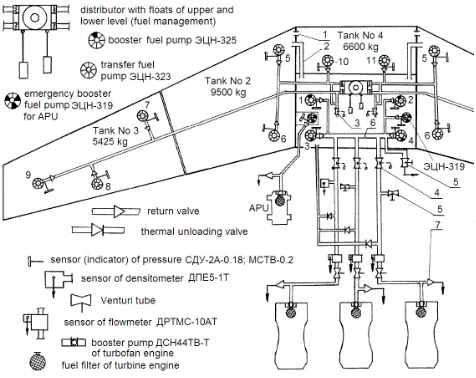
Civil transport aircraft use the wing structure (Fig. 2.4) as an integral fuel tank to store fuel. In larger aircraft, the fuel is also stored in the structural wing box within the fuselage. A typical wing tank is irregu-lar, long and shallow [35]. The fuel is in direct contact with the outside skin. The Tu-154M has six fuel tanks: one central fuel tank (CWT) No 1, two inner wing tanks No 2, two outer wing tanks No 3 and one additional tank No 4. The Tu-154M fuel tank configuration is shown in Figs 2.10 and 2.11. Tanks No 3 are between spars 1 and 3 and ribs 14 and 45 of detachable parts of wings [50].
Figure 2.10: Tu-154M fuel tank configuration: No 1 – center wing tank (CWT), i.e., collector tank, No 2 – inner left and right wing tank, No 3 – outer left and right wing tank, No 4 – additional tank [50].
The CWT tank is generally categorized as hazardous due to the proximity to external heat sources, e.g.,
air-conditiong units [35]. It requirestank inerting with the aid of nitrogen-enriched air from the on-board inert gas generating system. The tanks No 1 and 4 of the Tu-154M are inerted in the case of emergency landing with-out landing gears. The left and right wing tanks are usually categorized as nonhazardous as there is mostly no proximity of heat sources [35]. The wing leading edge slat section is equipped with anti-ice control system, typ-ically with hot air ducts. These ducts take form of pipes with holes to allow air to heat the inner surface of lead-ing edges. The hot air flow to the outer wlead-ing leadlead-ing edges is controlled by the wing anti-ice valve [35]. The Tu-154M haselectric anti-ice control system with heat-ing elements embedded in slats. Malfunction of electric anti-ice control system can theoretically cause dissipa-tion of heat in the vicinity of the wing fuel tank No 3 (Sections 2.6 and 2.7). According to [13], the electric anti-ice system of slats has not been activated during the flight Warsaw–Smolensk on April 10, 2010.
Table 2.1: Fuel pumps of Tu154M. Specifications ECN-319
ECN-323
ECN-325 Type of pump Emergency
booster
Transfer Booster Electric motor DC Induction Induction Voltage, V 27 200 200 Rated current A <15 <2.6 <8.3 Starting current unknown <15.6 49.8 Pressure drop,
kG/cm2
1.6 0.45 1.25 Flow, l/h 1,500 2,000...
7,000
3,500... 12,000 Mass of pump, kg 3.8 4.0 5.8 Number of pumps 2 12 4
Fuel pumps of the Tu-154M are driven by 115/200 V AC induction motors and 27 V DC brush motors (Table 2.1). A flange mounted motor and pump constitute one integral unit (Fig. 2.12a). The feeding cables in fuel tanks are in aluminum tubes (Fig. 2.12b). Arcing in wiring system that delivers electric energy to fuel pump motors can theoretically ignite the fuel-air mixture in the wing tank [44, 32, 35, 37, 42].
In general, there are two types of fuel pumps on typical aircraft [35]:
Figure 2.11: Tu154M fuel system layout. Fuel tanks, fuel pumps, fuel transfer lines, D-30KU engine and APU have been shown. 1,2 – feed lines of upper transfer from tanks No 4 and No 1 to tank No 2; 3 – faucet of reserve transfer; 4 – antifire faucet; 5 – discharge faucet, 6 – connector for maintenance of engines [50, 52, 54].
• Fuelbooster pumps(e.g., ECN-325, ECN-319), also called engine feed pumps, which are used to boost the fuel flow from the aircraft fuel system to the engine.
Commercial aircraft useopen vent system to connect the ullage10 space above the fuel in each tank to the outside air [35]. The Tu-154M is equipped with the vent system.
The Tu-154 uses fuel Jet A-1. Jet A-1 is a kerosene grade of fuel suitable for most aircraft turbine engines. It is produced to a stringent internationally agreed stan-dard.
Fuel samples have not been collected from the crash site for testing by the Committee for Investigation of National Aviation Accidents (KBWL11). KBWL tested
fuel taken from the cistern UJ00204 at Warsaw Airport. Laboratory tests have confirmed that the fuel meets quality requirements (Raport Nr WK-2913-55-143-10). According to [29], fuel samples taken from the wreck-age for tests by Russian Interstate Aviation Committee (MAK) has confirmed good quality of fuel.
According to [13], Section 4.10.3, the Tu-154M was fueled on April 7 (22 568 l) and April 9 (9518 l)12. The airplane was not refueled on April 10, 2010.
10Space between the fuel surface and upper wall of the tank. 11In Polish ,,Komisja Badan Wypadkow Lotniczych Lotnictwa
Cywilnego” (KBWLLC or KBWL).
12After return of D. Tusk from Prague.
Figure 2.12: Booster fuel pump ECN-325: (a) cross sec-tion of fuel pump and inducsec-tion motor; (b) electric wires. 1 – grid, 2 – induction motor, 3 – motor housing, 4 – shaft, 5 – tube, 6,7 – sealing rubber rings, 8 – pump housing, 9 – rotor, 10 – cover, 11 – snail, 12 – impeller, 13 – channel, 27 – conduit metal tube, 28 – tubing, 29 – terminal block, 30 – cover, 31 – electric cable. Construc-tion of transfer fuel pump ECN-323 is similar [44, 50].
Assuming that fuel is equally distributed between the left and right wing tanks No 3, it should be from 650 to 725 kg of fuel in the left wing tank No 3 (Table 2.2) at the time of crash [15], Section 4.10.3. The surface of the bottom of the tank No 3 has been estimated approxi-mately as 57 m2. Assuming the specific mass density of
Jet A-1 fuel as 800 kg/m3, the fuel level in the tank No
3 was from 14 to 16 mm. Such a thin layer of fuel on the bottom of a tank needs minimal heat input to the tank walls to reach the temperature exceeding the flash point and form combustible vapors in the ullage.
Table 2.2: Capacity of fuel tanks before and after crash No of tank Nominal
ca-pacity, kg
Last refu-eling, kg
After crash, kg No 1 CWT
(collector tank)
3,300 3,300 3,150 to 3,300 No 2 (two
tanks)
2 x 9,500 = 19,000
4000 0 No 3 (two
tanks)
2 x 5,425 = 10,850
5,372 1,300 to 1,450 No 4
(addi-tional tank)
6,600 6,000 6,000 Total 39 750 1
8,672
Annexure No 4 [15], Section 4.5, p. 28/28 says that during visual inspection of wreckage, no trace of det-onation of explosive and fuel has been found. Visual inspection cannot detect explosives. Detailed chemical examination and analysis of the wreckage must be done.
2.6
Tu-154m wing anti-ice system and
electric wiring
Most civil aircraft use hot bleed air for anti-ice control of outer wing leading edges [35]. The Tu-154M must use electric resistive heating for anti-ice of the wing leading edge slats, as the turbofan engines are tail mounted and located far away from the wings. This would make the hot air bleed system very heavy and cumbersome.
Figure 2.13: Leading edge wing anti-ice system: 1 – slat, 2 – outer skin/sheathing, 3, 5, 7 – thermal glass insulation, 4 – thermal “knife” (NiCr foil), 6 – heating element (composites), 8 – inner skin/sheathing [44, 52]. The Tu-154M has three-phase, 115-V electrical wing anti-ice heating system (Fig. 2.13) [44, 52]. To save elec-trical energy, heating elements are fed cyclically by ade-quate determination of time period. Under cyclic heat-ing a thin layer of ice accumulates on slats which does not deteriorate aerodynamic properties of the aircraft. When the accumulation reaches a thickness threshold and the temperature of skin increases, the ice is taken out by the air stream.
The generator GT40PCh6 No 2 driven by the mid turbofan engine No 2 feeds only electric grid 2 (Fig. 1.5) dedicated to heating wing slats. The electric apparent power is 43.6 kVA at 115 V (phase) and≤130 A.
Heating elements (composites) of one half of slats are divided into eight sections. The other half of slats has
also eight sections. Sections are fed in the following se-quence: 1st, 2nd, . . . 8th, 1st, 2nd, . . . 8th . . . . Sections are numbered starting from the core part of the wing to the end of the wing. The current is on for 38.5 s and off for 269.5 s for each section.
In the leading part a thermal “knife” is installed along the slats. This part is made of 20-mm wide X20H80 NiCr foil. The thermal “knife” is not fed cyclically – it is steadily under current and is isolated from the outer skin by three layers of glass fiber 3 (Fig. 2.13). Also, the three layers 5 isolate the thermal “knife” from the heating element. On the inner skin/sheathing of heating element of the slat, thermal switches for cyclic operation of sections and thermal “knife” are installed. Thermal switches protect slats and heating elements against over-heating.
2.7
Electric ignition of aircraft fuel
Characteristics of aviation turbine engine fuel Jet A-1 are given in Table 2.3. Jet A-1 is a kerosene grade of fuel suitable for most turbine engine aircraft. This is a complex mixture of hydrocarbons consisting of paraf-fins, cycloparafparaf-fins, aromatic and olefinic hydrocarbons predominantly with the C9 to C16 carbon numbers [27]. Theflash pointof the fuel is the minimum temperature at which sufficient vapor is released by the fuel to form a flammable vapor-air mixture near the surface of the liquid or within the vessel used [27]. For Jet A-1 fuel the flash point is 38◦C (Table 2.3).
Table 2.3: Characteristics of fuel Jet A-1 [25] Density at 15◦C, kg/m3 775 to 840 Flash point,◦C 38
Auto-ignition temperature,◦C 210
Freezing point, ◦C – 47 (– 40 for Jet A) Open air burning temperature,◦C 260 to 315 Maximum burning temperature,◦C 980 Minimum net heat of combustion (specific energy), mJ/kg
42.8 Electric conductivity,×10−12 S/m 1.0 to 20.0 Gravimetric energy content, MJ/kg 43.5 Volumetric energy content, MJ/l 31.1
Flammability limits are experimentally determined upper and lower flammability boundaries of fuel concen-tration between which the fuel-air mixture only burns [3]. The upper (UFL) and lower (LFL) flammability lim-its in the air depend on initial temperature and pressure [3]. Thus, there is a limiting minimum and maximum
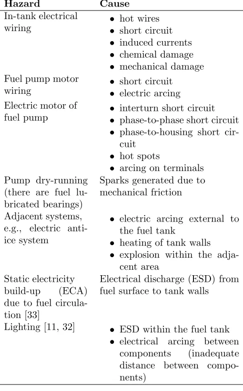
Table 2.4: Hazard and causes of fuel ignition in tanks.
Hazard Cause
In-tank electrical wiring
• hot wires
• short circuit
• induced currents
• chemical damage
• mechanical damage Fuel pump motor
wiring
• short circuit
• electric arcing Electric motor of
fuel pump
• interturn short circuit
• phase-to-phase short circuit
• phase-to-housing short cir-cuit
• hot spots
• arcing on terminals Pump dry-running
(there are fuel lu-bricated bearings)
Sparks generated due to mechanical friction Adjacent systems,
e.g., electric anti-ice system
• electric arcing external to the fuel tank
• heating of tank walls
• explosion within the adja-cent area
Static electricity build-up (ECA) due to fuel circula-tion [33]
Electrical discharge (ESD) from fuel surface to tank walls
Lighting [11, 32] • ESD within the fuel tank
• electrical arcing between components (inadequate distance between compo-nents)
is too lean to burn. When UFL is exceeded, the vapor space mixture is too rich in fuel to be flammable. When considering only equilibrium conditions, the particular fuel-to-air ratio, which can exist is determined by the temperature and pressure of the system. The tempera-ture determines the quantity of the fuel by controlling its vapor pressure, and the altitude determines the quan-tity of air. Therefore, by a suitable combination of tem-perature and altitude, under equilibrium conditions, the ullage of a fuel tank can be made either flammable or nonflammable [37].
As stated in Table 2.3, Jet A-1 fuel under static condi-tions and under 38◦C is typically not flammable. Small amount of fuel in the tank forms a very thin liquid layer across the bottom surface and is more dangerous than full fuel tank. Any heat input into this fuel layer can rapidly raise its temperature to above the flash point
of the fuel, thus forming combustible vapors in the ul-lage. Table 2.4 lists sources and causes of fuel ignition (explosion) in the tanks.
There are many factors that determine how and how much this heat transfer affects the fuel tank temperature and the flammability of the ullage space. These factors include the operational environment, flight operations, condition of the aircraft, the amount and temperature of fuel loaded in the tank, and other variables. In many cases, the fuel temperature is sufficiently high that the fuel-air mass ratio in the ullage space is above the lower flammability limit (fuel/air>0.03).
Figure 2.14: Flammability envelopes and estimated min-imum electrical ignition energies for Jet A/Jet A-1 and Jet B fuels [27].
Figure 2.15: Static and dynamic flammability envelopes for Jet A-1 and Jet B fuels [37].
igni-tion [33]. Electrostatic charge can develop due to fuel pumping, fuel splashing and fuel turbulence in the tank. The high electric potential between the surface of fuel and the metallic parts of tank can generate sparks, even though all structural parts of the tank are electrically connected together. This is called the electrostatic dis-charge(ESD) as a result of ECA. Pure hydrocarbons are essentially nonconductors. Kerosenes may have electric conductivity ranging from less than 1.0×10⁻¹² S/m to
20.0×10⁻¹²S/m at 20◦C. For comparison, the
conduc-tivity of deionized water is about 10.0×10⁻⁶S/m [25].
The higher the conductivity of fuel, the lower the prob-ability of sparks due to static electricity build-up. Mili-tary jet fuels and international Jet A-1 fuel require the use of additives that increase the electric conductivity of fuel [25].
The environmental parameters of temperature and al-titude which affect the flammability of the tank ullage, are illustrated by the so called flammability envelope. Traditional flammability envelopes have been available for many years [27]. The envelopes shown in Fig. 2.14 together with ignition energies, were derived by British Aerospace in the 1970’s [27]. It should be noted that the flammability limits are not specification requirements, which include instead flash point, vapor pressure, and distillation of the particular fuel type.
Under dynamic conditions (pressure and temperature transient), the flammability envelope extends towards lower temperatures, as shown in Fig. 2.15 [37]. The dynamic flammability envelope for Jet A-1 fuel shows, that the flash point at low altitudes is as low as 4 to 5◦C.
Auto-ignitionorignition temperature(Table 2.3) is the temperature at which the material will ignite on its own without any outside source of ignition.
2.8
Design of fuel tanks
Since the introduction of kerosene fuel for civil aircraft use in the late 1940’s, the aircraft designers have been aware that the ullage would contain a mixture of fuel vapor, or mist and air, which could be ignited in the presence of a spark, flame, or hot surface.
To prevent tank explosions, designers have always as-sumed a flammable vapor exists in the fuel tanks and adopted standards to preclude ignition sources from the fuel tanks. The following are some of the design mea-sures taken to satisfy that philosophy [27]:
A. Surface temperatures inside the tanks, under nor-mal and failure conditions, are kept at least 10◦C be-low the minimum necessary to ignite a fuel-air mixture. Pump motors are kept cool by an integral passage of circulating fuel. The motors have a temperature fuse, which cuts the electrical supply before an unsafe surface temperature is reached. In addition, the pumps and
other similar equipment inside the tanks, are designed and tested to explosion-proof standards. Bleed air pipes orelectric heating elements in the wing leading edge are frequently routed close to fuel tank walls. In such a case, heat-sensitive detector wires are installed to protect fuel tanks from overheat.
B. Electrical components and wiring within a fuel tank are designed to handle 1500 V AC which is well in excess of the voltage available on the airplane.
C. Electrical energy applied to any component in the fuel tank is limited to a value that is 10 times lower than the minimum energy necessary to ignite a fuel-air mixture. The minimum ignition energy (MIE) for hy-drocarbon vapors is about 0.25 mJ.
D. During the flow of ahydrocarbon type fuelthrough pipes, valves, filters, etc., anelectrostatic chargecan be generated in the fuel, which, if relaxed sufficiently fast, could allow the accumulation of hazardous potential lev-els inside a receiving tank. Therefore, it is necessary to avoid very high rates of fuel flow in the refueling system and control distribution of the fuel in the tanks (bot-tom loading and the use of diffusers on pipe outlets). In addition, meticulous attention is paid to electrical con-nection of all metallic parts to dissipate the charge. The use of special additives in the fuels to increase the fuel electrical conductivity is required in some countries.
A major consideration of fuel system safety is protec-tion against the effects of lightning [11, 27, 32]. When an aircraft is struck by lightning, a pulse of high current flows through the aircraft from the entrance to the exit points. Protection against this phenomenon is provided in a number of ways (well bonded structure of aircraft, thick wing skin panels, proper location of tank vents, etc.).
2.9
What could happen to the left
wing?
Only detailed investigation of the wreckage can an-swer the question what really happened to the left wing of the Tu-154M No 101. So far, the wreckage is not avail-able to independent investigators and only photographs taken at the crash site and wreckage storage site can be examined.
Careful examination of the crash site and description of debris immediately after crash could help to prove the hypothesis of fuel explosion. For example, a fuel pump (installed inside a fuel tank), if found in the debris field, would be a strong evidence of a fuel tank explosion.
for the formation of flammable vapors is larger. The explosion in the left wing tank No 3 could be a result of:
(a) ignition due to short circuit and arcing inside the tank No 3;
(b) fuel ignition due to static electricity build-up also called electrostatic charge accumulation (ECA); (c) explosion within the adjacent area of the left wing
tank No 3.
Malfunction of anti-ice electric heating system in-stalled in slats (Fig. 2.13) could lead to local temper-ature rise in the tank wall and create friendly conditions for fuel ignition by sparks or arcing. Fuel vapor auto-ignition due to local hot spot in fuel tank, or tempera-ture rise due to malfunction of anti-ice electric system or other electrical equipment/wiring is rather impossi-ble, since the auto-ignition temperature of Jet A-1 fuel is 210◦C (Table 2.3). More realistic iselectrostatic charge build-up (ECA) due to fuel flow and hazardous electric potential level inside the tank.
Explosion within the adjacent area due to other than electrical causes is very likely to happen [45].
There is also enigmatic statement in Annexure No 4 [15], Section 4.10.3, p. 3/5: At 05:59:005 UTC the flight recorders received a signal of failure or manual discon-nection of control and measurement of fuel consumption system SUIT4-1T. . . . The flight technician should im-mediately report all deviations in the fuel system to the aircraft commander. The cockpit voice recorder (CVR) does not show any evidence of such a report. It can be presumed that reconnection of control and measure-ment of fuel consumption system into manual mode was intentional. . . . However, the real cause of the reconnec-tion of the control and measurement of fuel consumpreconnec-tion system into manual steering mode remains unknown in this flight.
2.10
Conclusions
Although probability of explosion of fuel-air mixture in the left wing outer tank No 3 due the static electricity, electric short circuit or arcing is low, this problem cannot be neglected in further investigation of the accident, es-pecially examination of the wreckage, its remaining elec-trical equipment and left wing fuel tank No 3. Careful attention should be given to fuel pumps, electric motors for fuel pumps, electric anti-ice system of slats, all power cables/wires in fuel tank No 3 and in its vicinity.
The hypothesis of the second explosion in fuselage [45] could theoretically also be caused by explosion of fuel in the CWT.
Part 3:
Full-Scale Crash
Dynamic Tests of
DC-7 and LC-1649
Versus Hypothetical
Collision of TU-154M
with Birch Tree
3.1
Introduction
In 1964 full-scale dynamic crash tests on the DC-7 and Lockheed 1649 Constellation have been performed by the Federal Aviation Agency, USA, Aviation Safety En-gineering and Research, USA, and number of other agen-cies and organizations [40, 41]. The objective of these ex-periments wasexploration of the manner in which large aircraft are damaged in survivable accidents and accu-rate measurement of the crash loads [40, 41]. In the case of the DC-7, after collision with telephone poles, the tip of right wing finally fell off [17, 40]. This fact is frequently cited by supporters of the Tu-154M No 101 crash official reports [13, 29] as a proof that the collision of the Tu-154M No 101 with the trunk of a birch tree on April 10, 2010 near Smolensk North Military Air Base severed the tip of the left wing and finally caused fatal collision of the Tu-154M No 101 with the ground.
Figure 3.1: DC-7 test site and wing impact sequence. Telephone poles have been marked with blue color [40].
It is necessary to point out the following differences in:
![Figure 1.3: Main power distribution systems 115/220V AC and 36 V AC of Tu-154M. 1 - rectifiers VU-6A(backup and No 1), 2 - rectifier VU-6A No 2, 3 - rightjunction box (JB) 115/200 V, 4 - converter PTS-250 No2, 5 – converter PTS-250 No 1, 6 – JB of kitchen, 7– JB of anti-ice system, 8 – right panel of generators,9 – generator GT40PCh6 No 3, 10 – JB of APU 200V, 11 – generator GT40PCh6 of APU, 12 – generatorGT40PCh6 No 2, 13 – generator GT40PCh6 No 1, 14– external power connector for ShRAP-400-3F GPU, 15– left panel of generators, 16 – left JB 115/220 V, 17 –transformer No 2, 18 – transformer No 1, 19 – right JB36 V AC, 20 – left JB 36 V AC, 22 - flight attendantswitchboard, 23 – converter POS-125TCh [49].](https://thumb-us.123doks.com/thumbv2/123dok_us/8374797.1676479/3.612.102.246.82.190/distribution-rectiers-rectier-rightjunction-generatorgt-transformer-transformer-attendantswitchboard.webp)

![Figure 2.4: Construction of the Tu-154 wing [52].](https://thumb-us.123doks.com/thumbv2/123dok_us/8374797.1676479/15.612.61.292.493.643/figure-construction-of-the-tu-wing.webp)
![Figure 2.8: Wiring configuration on the Boeing 747. In-vestigators suspect that high voltage from the fuel flowmeter A passed to the fuel quantity indication system(FQIS) B because of a short circuit in the wire bundle[34].](https://thumb-us.123doks.com/thumbv2/123dok_us/8374797.1676479/16.612.307.564.262.346/figure-conguration-boeing-vestigators-suspect-owmeter-quantity-indication.webp)

![Table 2.3: Characteristics of fuel Jet A-1 [25]](https://thumb-us.123doks.com/thumbv2/123dok_us/8374797.1676479/19.612.318.556.474.625/table-characteristics-of-fuel-jet-a.webp)
![Figure 3.1: DC-7 test site and wing impact sequence.Telephone poles have been marked with blue color [40].](https://thumb-us.123doks.com/thumbv2/123dok_us/8374797.1676479/22.612.332.541.490.622/figure-test-impact-sequence-telephone-poles-marked-color.webp)
![Figure 3.3: LC-1649 full-scale dynamic crash test. In-board pole impact [41].](https://thumb-us.123doks.com/thumbv2/123dok_us/8374797.1676479/23.612.350.522.82.191/figure-scale-dynamic-crash-test-board-pole-impact.webp)
