http://www.sciencepublishinggroup.com/j/ijem doi: 10.11648/j.ijem.20170101.13
Case-Based Reasoning for Building Structures: A Case
Study of Timber Floor Slabs Strengthening
Ana Fernández-Cuartero Paramio
1, Juan Francisco de la Torre Calvo
2, Antonio Aznar López
2,
José Ignacio Hernando García
2, Consolación Acha Román
1, Fernando da Casa Martín
31
Departamento de Construcción y Tecnología Arquitectónica, Escuela Técnica Superior de Arquitectura, Universidad Politécnica de Madrid, Madrid, Spain
2
Departamento de Estructuras y Física de la Edificación, Escuela Técnica Superior de Arquitectura, Universidad Politécnica de Madrid, Madrid, Spain
3
Departamento de Arquitectura, Área de Construcciones Arquitectónicas, Universidad de Alcalá de Henares, Madrid, Spain
Email address:
[email protected] (A. Fernández-Cuartero Paramio), [email protected] (J. F. de la T. Calvo),
[email protected] (A. Aznar. López), [email protected] (J. I. H. García), [email protected] (C. A. Román), [email protected] (F. da C. Martín)
To cite this article:
Ana Fernández-Cuartero Paramio, Juan Francisco de la Torre Calvo, Antonio Aznar López, José Ignacio Hernando García, Consolación Acha Román, Fernando da Casa Martín. Case-Based Reasoning for Building Structures: A Case Study of Timber Floor Slabs Strengthening.
International Journal of Engineering Management. Vol. 1, No. 1, 2017, pp. 16-26. doi: 10.11648/j.ijem.20170101.13
Received: March 13, 2017; Accepted: March 30, 2017; Published: April 27, 2017
Abstract:
This article presents the application of a Case-based Reasoning (CBR) in order to define the calculation and verification parameters to design building structures. Each and every calculating variable has to be chosen according to construction criteria from a set up list. These decisions are meant to find a solution that will be the closest possible to a valid one, and this will be verified through calculation. In the optimal scenario, the calculation will just verify that the chosen solution is valid, or that it is completely impossible to implement the strengthening; whereas in the worst scenario, the calculating process will simply correct some previous decision, once the strengthening suitability is confirmed. A case study of timber floor slabs straightening is introduced in which a selection of the necessary parameters for its calculation and verification are defined by CBR. Finally, the same case study is built and calculated by SAP commercial program in order to find out whether the defined parameters can actually envisage a proper solution for the strengthening.Keywords:
Case-Based, Reasoning, Floor-Slab, Strengthening, Timber1. CBR Purpose
The objective of this essay is presenting the possibility of a Case-based Reasoning (CBR) acting like a translator between the qualitative and geometrical data of a floor slab, and the quantitative data required by a conventional calculating program. Therefore, the output of the translator would be the input in the calculating process. Another aim of this piece of work, is also pointing out the fact that the quantitative data could include an initial proposal for the strengthening.
1.1. CBR
The delimiting data can be arranged into three main families: a) the one that defines the strengthening construction materials, b) the one that defines the geometry
and the mechanical characteristics of the existing floor slab, and the strengthening to be done; and c) the one that defines the loads to be considered in the calculation of the strengthening, taking into account the site and the polishing and the use.
premises that can be gathered together and connected with a CBR [1, 2].
1.2. Methodology: Analysis of the Data Required for the Strengthening
In order to study the use of CBR for obtaining input data required by calculating programs, it is necessary to enumerate and differentiate the data families [3, 4]. According to the order in which they are taken into account, they can be separated into three main families, as mentioned above. Each family includes many items according to the scheme:
Materials 1.Wood 2.Concrete 3.Bond steel
4. Connectors 5. Geometry
Thickness of the concrete layer 1. Reinforcement
2. Screws Load
1. Self-weight 2. Finishing 3. Partitions 4. Use
5. Climate actions 6. Load combinations
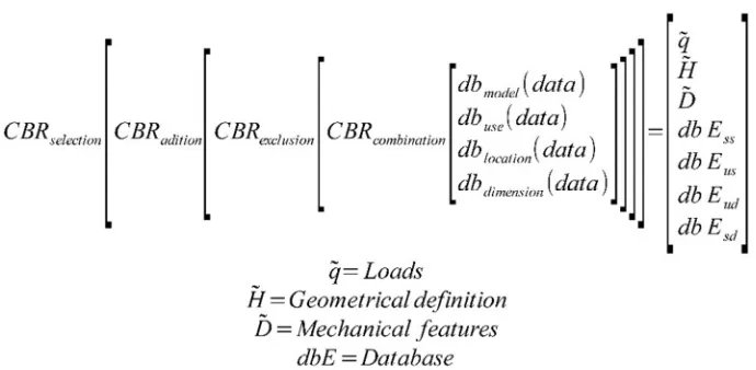
There are several decision rules [5, 6], which will relate databases and fence in the values for all the families as shown in figure 1.
Figure 1. Decision rules use by the CBR to relate the data and fence in their values.
The algorithm defined in figure 1 is able to obtain a valid solution, which could be corroborated by conventional analysis. Then, it can be considered the optimum one, or it can be used to obtain a more exactly solution.
There are several examples of application of CBR in construction; some of them [7-11] must be noted. A complex structural model can be defined by CBR translator [12] and it can be later this will be verified through calculation. In this case, the solution obtained must be similar to the results obtained calculating by commercial analysis program, in which the input data must be defined in a conventional way.
This paper present an example of this comparison, focused on the timber floor slabs strengthening.
In order to value the suitability of the solution obtained by the CBR presented in this work, a case study is presented below. The solution obtained by the commercial analysis program SAP of no-linear model of finite elements method is evaluated. The results of this analysis allow evaluating the initial solution obtained by CBR.
2. Case Study
The case study of this work consists in a timber floor slab strengthening. The main parameters are summarized below:
Location: Manjabálago, Ávila, Spain. Slab Geometry:
Span length: 4,00 m Cantilever length: 0,80 m Joists Section:
Joists (width x high): 110x140 mm Distance between two joists: 0,40 m Longitudinal/transversal slab angle: 0,00º Model definition and use:
Wooden joists and ceramic infilling Slab section high: 0,20 m
Slab finishing: Ceramic tiles Use: dwelling use
Load on cantilever: Masonry railing Environmental conditions:
Type of construction: Building inner Concrete exposure: No condensations Chemical aggressiveness: None
2.1. Introduction
The vast majority of the Spaniard heritage prior to the XX century is built with timber floor slabs, sometimes combined with ceramics or stone.
normally consist on timber joists settled in between an ordinary wall and a load bearing wall, and ceramic infilling without any compression layer [13, 14]. The timber joists bear all the structural effort, whereas the ceramic infilling transmit the load to the timber joists and give stability to the whole floor slab. Furthermore, the floor slab would only take in one single span because it would help the transport, the manual process of construction and because there was always a limit of length fixed by the tree height.
The strengthening of floor slabs is a very frequent rehabilitation process due to the use load changes, the overload caused by the modification of the finishing and often to the creep deflection of the material [15]. Wood has a high durability; therefore, with a simple strengthening it is possible to enable it (without causing any resistance nor deflection problems) to bear loads in compliance with current legal standards.
First of all, it is necessary to decide whether the strengthening will be displayed on the upper side of the floor slab or underneath it. In this particular case, we will study the first type mentioned which will consist on a concrete slab fixed to joists by steel screws that will make up a composite timber-concrete structure.
2.2. Design Using CBR
First of all we will study the type mentioned which will consist on a concrete slab fixed to joists by steel screws that will make up a composite timber-concrete structure (figure 2). Although this kind of structures is not very frequent, it has been proved that they seem very efficient (for both building and civil engineering). In the work [16] authors show the efficiency and the good performance of composite timber-concrete structures that comply with the Eurocode 5 [17] and Nch1198 Standards [18]. They also validate the calculating model by obtaining even better results in tube tests than the ones expected in theory. In our case, despite not being rather spread the use of composite timber-concrete structures for new built floor slabs, this combination allows using the existing wood in historical buildings, blending it with concrete, and bonding them both with screws. This first decision (the display of the strengthening) already enters into the CBR; and since we are not creating a new kind of strengthening, we will choose an existing one; hence, taking advantage of the knowledge experience provides us with.
Figure 2. Concrete slab strengthening for timber joists floor slabs.
2.2.1. Materials by CBR
The main characteristics of the chosen materials will
a. Wood. Since wood is the existing material in the floor slab, it will be necessary to keep within the fixed data. If the type of wood is unknown, statistics and knowledge of the main materials used within the area will enclose the type used in the calculation. If there is not particular data, the most commonly used will be chosen. In Spain, pinewood C18 is the most frequent.
b. Concrete. When it comes to concrete, three choosing criteria must be taken into account:
i. Standards: the Spaniard Standards for reinforced concrete structures establish HA25 as the minimum for any structural concrete. (Art 39, section 39.2 of EHE08 [19])
ii. Regular use: in the vast majority of concrete construction, HA25 is the most used.
iii. Efficiency: in favour of efficiency not only do we have the price, but also the regular use. In this case, both lead to a fast supply of the material.
As it has been shown, the three criteria agree on the same type of concrete. Therefore, it is not required to establish more rules for this material. The minimum set by the law coincides with the cheapest one which is the most commonly used.
c. Bond steel. As it happened with concrete, there are also three relevant criteria for picking the accurate type of corrugated steel.
i. Standards: depending on the steels resistance, B400S and B500S (Art 32, Table 32.2. a of EHE08 [19]).
ii. Regular use: B500S is the most used.
iii. Efficiency: the same type of bond steel would be chosen, for there is not a remarkable difference on its price.
According to the three criteria, B500S is the most interesting one. Because, even though it exceeds the capacity needed, it is the most available at a similar price.
d. Connectors. (Screws) when it comes to decide the type of steel for the connecting screws, the same three criteria are taken into account:
i. Standards: the following types are established –from the lowest to the highest resistance-: 4.8, 5.6, 6.8, 8.8 and 10.9
ii. Regular use: unknown. There is not any kind of steel most commonly used.
iii. Efficiency: types 4.8, and 5.6 should be rejected, since they are the weakest and it would be necessary to use a big amount of them (therefore causing a delay in the construction). The opposite happens with types 8.8 and 10.9, as they would be underutilized for being excessively resistant. Thus, choosing a halfway type would be the best option in terms of efficiency.
In conclusion, according to criteria based on market knowledge, standards, and efficiency, the materials for the strengthening have been selected: HA25, bond steel B500S and 6.8 screws.
2.2.2. Geometry of the Strengthening
Once we have chosen the type of strengthening (an upper side one in this case study) and the characteristics of the constructing materials, next step would be delimiting the data referred to the geometry of the strengthening. Both the wood
section dimensions and the separation between joists are fixed data.
The geometry of the strengthening is defined by the thickness of the concrete layer, the diameter and the separation between the steel rebars, and the disposal of the screws.
a. Thickness of the concrete layer: following the example settled when choosing the material characteristics, we will include the same three criteria: standards, regular use and efficiency.
i. Standards
When it comes to covering, there should be 30mm at each side of the reinforcement, thus 60mm in total.
If the minimum aggregate is 20mm, the thickness ought to be 2.5 times the diameter, thus 50mm in total.
Thickness must be at least 1/10 of the joists gap.
ii. Regular use: it is hard to cast the concrete if the thickness is below 50mm, therefore, it is convenient to surpass this measure.
iii. Efficiency: if we need to surpass 50mm, it is best to add 20mm, thus settling the optimal thickness at 70mm.
The decision rule is 70mm, as it fulfils all requirements. b. Reinforcement (Rebars): according to the criteria: i. Standards: geometric quantity: for HA25 is 1.1‰ in transversal direction to the joists, and 0.6‰ in parallel direction. Normalized diameter of the bars: 6, 8, 10, 12, 14, 16, 20, 25, 32, 40 (Art. 32 of the EHE08 [19]).
ii. Regular use: the most frequent is, in slabs, gaps of 100, 125, 150, 175, 200, 250 and rebars of 8mm maximum diameter. For obtaining a better performance, do not set less than three bars per linear meter.
iii. Efficiency: all types are suitable. In particular, diameters 6, 8 and 10 are optimal for 70mm thickness determined previously.
The decision rule is the one that complies with all requirements, which coincides with the one called for the minimal transversal and longitudinal quantity –to the joists-. In this case, longitudinal (1.1‰) 77mm2 and transversal (0.6‰) 42mm2, this is, a steel bar of 6mm in longitudinal direction and two in the transversal one, but since it is not frequent to set less than three per meter, we shall set –in both directions- a steel bar of 6mm every 30cm.
c. Screws: according to the same criteria:
i. Standards: legal requirements set a minimum distance inbetween screws, and between a screw and the edge, to avoid wood tearing.
ii. Regular use:
- There are screws available in the market with diameters 6, 8, 10, 12, 14, 16, 20, 22, 24, 27 and 30.
- Penetration tends to be 8 times the diameter, and not more than ¾ of the joist cross-section height.
Figure 3. Screws on a wooden joists floor slab strengthening.
The decision rule that meets all requests is bounded to the dimensions of the joist. For instance, in a 140x110 joist, screws (figure 3) would be of 8mm diameter, or if doubled, 4mm diameter.
Nevertheless, there is a wide range of possibilities than can only be solved by mechanical calculation. There is not a previous decision taken but diameter and minimum distances. These conditions lead us to a strengthening defined in terms of materials and dimensions. Therefore, the joist dimension is the only initial given data, which is independent from the CBR, but taken into account in it for further definitions of remaining parameters to be defined by the CBR procedure.
This is the minimal strengthening, and thus the optimal. If it turns to be valid once calculated, this will be the chased solution.
2.2.3. Load Calculation
The next step is determining the system of loads that will be needed for calculating the strengthening. This system of loads is a matter of construction and standards, since the strengthening materials and use of the floor slab define it.
Types of loads: we can classify loads according to the strengthening morphology, to its finishing or the coating they have to bear, to its position in the building (floor or roof), and to its use, into:
Self-weight (dead load) Finishing (dead load) Partitions (dead load) Use (live load)
Climatic load (live load)
a. Self-weight: it is a permanent load derived from the constructive solution.
The CBR determines the numerical value of this load through the constructive definition taking into account a database that includes all frequent solutions and their weight.
For instance, “timber joists floor slab + 15cm edge beam fill + compression layer”. There is no decision rule; instead, the value is taken from the database directly.
The load is:
Self-weight of the floor slab = weigh/m3 of the floor slab + e (thickness of edge in meters) + weight of the compression
layer.
Load of the floor slab: 2KN/m2
b. Finishing: again, the finishing or covering of the floor slab is a permanent load defined by its material and its thickness. It is a fixed data, which comes not from a decision rule, but directly from the calculation of the materials density and the thickness of the layer displayed on the floor slab.
In several cases, the CBR allows us to select a multiple layer finishing – take for instance, a ceramic tile roof along with a timber deck- without having to select a specific thickness, for it is common to work with fixed thicknesses, and therefore, fixed weight per area unit as well.
A floor slab formed by a tile flooring arranged on a levelling layer, with total thickness 5cm, would have a weigh of:
Finishing weight = 0.8 KN/m2
c. Partitions: it is considered separately from the previous weights. However, it can be treated as an overload or as a dead load according to the Spaniard Standards for building structures CTE-DB-SE-AE [20].
The standards determine the minimum values, but the particular construction can bring up other data. In order to calculate this load, the decision rule will be choosing the highest one, as long as it does not conflict with the use load.
Generally, the partitions load of a dwelling-use floor slab like the one described previously would be 1KN/m2.
d. Use: CTE-AE Regulation defines very accurately the use load. However, it can also be determined by the characteristics of a particular construction. Again, the decision rule is choosing the highest among them both.
If, as described before, we are working with a dwelling-use floor slab:
Use load = 2KN/m2.
e. Climatic actions: these are derived from the effect of snow and wind on the roof slab, and depend on two objective conditions: geographic location and topography, gathered in the standards; and another geometrical condition which is the roof slope –necessary to calculate the wind effort-.
They are direct data, thus there is no need to apply any decision rule, and we only need the roof slope and to have access to a database containing the standards requirements.
For example, if the roof slab is located in a building in Ávila (Spain), the snow load is a fixed data of 1.10KN/m2 measured in horizontal projection, whereas the wind load is 0.42KN/m2. Wind load has to be multiplied by a pressure coefficient Cp and an exposure coefficient Ce. The live load
for use is 1KN/m2 maximum.
2.2.4. Load Combinations
There are three types of decision rules; all of them based on the standards:
1.Addition rule 2.Exclusion rule 3.Combination rule
Since roof slabs and floor slabs bear different loads (whose consideration varies as well), the decision rules applied to each case will be distinct.
Figure 4. Combination of loads regarding resistance on floor slabs.
2.2.5. Resistance
In order to calculate the floor slab’s resistance, it is
necessary to choose the most adverse load combination, as can be observed in figure 4.
For floor slabs: Loads: Self-weight Finishing
Partitions Use
Partial rules of addition and exclusion, and general rule of addition.
For roof slabs: Loads: Self-weight Finishing
Use
Climatic actions
Addition rule, exclusion rule, and general rule of addition (figure 5).
Figure 5. Combination of loads regarding resistance on roof slabs.
Among use, wind and snow loads: general exclusion rule, and rule of exclusion between both climatic loads (wind and snow). It is particularly relevant in the case of light roofs, since the wind suction could lift them.
Moreover, load weighting coefficients are included; according to the Spaniard Standards, 1.35 for permanent load, and 1.50 for variable and climate load.
2.2.6. Deflections
When it comes to calculating deflections, the simultaneity of loads among the floor slab is the main factor taken into account, whereas load weighting coefficients are not included.
It is essential to define three basic deflection concepts. The load values to be selected for them all will be different from one another:
Total deflection
Live deflection due to use loads
Live deflection due to rheological effects
Again, we shall bear in mind if it is a floor slab or a roof slab that we are working with for calculating its deflection.
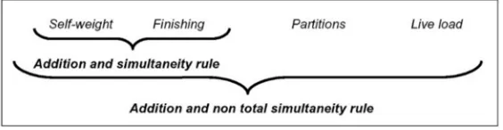
i. Floor slabs i.1. Total deflection
Loads (represented in figure 6): Self-weight Finishing
Partitions
Use (depending on the type of use there might be simultaneity or not)
Partial rules of addition; and addition rule without total simultaneity.
Figure 6. Combination of loads regarding deflection on floor slabs.
Maximum deflection: stablished on the standards. i.2. Live deflection due to use loads
There is no simultaneity of loads nor coefficients; as only use load are included.
Maximum deflection: stablished on the standards.
i.3. Live deflection due to rheological effects. The figure 7 shows the ratio between the deflection of a just built floor slab with finishing and the deflection along time calculated at point 1 (Total deflection).
The initial deflection comes from:
Figure 7. Combination of loads regarding deflection due to rheological effects on floor slabs.
Live deflection due to rheological effects = Relation rule: Total deflection - Initial deflection.
ii. Roof slabs ii.1. Total deflection Loads: Self-weight Finishing
Climatic loads (wind/snow) Use
Standards: for climatic actions, there are several simultaneity coefficients:
Ψ0 roof = 0 (for roof with no use)
Ψ0 wind = 0.6
Ψ0 snow = 0.7
Considering that climate actions exclude one another, normally the snow coefficient is more unfavourable in mountain areas, whereas in plain and exposed lands the wind coefficient is the most adverse (figure 8).
Addition rules, exclusion rules, and addition rules without simultaneity.
Figure 8. Combination of loads regarding deflection on roof slabs.
Maximum deflection: stablished on the standards. ii.2. Live deflection due to use loads
For there are several different ones (use, climate, etc.), exclusion rule has to be applied (in order to choose the highest one).
Maximum deflection: stablished on the standards. ii.3. Live deflection due to rheological effects.
It is the ratio between the deflection of a just built floor slab with finishing and the deflection along time calculated in point 1.
Addition rule and simultaneity: self-weight + finishing Just like in the case of live deflection due to rheological
effects in floor slabs, when it comes to roof slabs, the same criteria is applied (represented in figure 7).
Live deflection due to rheological effects = Relation rule: Total deflection – Initial deflection
With the data referring to the constructing materials, geometry and loads, we would have all the fixed numerical values required for calculating the floor slab.
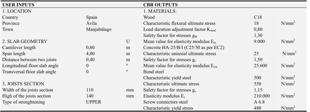
Taking into account all the given information, the following table shows the user’s input data and the CBR output data. We are dealing with a timber floor slab strengthening in a dwelling house located in Manjabálago town, Ávila, Spain (table 1).
Table 1. Input data and CBR output data.
USER INPUTS CBR OUTPUTS
1. LOCATION 1. MATERIALS:
Country Spain Wood C18
Province Ávila Characteristic flexural ultimate stress 18 N/mm2
Town Manjabálago Load duration adjustment factor Kmod 0,80
Safety factor for stresses gM 1,30
2. SLAB GEOMETRY U Mean value for elasticity modulus Em 9.000 N/mm2
Cantilever length 0,80 m Concrete HA-25/B/I (C25/30 as per EC2)
Span length 4,00 m Characteristic uniaxial ultimate stress 25 N/mm2
Distance between two joists 0,40 m Safety factor for stresses gc 1,50
Longitudinal floor slab angle 0 º Mean value for elasticity modulus Ecm 25.600 N/mm2
Transversal floor slab angle 0 º Bond steel
Characteristic yield steel 500 N/mm2
3. JOISTS SECTION Characteristic ultimate stress 550 N/mm2
Width of the joists section 110 mm Safety factor for stresses gs 1,15
High of the joists section 140 mm Elasticity modulus Es 210.000 N/mm2
Type of strenghtening UPPER Screw connectors steel A 6.8
USER INPUTS CBR OUTPUTS
5. MODEL DEFINITION AND USE Characteristic ultimate stress 600 N/mm2
Type of slab Wooden joists and ceramic
infilling Safety factor for stresses gm 1,25
Slab section high 0,20 m Elasticity modulus Es 210.000 N/mm2
Slab finishing Ceramic tiles
Slab finishing high 0,05 m 2. STRENGHTENING GEOMETRY
Use A1 Dwelling use Concrete layer thickness 70 mm
Load on cantilever Masonry railing Longitudinal rebars diameter Φl 6 mm
Longitudinal rebars gap sep_l 200 mm
6. AMBIENT CONDITIONS Transversal rebars diameter Φt 6 mm
Type of constructiion Building inner Transversal bars gap sep_t 250 mm
Concrete exposure No condensatios Screws diameter 4 mm
Chemical agressiveness None Number of screws 2 u
3. LOADS
Loads per slab m2 and cantilever
Use load 2,00 kN/mm2
Partitions load 1,00 kN/mm2
Slab self-weight 2,76 kN/mm2
Finishing load 0,80 kN/mm2
Load on cantilever 2,25 kN/mm2
Loads per joint
Concentrated permanent load on cantilever 0,90 kN
Permanent load on cantilever 1,82 kN/m
Permanent load on joist 1,82 kN/m
Punctual variable load on cantiilever 0,80 kN
Variable load on joist 1,20 kN/m
Variable load on cantilever 1,20 kN/m
Resistance
Load weighting coefficients
γG 1,35
γQ 1,50
Deflection Wood
Class 1,00
Rheological moisture creep factor kdef 0,60 Concrete
Creep and srinkage factor φ 2,50
Simultaneity coefficients: I=1 I=2
ψ0 use 0,70
ψι use 0,50 0,30
Deflection maximum values:
Total deflection 1/300
Live deflection 1/500
The calculation will corroborate the CBR solution as effective, or will modify certain data in order to get closer to the valid solution. This modification will adjust the new values to the next-higher ones, thus obtaining the optimal solution at once.
2.3. Design Using SAP
With the foresaid data provided by the CBR rules, a FEM
model has been created, as can be observed in figure 9. As CBR rules just provide geometrical data and timber and concrete data, no bond steel reinforcement has been considered in the model. Same happens to screw connectors, that have been neglected as well. Bond steel is not considered in order to not overestimate the stiffness of the system and screw connectors are not totally defined by the CBR rules.
Figure 9. Image or 3D FEM model.
Applied loads, coefficients and all other data are as listed on the table previously shown.
2.3.1. Analysis Details
figure 10 and figure 11 for timber and concrete respectively.
Figure 10. Stress-strain law for timber.
Figure 11. Stress-strain law for concrete.
Two different hypotheses have been observed: with serviceability values for loads (SLS) and with design loads (ULS). The first one will give us information on deformations and deflections and the second information on stresses. As rheological effects are important both for timber and concrete, values have been retrieved for initial conditions and final conditions, being these last the ones taking into account rheological effects.
As connection is not defined, the bond between timber and concrete has been restricted to the midline of the upper layer of timber joists. This means than shear efforts and
deformations will be the biggest possible, so the decision does not make any fictions structural improvement.
For initial and final rheological conditions, the following results have been retrieved from the model:
1.Vertical displacement at mid-span (SLS) (figure 12) 2.Normal stresses at timber joists (ULS) (figure 13) 3.Normal stresses at the concrete layer (ULS) (figure 14)
2.3.2. SAP Results
For the initial conditions, the graphical results are as follow:
Figure 13. Axial stress at timber joists (kN/m2).
Figure 14. Normal stresses at the concrete layer (kN/m2).
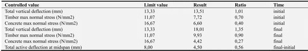
By retrieving values for initial and final conditions, a comparison can be made with the limits under which the design must work. Results are exposed in table 2:
Table 2. Results provided by the FEM model referred to limit values.
Controlled value Limit value Result Ratio Time
Total vertical deflection (mm) 13,33 13,51 1,01 initial
Timber max normal stress (N/mm2) 11,07 7,72 0,70 initial
Concrete max normal stress (N/mm2) 16,67 6,60 0,40 initial
Total vertical deflection (mm) 13,33 18,01 1,35 final
Timber max normal stress (N/mm2) 11,07 9,93 0,90 final
Concrete max normal stress (N/mm2) 16,67 4,42 0,27 final
Total active deflection at midspan (mm) 8,00 4,50 0,56 final-initial
3. Comparison
This paper shows the design of a case study using both CBR and SAP. The main differences between these two methods are the definition of the input data. The finite elements method needs every geometrical and mechanical value. On the other hand, CBR only need constructive parameters.
3.1. Differences between FEM model and CBR Solution
When comparing the values actually obtained by the nonlinear FEM model, just taking into account the initial data provided by the CBR rules, it comes out that the design so far provided fulfils almost all final conditions to be imposed to the final design. Only the total deflection at final time is out of range, and stresses in concrete and timber are well controlled: timber gets a maximum ratio of 0'90 (thus getting a big profit from its structural capacity) and concrete has an upper ratio of 0'40, which matches well with the condition for applying Navier's theory to deflection calculations in concrete that maximum stress on it should not go over a ratio of 0'45.
Therefore, the solution provided by the CBR rules will satisfy the conditions imposed with very small changes. Mainly, deflections have been overestimated on the FEM model, due to the lack of bond steel in the concrete layer,
which is provided by the CBR rules but has been neglected. Therefore, if bond steel had been considered the stiffness of the composite section would have been bigger, due to a higher neutral axis, providing a bigger inertia. In addition, this bond steel would have imposed a limit to the creep and shrinkage effects on the concrete layer in the long run, thus dismissing the compressive strains of it, providing less deflections at the mid-span point. Therefore, the complete solution including bond steel, starting from the solution given by the CBR rule, will be the initial solution with just little additions, but basically the CBR solution is fully satisfactory.
3.2. CBR Advantages
The main advantage of CBR is that it is able to obtain a solution without calculating everyone of the value of input data. CBR is able to translate the qualitative and geometrical data to the corresponding values of materials, geometry and loads.
Table 1 shows how CBR generate several numeric data (column 4) only using construction criteria. In this way, a final results can be obtained using CBR with a significantly simplification, compared with analysis using standard programs.
4. Conclusions
value for a specific timber floor slab strengthening. In order to do so, it requires a database containing all loads linked to the different regular constructive systems, most efficient strengthening materials or systems, and the values specified in the standards. All these numbers are also sorted in the database.
With all this data, it is necessary to stablish the CBR decision rules that will select the correct value for every geometrical and mechanical parameter, and for all loads in every calculating hypothesis. Furthermore, these rules will comply with the technical standards, constructive use, and the defined limits. The rules will sort out, among the different choices, a final data that will be the input in the calculation kernel.
Therefore, if the initial value (regarding geometry and quality of the materials) is correct, the given solution will be optimal, since it will be the most adjusted within all the possible solutions. This is, it will be the most efficient one: less quantity of material, faster performance and fewer costs.
References
[1] Huo, D., Li, W. Z., Zuo, Y. Z., Liu, Y. M., & Zhou, L. Y. (2013). “Detection Analysis of Steel Structural Damage Based on CBR”. Journal of Beijing University Technology, 39, 570-575.
[2] RunZhi, J., Sangwon, H., ChangTaek, H., & JiHoon, K. (2014). “Improving accuracy of early stage cost estimation by revising categorical variables in a case-based reasoning model”. Journal of Construction Engineering and Management, 140, 04014025. doi: 10.1061/(ASCE)CO. 1943-7862.0000863.
[3] Clarke, R. (1988) Knowledge Based Expert Systems. Accesible at: http://www.rogerclarke.com/SOS/KBT.htlm [4] Castro, J. L., Navarro, M., Sánchez, J. M., Zurita & J. M.
(2010). “Introducing attributive risk for retrieval in case-based reasoning”. Revista de aplicaciones de sistemas expertos basados en el conocimiento. Especialmente, para los fines que se persiguen en este sistema, 24, 257-268.
[5] Yejun Xu, Qingli Da. (2008). “A method for multiple attribute decision making with incomplete weight information under uncertain linguistic environment”. Knowledge-Based Systems, 21, 837-841.
[6] Yuanping Xu, Zhijie Xu, Xiangqian Jiang, & Scott, P. (2010) “Developing a knowledge-based system for complex geometrical product specification data manipulation”.
Knowledge-Based Systems, 24, 10-22.
[7] J. H. M. TAH, V. CARR, R. HOWES, (1998) "An application
of case-based reasoning to the planning of highway bridge construction", Engineering, Construction and Architectural Management, Vol. 5 Iss: 4, pp.327 – 338.
[8] EDIZ ALKOC, FUAT ERBATUR, (1998) "SITE EXPERT: a prototype knowledge-based expert system", Engineering, Construction and Architectural Management, Vol. 5 Iss: 3, pp.238 – 251.
[9] ShiHai, Z., & JinPing, O. (2013). “BP-PSO-based intelligent case retrieval method for high rise structural form selection”.
Science China: Technologies Sciences, 56, 940-944. doi: 10.1007/s11431-013-5167-8.
[10] Konczak, A., & Paslawsky, J. (2013). “Abductive and Deductive Approach in Learning from Examples Method for Technological Decision Making”. Modern Building Material, Structures and Techniques, 57, 583-588.
[11] Jing, D. & Bormann, J. (2014). “Improved similarity Measure in Case-Base Reasoning with Global Sensitivity Analysis: An Example of Construction Quantity Estimating”. Journal of Computing in Civil Engineering, 28, 04014020. doi: 10.1061/(ASCE)CP. 1943-5487.0000267.
[12] Kartelj, A., Surlan, N., & Cekic, Z. (2014). “Case-based reasoning and electromagnetism-like method in construction management”. KYBERNETES, 43, 265-280. doi: 10.1108/K-06-2013-0105.
[13] James D., (1998) "The development of ground floor constructions: part 5 (damp proofing existing ground floors)", Structural Survey, Vol. 16 Iss: 3, pp.136 – 140.
[14] A. Cruden, (1990) "Fort George rehabilitation – Case study on timber strengthening", Structural Survey, Vol. 8 Iss: 1, pp.31 – 43.
[15] Macías Bernal, J. M., Calama Rodríguez, J. M., Chávez de Diego, M. J. (2014). “Modelo de predicción de la vida útil de la edificación patrimonial a partir de la lógica difusa”.
Informes de la construcción del Instituto Torroja, 533. [16] Cárdenas, M., Schanack, F. & Ramos, O. R. (2010). “Design,
construction and testing of a composited glued timber-concrete structure to be use in bridges”. Revista de la construcción, 2, 63-65.
[17] European Committee for Standardization., & British Standards Institution. (1994). “Eurocode 5: Design of timber structure”. Brussels: BSI.
[18] Instituto Nacional de Normalización INN-Chile. 1999. NCh 1198. Of91 Madera. Construcciones en madera. Cálculo. INN, Santiago.
[19] EHE. Real Decreto 1247/2008. Ehe-08. Instrucción del Hormigón Estructural. 2008.