VLSI Implementation of Lifting Based 3-D
DWT
M.Prethippa
#1, N.Usha Bhanu
*2#1
M.E Communication System, Valliammai Engineering College SRM nagar, Kattangulathur, *2
Assitant professor, valliammai engineering college SRM nagar, kattangulathur.
Abstract -This paper proposes an efficient architecture for lifting based 3-D DWT Lifting based for video/ image signal using parallel pipeline technique. The main objective of this paper is to minimize the critical path delay in computing the 9/7 lossy lifting steps with reduced clock cycles. The architecture consists of row, column and temporal processors and video frames are processed using separability and cyclic symmetry property. The novelty of this method is by using flipping structure for adders and replacing multipliers by shift and add operations. This benefits the proposed method for low latency, power consumption, and high throughput over many existing architectures. To validate this model, the architecture is being coded in Verilog HDL and implemented using Xilinx ISE 14.7xc7a100t-3-csg324 FPGA. The performance of this architecture of 3D lifting DWT processor achieves a speed of at least 373 MHZ with low power dissipation making it suitable for real time high speed video applications.
Keywords: Lifting DWT, Parallel processing,Cyclic symmetry Property, Critical path delay, Video processing, pipelining.
I. INTRODUCTION
The Discrete Wavelet Transform posses multi resolution capability which has adjustable locality in both the time and frequency domains. When compared to the Fourier transform, the wavelet transform has many possible sets of basis functions [2]. The image compression technique based on 2-D Discrete Wavelet Transform is superior over existing JPEG based on Discrete Cosine Transform and is standardized in forms like JPEG2000 as discussed in [12]. The DWT supports features like progressive image transmission, ease of compressed image manipulation, region of interest coding, etc, as discussed in [15]. The hardware implementation of DWT increases the computational complexity of the DWT. Therefore, the suitable VLSI implementations of lifting DWT is inevitable for real time image/video applications.
DWT process can be implemented by convolution technique and lifting based methods [16]. The main disadvantage of the convolution technique is only applied for frequency domain and in additional, they require extra storage memory. The hardware implementation of lifting-based DWT has many advantages like in-place computation, integer-to integer transform, reduction of the number of arithmetic operations, the size of registers, and overcomes the limitations of convolution technique. The previous existing architectures are designed for fixed processing speed and cannot be extended to achieve a higher processing speed for video processing [17]. Simulation of 3-D lifting DWT requires higher computational complexityand memory. computational and the objective of this paper is to propose an efficient VLSI architecture for lifting DWT without multipliers, therefore reducing the critical path delay suited for real time multimedia applications.
This paper proposes an optimized 3-D DWT lifting method using parallel pipeline processing and to minimize a critical path delay. The pipelining and parallel processing is done for row, column and temporal processors using separability property. The cyclic symmetry property for blocks of images are used for computing lifting steps and in reducing the critical path delay for the computation of 3-D wavelet transform [17]. The novelty of the proposed architecture is multiplications is replaced by shift and add operations to reduce delay and better hardware utilization.
II. PROPOSED ARCHITECTURE FOR 3D-DWT
a. Basics of 9/7 Lossy Lifting Scheme The lifting wavelets are second generation wavelets done in spatial domain. it has more flexibility than first generation wavelets.The lifting scheme preforms sub band decomposition for filtering operations at each level in spatial domain. The algorithm can be described in three phases namely; split, predict and update. The basic principle of lifting based technique consists of the following matrix,
where a (1 + 1/z) and c (1 + 1/z) are the predicted coefficients, b (1 + z) and d (1 + z) are the updated coefficients, and K is the scale normalization factor. The 9/7 lifting filter coefficients are
a=−1.586134342, b=−0.052980118,
c=0.8829110762, and d=0.4435068522, and the scaling coefficient is K = 1.149604398. The in-band matrix multiplication is used for implementing the lifting steps as given in equations [1-6]. The flipping structure is used for reducing the multipliers in the proposed architecture and steps are discussed in equations [8-12]. For the given sequence of x(n), with n=0 to N-1, the lifting algorithm steps are given by,
(1)
(2)
) (3)
(4)
) (5)
(6)
di= ; si= (7)
It is clear that the equations can be implemented by the same processor element, where splitand detailed represents LPF and HPF coefficients at each stage, which consisting of the adder and the multiplier and that were arranged in a pipeline manner and by feeding appropriate lifting coefficient as Tm+2Ta.Conventional lifting scheme processes
these intermediate data, resulting in long critical path delay. The flipping structure reduces the number of intermediate steps by replacing multipliers with shifters. To determine the propose method using flipping technique the following conditions are derived [1].
From the above equation (3), we derived
= + ( (8)
And from the equation (4) we derived
= + ( (9)
= + (10)
= + ( + ) (11)
= + (12)
Since these intermediate data are on different paths, it can be calculated in parallel manner with the current operation and the utilized in subsequent operations.
For example in equation (8) the computation cycle
and is concurrently computed with the addiction
operation between and .
During, the next lifting steps in (11) and (12) signals and are scaled by and instead of and
because outputs and products from the first lifting operation is used in second lifting steps.
The final outputs are scaled and
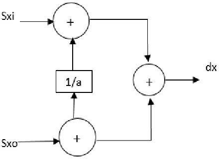
Fig 1. Processing unit of lifting structure
b. Overview of flipping structure for lifting DWT
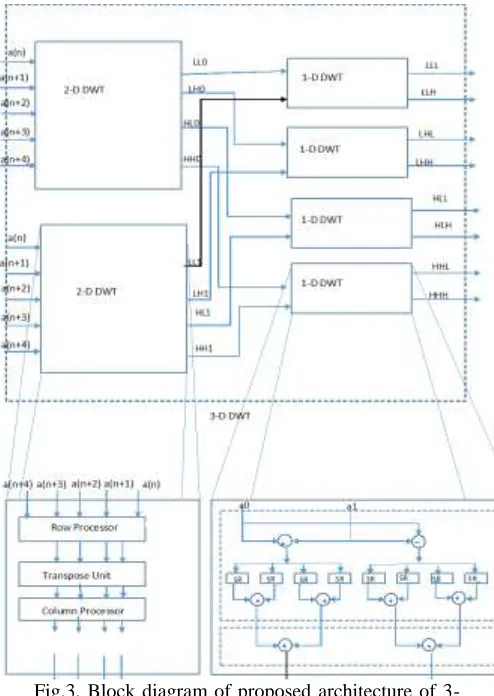
The proposed architecture for 3-D lifting DWT consist of two parallel spatial processors (2-D DWT) for image and four temporal processors (1-D DWT) for video input. The spatial processor produces 4 sub-bands, i.e., LL, HL, LH and HH which are given as inputs to the four temporal processors. The output consists of low frequency frame (L-frame) and a high frequency frame (H-frame).
The 3D DWT structure consists of two types of structure is: combinational component and memory component. The combinational component consists of arithmetic circuits. The memory component consists of a spatial memory (S MEM), temporal memory (T MEM), row (R MEM) and column (CMEM) memory. The below figure 2 illustrates the generic structure of 3D DWT.
Fig.2. Generic structure of 3D-DWT
a) Row Processor (RP):
The proposed parallel pipelining method as shown in fig. 3. It allows the coefficients of alternate rows to be scanned for computing the lifting coefficient by the row processor at each clock cycle as discussed in [1] [17]. Therefore, two registers are used to keep the intermediate data in alternate rows, and the switches are utilized to select those intermediate data. Two sum register and two temporal register are designed to store the data for odd and even row in the row processor, respectively.
b) Column Processor (CP):
The output of the row processor is given to the Column Processor (CP). Two processing unit as shown in fig.1 is designed as column processor. The transpose register gives a pair of H and L coefficients in an alternative order, that are fed to the inputs of one PU of the CP. By using separability property the results are used by the next PE after two clock cycles. The shift registers of length two are
inserted within the column Process between each pair of pipeline. the output of the Column Process gives four sub bands in an interleaved manner.
c)Spatial/Temporal processor
Spatial processor (SP) consists of row and column processors. To implement pipelining in the given equations [8-12] The proposed row processor and column processor have utilized the flipping structure as illustrated in [13].
can be extended to P = 4, 8, 16 or 32 for varying frames.
Fig.3. Block diagram of proposed architecture of 3-D 3-DWT
III. RESULTS AND PEFORMANCE COMPARISON
a. Simulation and Synthesis Results:
The proposed 3-D DWT architecture has been coded in Verilog HDL. A uniform word length of 15 bits for the given image coefficients is used. Simulation is verified by using test bench for the given image input coefficients. The stimulation is done using Matlab for loading and retrieving the image coefficients. RTL simulation using Model Sim have been done to exactly match the MATLAB simulation. The input taken from the system is given in binary coefficients are loaded in Verilog file and the sample input is shown in figure. 4. After performing lifting steps the corresponding output coefficients are loaded in Verilog file. The given input image of the size N×N, where N=256, frame size is fixed, and
column processing is done using symmetric extension. The proposed architecture initiates the DWT process row wise through the row processor (RP) and then process the column DWT by the column processor (CP). The maximum critical path delay provided by these Process Element(PE) is 2Ta. The outputs corresponding to row, column, spatial processor are stored in respective memory. And those stored outputs are entered for next subsequent columns of the same row.
Fig.4. Sample input image
Fig. 5. Sample output image
And the above fig. 4. illustrates an input image for 3D-DWT process of size 256×256 coefficients for this designed architecture. Whenever the row processor produces the intermediate results, the column processor starts to work on those intermediate results to obtained 2-D DWT. Row- column processor takes 10 clocks to give the 2-D DWT output. The temporal processor takes 2 more clock cycle to produce 3-D DWT output. The proposed 2-D DWT and 3-D DWT architectures have latency of 10 to 12 clock cycles respectively, irrespective of the image size N and the number of parallel PUs. And thus the output image is viewed on Matlab screen and image obtained is shown in below fig.5.
The table I summarize the device utilization of lifting 3-D DWT, the logic utilization is high which is not a drawback for achieving high speed in real time video application. hence, the table I gives the device utilization summary. It is clear that the utilization of slice registers was very low where else the block RAM was utilized.
Table I Device utilization summary
LOGIC UTILIZED USED AVAILABLE UTILIZATION
Slice registers 3135 126800 2%
Number of slice LUT’s 117806 63400 185%
Number of fully used LUT-FF pairs
1520 119421 1%
Number of Block RAM 128 135 94%
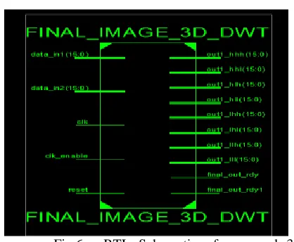
The RTL schematic of the lifting 3-D DWT as shown
in fig.6.
Fig.6. RTL Schematic of proposed 3-D DWT Lifting Architecture.
b. Comparison of the proposed method with existing architecture
Comparison of the proposed architecture with the existing 3D-DWT architecture [18], is shown in the table II. It shows that proposed design possesses the features of less memory requirement, high throughput, less computational time and minimal latency compared to the existing one. It is also noted that the speed of the proposed method is higher than the existing method [18], the maximum operating frequency of the proposed architecture reaches 373 MHZ. The proposed architecture achieves high speed as shown in the table II. It is clear that utilization is less than 100%, with
increase in hardware complexity and achieves a high speed suited for real time multimedia applications.
Table II: Comparison of proposed 3-D DWT architecture with existing works
PARAMETERS DAS [18]
existing work
Proposed work
ASIC/FPGA Xilinx FPGA
xc4vfx140
Xilinx FPGA xc7a100t-3-csg324
Speed 310 MHZ 373 MHZ
Area 1853 slices 1525 slices
Memory requirement 10 (N/2) [10 blocks]
128 blocks
Latency 4N + 28 8 cycles
Multipliers Nil Nil
Adders 26 X 3 162
Filter bank 9/7 9/7 loss DWT
Hardware utilization 100 % 94 %
IV. CONCLUSION
The high speed and hardware efficient architecture for lifting method for 3-D DWT suited for video input frames is discussed in this paper. The architecture is being implemented on xc7a100t-3-csg324 FPGA achieving speed, reduction in latency and better hardware utilization. When compared with several existing architectures, the proposed method gives higher speed performance at the cost of a slight increase in area. This architecture can compute the maximum of fixed frame size of 256 X 256 coefficient of image size. The novelty of this method involves reducing the critical path delay by using only adders for computing the lifting steps. The idea of the proposed 3-D DWT architecture can be extended for video compression and idea be extended for real time video with variable frame size. The reconfigurability of device can be done for better optimization suited for real time multimedia applications.
References
[2] Wei Zhang, Member, IEEE, Zhe Jiang, Zhiyu Gao, and Yanyan Liu, “An Efficient VLSI Architecture for Lifting-Based Discrete Wavelet Transform” IEEE TRANSACTIONS ON CIRCUITS AND SYSTEMS—II: EXPRESS BRIEFS, VOL. 59, NO. 3, MARCH 2012
[3] Xin Tian, Lin Wu, Yi-Hua Tan, and Jin-Wen Tian, “Efficient Multi-Input/Multi-Output VLSI Architecture for Two-Dimensional Lifting-Based Discrete Wavelet Transform” IEEE TRANSACTIONS ON COMPUTERS, VOL. 60, NO. 8, AUGUST 2011
[4] Anirban Das, Anindya Hazra, and Swapna Banerjee,” An Efficient Architecture for 3-D Discrete Wavelet Transform” Ieee Transactions On Circuits And Systems For Video Technology, Vol. 20, No. 2, February 2010.
[5] Yeong-Kang Lai, Lien-Fei Chen, “A High-Performance and Memory-Efficient VLSI Architecture with Parallel Scanning Method for 2-D Lifting-Based Discrete Wavelet Transform” IEEE Transactions on Consumer Electronics, Vol. 55, No. 2, MAY 2009.
[6] Tinku Acharya and chaitali chakrabarti, “A Survey on Lifting-based Discrete Wavelet Transform Architectures” Received July 29, 2004; Revised June 14, 2005; Accepted August 4, 2005.
[7] A. Darji, S. Shukla, S. N. Merchant and A. N. Chandorkar, “Hardware Efficient VLSI Architecture for 3-D Discrete Wavelet Transform,” Proc. of 27th Int. Conf. on VLSI Design and 13th Int. Conf. on Embedded Systems pp. 348-352, 5-9 Jan. 2014.
[8] Q. Dai, X. Chen, and C. Lin, “Novel VLSI architecture for multidimensional discrete wavelet transform,” IEEE Transactions on Circuits and Systems for Video Technology, vol. 14, no. 8, pp. 1105-1110, Aug. 2004.
[9] Z. Taghavi and S. Kasaei, “A memory efficient algorithm for multidimensional wavelet transform based on lifting,” in Proc. IEEE Int. Conf. Acoust Speech Signal Process. (ICASSP), vol. 6, pp. 401-404, 2003.
[10] M. Weeks and M. A. Bayoumi, “Three-Dimensional Discrete Wavelet Transform Architectures,” IEEE Transactions on Signal Processing, vol. 50, no. 8, pp.2050-2063, Aug. 2002. [11] T.Acharya, C.Chakrabathi, “A survey on lifting based discrete
wavelet transform architecture.” J.VLSI Signal Process.42,321-339(2006)
[12] I.Daubechies W,.Sweldens, Factoring wavelet transform into lifting steps. J. Fourier Anal.Appl. 4,247-269(1998) [13] C.T. Huang ,L.G. Chen, P.C Iseng , Flipping structure: an
efficient VLSI architecture or lifting based discrete wavelet transform, IEEE trans. signal process (2004) 1080-1089 [14] C.T. Huang ,L.G. Chen, P.C Iseng , An efficient VLSI
architecture or lifting based discrete wavelet transform by systematic design method, in International symposiumon circuits and systems, vol. 5(2002)
[15] Charilaos Christopoulos, Athanassios Skodras ,Touradj Ebrahimi The JPEG 2000 still image coding system an overview IEEE Transactions on Consumer Electronics, (2000) Vol. 46, No. 4, pp. 1103-1127
[16] Sayed Ahmad Salehi and Rasoul Amirfattahi, VLSI Architecture of Lifting based Discrete Wavelet Tranfrom (2007)
[17] B.K.N.Srinivasarao and Indrajit Chakrabarti, High Speed VLSI Architecture for 3-D Discrete Wavelet Transform, IEEE trans.(2015).