ISSN: 2231-5381
http://www.internationaljournalssrg.org
Page 471
Implementation of FPGA based PID Controller for
DC Motor Speed Control System
Prashant Kumar#
1, Ravi Mishra*
21#
M.E.(Student), Electronics and Telecommunication Engineering Department SSCET, CSVTU, Bhilai, India
*2
Associate Professor, Electrical & Electronics Engineering Department SSCET, CSVTU, Bhilai, India
Abstract— In this paper, the implementation of
software module using 'VHDL' for Xilinx FPGA (XC2S30) based PID controller for DC motor speed control system is presented. The tools used for building and testing the software modules are Xilinx ISE 9.1i and ModelSim XE III 6.3c. Before verifying the design on FPGA the complete design is simulated using Modelsim Simulation tool. A test bench is written where, the set speed can be changed for the motor. It is observed that the motor speed gradually changes to the set speed and locks to the set speed.
IndexTerms— Field Programmable Gate Array
(FPGA), Proportional-Integral-Derivative (PID)
controller, Very High Speed Integrated Circuit Hardware Description Language (VHDL), Pulse Width Modulation (PWM).
I. INTRODUCTION
Hardware Description Languages (HDLs) are used to describe hardware for the purpose of Simulation, Modeling, Testing, Design, and Documentation of digital systems. The most popular HDLs are VHDL [(Very High Speed Integrated Circuit) Hardware Description Language], and Verilog. VHDL is used to describe hardware from the abstract to the concrete level. Many of the Electronic Design Automation (EDA) vendors are standardizing on VHDL as input and output from their tools. These tools include simulation tools, synthesis tools, layout tools and testing tools.
The Proportional-Integral-Derivative (PID) controllers have been widely used over the past five decades due to their simplicity, robustness, effectiveness and applicability for a broad class of systems. Despite the numerous control design approaches that have appeared in the literature, it is estimated that, now a day’s PID controllers are still employed in more than 95% of industrial processes [1]. For many decades, the digital PID controller has been used extensively in real time digital control. The PID is used extensively in the field of servo motor control, robotics, temperature control and power electronics. It has a long history of development and very mature tuning rules. overall, the PID is an important tool for the embedded real time digital
control designer. They are usually implemented either in hardware using analog components or in software using computer-based systems.
The emergence of field programmable gate arrays and hardware description languages allows for added dimensions of digital PID controllers, Parallelism, Programmable bit widths and absolute determinism. Building PID controllers on Field Programmable Gate Arrays (FPGAs) improves speed, accuracy, power-efficiency, compactness and cost effectiveness.
With the growing complexity of motor and motion control applications, it becomes apparent that a Field Programmable Gate Array (FPGA) offers significant advantage over the off shelf Application Specific Standard Product (ASSP) solutions in the areas of performance, flexibility and inventory control [2]. Custom motor drive interfaces such as Pulse Width Modulation (PWM) can be developed easily, quickly and at low cost. Additionally, because of full configurability, the same FPGA can be used in various product ranges, reducing the need to maintain inventory for multiple devices [3].
The Spartan2 family of Field-Programmable Gate Arrays is specifically designed to meet the needs of high volume, cost-sensitive consumer electronic applications. The six-member family offers densities ranging from 15,000 to two million system gates. Because of their exceptionally low cost, Spartan2 FPGAs are ideally suited to a wide range of consumer electronic applications, including broadband access, home networking, display/projection and digital television equipment. Modern FPGAs and their distinguishable capabilities have been advertised extensively by FPGA vendors [4]. Moreover, some refereed articles addressed the advantages of utilizing these powerful chips [5][6].
ISSN: 2231-5381
http://www.internationaljournalssrg.org
Page 472
chips is old and well known [13][14], whereas verylittle work can be found in the literature on how to implement PID controllers using FPGAs. A PWM generator is introduced in [15]. However, only simulation results are presented. The contributions of the authors in [16][17] are considered complementary to the present work as they provide tools for building the current application. The software developed provides the user interface through on board peripherals like Pushbuttons and Seven Segment Displays, so that the user can change the set speed of the motor as well view the data display on Seven Segment Display. The organization of this paper is given as follows: In section II, an overview of the complete system, In section III, functional modules of a FPGA based PID controller for DC motor speed control system are explained. In section IV, the implementation results of the system are discussed. Conclusions are discussed in section V.
II. OVERVIEW OF COMPLETE SYSTEM
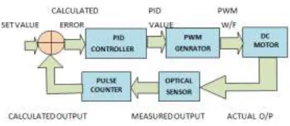
The set speed is assigned to switches according to the requirement and the capture control switch is enabled. Once this is done the generated set value and previous calculated value of speed will be read and sent to the PID controller as an error value. To calculate the current speed optical sensor and pulse counter module is used in the feedback system. The PID controller module will calculate the equivalent PID value and send to the PWM generator module and it is fed to the motor through DAC and once the current speed equals the set speed, the motor starts running at the set speed. Again to change the set speed, the above procedure is repeated by pressing another push button switch.
.
Fig. 1 Block diagram of the complete system
Figure 1 shows the overall view of the system along with the implemented modules on FPGA. As the set speed is varied, the PWM waveform also varies. It is observed that the current speed, which is displayed, on the seven segment display equals the set speed value. Also the change in the motor speed for different switch can be observed accordingly.
Table 1 shows the set value of the PID controller for the DC motor speed control system for various set speeds.
III. OVERVIEW OF FUNCTIONAL MODULES
The target FPGA device used in the present work is Spartan2 family XC2S30 manufactured by Xilinx. Design development and debugging is carried on a low-cost, FPGA ISP kit. This board provides all the tools required to design and verify Spartan2 platform designs. Designs are based on 8 MHz clock. Figure 2 shows the Hierarchical Diagram of FPGA Based PID Controller Implementation for DC motor speed control system. The software tools used for building and testing these modules are Xilinx ISE 9.1i and ModelSim XE III 6.3c.
Fig. 2 Hierarchical Diagram of FPGA Based PID Controller
A. Combine_hardware module
The Combine_hardware Top module is the Main Top level VHDL module in the hierarchy. It instantiates the combine– pid sub module. It interconnects all the
signals and interacts with the external world.
The top module, combine-hardware module
provides the user interface where user can give the desired set speed for the DC Motor. It instantiates the Combine-PID sub module. It interconnects all the
signals and interacts with the external world. Here four push button switches, s1, s2, s3 & s4 are used to get the set speed of 1000 rpm, 800 rpm, 600 rpm, & 200 rpm respectively. Same switches can also be assigned to get the other speed like 400rpm, 300 rpm, & 200 rpm by assigning the different set value to the switches which will be one of the input for the PID Controller.
COMBINE_HARDWARE
COMBINE_PID
MOTOR_IN
PID_XIL
ISSN: 2231-5381
http://www.internationaljournalssrg.org
Page 473
B. PID controller module
Figure 3 shows the Combine-pid sub module having
own sub modules with main internal and external signal flow. The PID Controller Top module is the Main Top level module of combine hardware module in the hierarchy. It instantiates the sub modules motor_in, pid_xil and pwm2 modules. It interconnects all the signals and interacts with the external world.
Fig.3 PID Controller Submodules
1. Motor-in module
The Motor-in module receives the current
speed data (rpm) of motor, which is latched into the module using sensor control signal from the optical sensor. Once the optical sensor data is latched into the module it calculates the current speed, which is sampled to the PID controller as one of the input, after every 4 micro second. This is done to get the calculated digital value for current speed of the DC Motor.
2. Pid-xil module
Once the current speed is calculated, this value is subtracted with the set speed value, which is set using the push button switches connected to s1, s2,s3 & s4, in combine_hadware top module. It has several state machines like Reset, CalculateNewError, CalculatePID, DivideKg, Write2DAC, SOverload and ConvDac. In this module amount of error & proportional, integral and derivative value of the PID
Controller is calculated. After calculation of error & PID value, actual output of the module is calculated, to be sent to the next module pwm2. Calculated output value is written to the dac-data port. The value
of constants Kp, Ki and Kd are initialized for motor application.
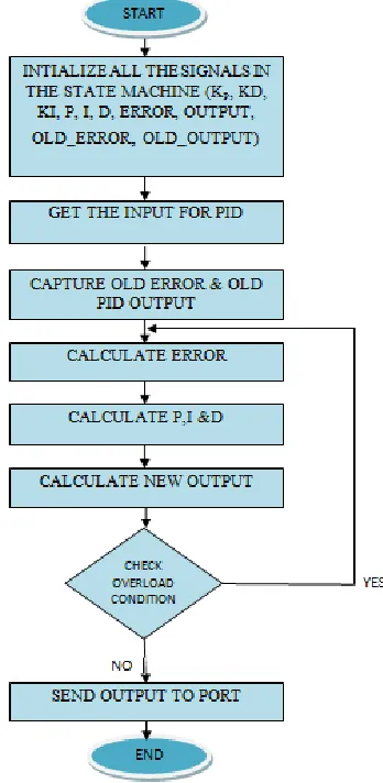
STATE FLOW DIAGRAM
The state flow diagrams are so drawn that, they are self explanatory and gives the complete idea of software development for FPGA based PID controller for DC motor speed control system. Figure 4 shows State flow diagram for PID controller
ISSN: 2231-5381
http://www.internationaljournalssrg.org
Page 474
3. Pwm2 moduleThe last sub module of the combine-pid module
communicates with the pid-xil module using dac-data
signal. Here two independent increment & decrement counters are used to generate the PWM waveform. Both the counter decides either low logic level or high logic level for the PWM output waveform. The output value of the pid-xil module is the input value
for these counters.
The output pwm value generated by the module is converted to the equivalent analog value to be sent to the DC motor.
IV. RESULTS
A. Simulation Results
Logic simulation in FPGA design environment plays a very vital role in verifying the functionality of the designs. Simulation is a powerful way to test the system on a computer, before it is turned into hardware. Simulators let designer to check the values of signals inside the system.
In the present study, for functional verification, before verifying the performance of proposed controller design on FPGA, the complete design is simulated using Modelsim Simulation tool (Xilinx version ModelSim XE III 6.3c), which has pre-compiled libraries for all Xilinx FPGAs. A test bench is written where, the set speed can be changed for the
motor. In the test bench, the Top module of the design combine-hardware is instantiated. The inputs
like Clock, Reset, Switch data and sensor are defined and the output [motor-run, speed on seven segment
display {d1, d2, d3 & d4}] is observed in the simulation window.
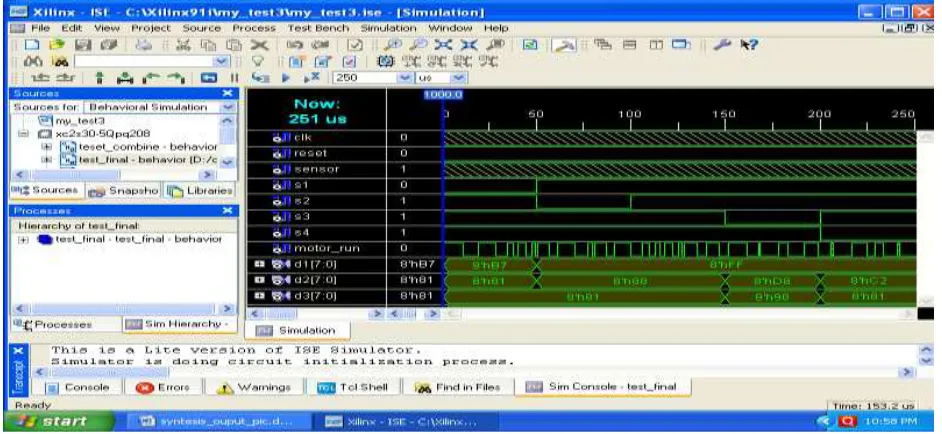
As many sub modules are instantiated in Top module and as this is a hierarchical design, internal sub module signals are also observed in the waveform window of the simulator. Once all the signals are taken into the waveform window, the simulation is run for 250 us (is and the changes in the signals are observed in the waveform window. It is observed that the motor speed gradually changes to the set speed and locks to the set speed.
Figure 5 shows the simulation results for the set speed of 1000, 800, 600 & 200 rpm. It is seen that after certain transitions, when the error value is calculated, the current speed becomes equals to set speed. When the optimal values for Kp, Ki and Kd are used to calculate the current speed, the current speed will equal the set speed when error become zero, hence motor starts running at the set speed.
Figure 6 shows the Design Summary, Xilinx tool device utilization summary and reports the percentage of available resources that have been used for the current FPGA design. The performance summary summarizes the timing requirement and also the proper routing of the signals.
ISSN: 2231-5381
http://www.internationaljournalssrg.org
Page 475
B. Hardware Test Results
The experimental studies are carried out to evaluate the performance of the controller. Configuration is the Process by which the bit streams of a design, as generated by the development software are loaded into the internal configuration memory of the FPGA. To verify the performance of the controller design on Hardware, the VHDL code (Bit file) is downloaded into the Target FPGA device (Spartan2 family XC2S30) and the complete system is reset. The set speed is assigned to switches s1,s2,s3 & s4 according to the requirement and the capture control switch is enabled. Once this is done the ADC data will be read and PID equation implemented will calculate the equivalent PID value and it is fed back to the motor through DAC and once the current speed
Fig. 6 Experimental setup of FPGA based PID controller for DC motor speed control.
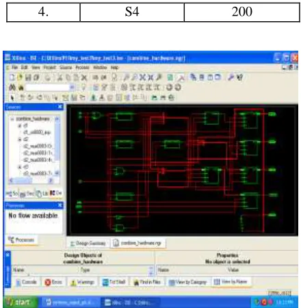
equals the set speed, the motor starts running at the set speed. Again to change the set speed, the above procedure is repeated by changing the push button switch position. Figure 6 shows the experimental setup for DC motor speed control system. Fig 7 shows RTL View of module Combine-hardware.
Table 1 Push button switches for given set speed.
Sl.No Push button
Switch Set Speed (rpm)
1. S1 1000
2. S2 800
3. S3 600
4. S4 200
Fig. 7 RTL View of module Combine-hardware
As the set speed is varied, the ADC voltage also varies. It is observed that the current speed, which is displayed, on the seven segment display is equal to the set speed value. Also the change in the motor speed for different switch combinations can be observed accordingly. Table 1 shows the results of the DC motor speed control system for various set speeds.
v. Conclusions
ISSN: 2231-5381
http://www.internationaljournalssrg.org
Page 476
compactness and cost effectiveness over other digital implementation techniques.References
[1] K.J. Astrom and T. H. Hagglund, “New Tuning Methods for PID Controllers,” Proc. of 3rd European Conference, pp. 2456-2462, 1995.
[2] Shouling He and Xuping Xu, “Hardware/Software Co design Approach for an ADALINE Based Adaptive Control System,”
Journal of Computers, vol. 3, no. 2, pp. 29-36, Academy publisher, February 2008.
[3] Craig Hackney, “PGA Motor Control Reference Design,” Application Note: Spartan and Virtex FPGA Families, Xilinx XAPP808 vol. 1.0, September 16, 2005.
[4] Mohamed Abdelati, “FPGA-Based PID Controller Implementation,” The Islamic University of Gaza, Palestine, This research was supported by the Ministry of Higher Education in Palestine.
[5] Anthony Cataldo, “Low-priced FPGA options set to expand,” Electronic Engineering Times Journal,
no. 1361, pp. 38-45, USA, 2005.
[6] Gordon Hands, “Optimised FPGAs vs dedicated DSPs,” Electronic Product Design Journal, vol. 25, no. 12, UK, December 2004.
[7] R. Jastrzebski, A. Napieralski, O. Pyrhonen and H. Saren, “Implementation and simulation of fast inverter control algorithms with the use of FPGA circuit,” Nanotechnology Conference and Trade Show, pp. 238-241, Nanotech 2003.
[8] Lin. F.S, Chen. J.F, Liang. T.J, Lin. R.L and Kuo, Y.C, “Design and implementationof FPGA-based single stage photovoltaic energy conversion system,”
Proceedings of IEEE Asia-Pacific Conference on Circuits and Systems, pp 745-748, Taiwan, December 2004.
[9] Bouzid Aliane and Aladin Sabanovic, “Design and implementation of digital bandpass FIR filter in FPGA,” Computers in EducationJournal, vol.14, pp. 76-81, 2004.
[10] M. Canet, F. Vicedo, V. Almenar and J. Valls, “FPGA implementation of an IF transceiver for OFDM-based WLAN,” IEEEWorkshop on Signal Processing Systems, SiPS: Design and
Implementation , pp. 227-232, USA, 2004.
[11] Xizhi Li and Tiecai Li, “ECOMIPS: An economic MIPS CPU design on FPGA,”
Proceedings- 4th IEEE International Workshop on System-on-Chip for Real-Time Applications, pp. 291-294, Canada 2004.
[12] R. Gao, D. Xu and J. P. Bentley, “Reconfigurable hardware implementation of an improved parallel architecture for MPEG-4
motion estimation in mobile applications,” IEEE Transactions on Consumer Electronics, vol.49, no.4, November 2003.
[13] H. D. Maheshappa, R. D. Samuel and A. Prakashan, “Digital PID controller for speed control of DC motors, IEEE Technical Review Journal, vol. 6, no.3, pp. 171-176, India, 1989.
[14] J. Tang, “PID controller using the TMS320C31 DSK with on-line parameter adjustment for real-time DC motor speed and position control,” IEEE International Symposium on Industrial Electronics, vol. 2, pp. 786-791, Pusan, 2001.
[15] D. Deng, S. Chen and G. Joos, “FPGA implementation of PWM pattern generators,”
Canadian Conference on Electrical and Computer Engineering, and Electronics Engineers Inc, vol. 1, pp. 225-230 May, 2001.
[16] Rivera. D.E, S. Skogestad and M. Morari, “Internal Model Control 4. PID Controller Design.” Ind. Ene Chem. Proc. Des & Dev, 25, pp. 252.265, 1986.