50 | P a g e
STATIC STRUCTURAL ANALYSIS OF 3 AXIS CNC
MACHINE TABLE USING FINITE ELEMENT
ANALYSIS
Parag R. Bhingardeve
1, Rajani T. More
2, Sujit S. Malgave
3 1,2Student, Department of Mechanical Engineering, AITRC, Vita, (India)
2Assistant professor, Department of Mechanical Engineering, AITRC, Vita,(India)
ABSRACT
A machine table is the component which holds and supports the work piece. To obtain a good finished and
accurate work piece on a 3 axis CNC machine, a table should be sufficient rigid and must have good
mechanical properties. A finite element analysis gives a systematic study of failure criterion which helps for
further development of the 3 axis machine tables. In this paper, Static Analysis is performed on machine table to
find out stresses generated in table, deformation of the table due to its weight. The finite element analysis is
performed by making 3D geometry in CATIA software and analyse by using ANSYS software.
Keywords: Cast Iron, Deformation, FEM, Machine Table, Static Structural
I. INTRODUCTION
3 axis CNC machine table is the rectangular casting located on the base which supports the fixtures & the work
piece while machining. The table rest on ways on the saddle. The top of the table is accurately finished and T-
slots are provided for clamping the work and other fixtures on it. The table fixed on machine structure receives
vertical forces of work piece and fixtures.
51 | P a g e
In the past few decades, the finite Element Analysis (FEM) has been developed for the modelling andsimulation of various engineering systems. The basic idea in the FEM is to find out the solution of complicated
problems with relatively easy way. Finite element method is a numerical method used to solve physical
problems governed by a differential equation. In the Finite Element Method, the solution generated by analysing
many small sub regions called Finite elements.
The C. C. Hong et al. [1] worked on great five axis turning-milling complex CNC machine. The paper provides
information of computer aided engineering (CAE) for industries. They have performed analysis on secondary
and primary shaft system, machinery bed with respect to static construction, stresses & deformation. By using
various boundary conditions they found out maximum displacement values for machinery bed and they state
that the external load value below 10Mpa is safe for machinery bed. Also they got the results for reducing
weight of CNC machine and maintain good stress to resist external load.
The B. Malleswara et.al [2] presents their paper on modelling and analysis of milling machine bed for reducing
weight of machine bed by its dynamic and static analysis. They made modelling of machine bed in CATIA and
after analyse by using ANSYS with boundary conditions. They take three material grades of cast iron G15, G40
and G70. They conclude that the G 15 material is better due to its mechanical and vibrational characteristics.
The B. V. Subrahmanyam et al. [3] have performed static and dynamic analysis on three types of machine
structure i.e. milling machine, shaping machine, lathe machine. In ANSYS they fixed the base of machine and
the load on machine is considered as machine’s self-weight. They conclude that the stresses generated in lathe
machine structure is more than other two, also they conclude that as the natural frequencies increases the
deformation gets increases.
The Sujeet Ganesh Kore et al. [4] worked on use of bionic structure in machine tool design. The main aim the
study is to optimization of machine structure using bionic structure design. In the paper they analyse two types
of structures i.e. existing bed model and optimized bed model by using CI and structural steel as a material.
They succeed to make an optimized model which has low weight and good mechanical properties.
The B. Li et al. [5] worked for optimization machine tool bed with weight distribution consideration. In this
paper they took the bed structure of grinding machine for optimization. They prepared the spring model of the
bed which consists of stiffener plates for analysis purpose. From this study they conclude that the method of
finite element analysis can be easily employed to find load bearing topology for reduction of the weight of
machine bed.
The auther S. D. Kamble et al. [6] have made their paper on the frame analysis of EDM machine tool. They
assembled the machine using 3D modelling software CATIA and analysis is done by using ANSYS. In this
paper they take four channel thicknesses designs having thickness 6mm, 5mm, 4mm, 3 mm. After analysing
they found that the maximum stress is acts at centre of machine table, the 5 mm channel thickness design have
52 | P a g e
II. METHODOLOGY
The methodology is subdivided into three parts
CAD model
Defining materials
Static Analysis
2.1 CAD Model
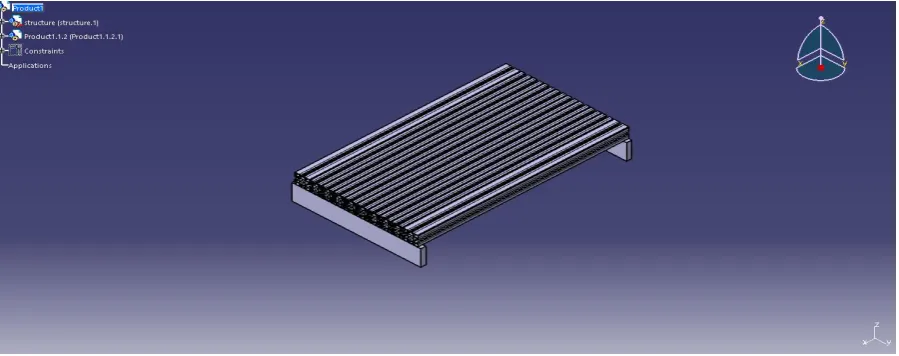
For the analysis of the machine table, firstly the CAD model of the table is created by using CATIA V5
software. The dimensions which are taken for the table are given below.
Fig. 2.1 Dimensions of CNC Machine Table
The 3D modelling of machine table is done by using Part Design and Assembly Design workbenches.
The modelled machine table by using CATIA V5 is shown in Fig. 2.2.
53 | P a g e
2.2 Materials and its properties
The material used for the machine table is grey cast iron. In this paper, for the analysis purpose three materials
are used i.e. ASTM grade 20 (ISO grade 150, JL 1020) grey cast iron, ASTM grade 30 (ISO grade 200,
EN-JL 1030) grey cast iron and ASTM grade 50 (ISO grade 350, EN-EN-JL 1060) grey cast iron. The properties of the
above grades are given in below table.
Table No. 2.1 Properties of grey cast iron grade
Material Properties Grade 20 Grade 30 Grade 50
Density 7.2 g/cm3 7.2 g/cm3 7.2g/cm3
Young’s Modulus 82 Gpa 100 Gpa 140 Gpa
Poisson’s Ratio 0.26 0.26 0.26
Tensile strength: Ultimate 150 Mpa 220 Mpa 380 Mpa
Compressive Strength:
Ultimate 570 Mpa 750 Mpa 1130 Mpa
2.3 Static Analysis
A static analysis gives a result when the forces acting on structure at rest position. From the static analysis we
can find out deformations of the structure, stresses generated in the structures and failure modes of the machines
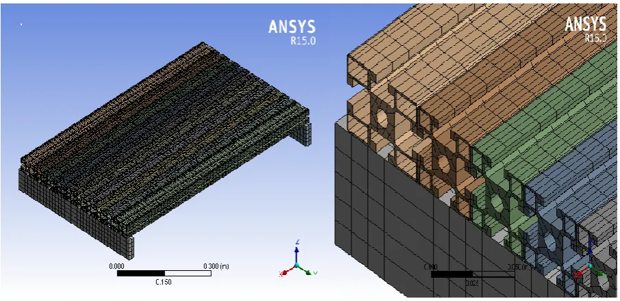
at rest condition. For the analysis, Mesh generation is an important phenomenon. After the importing the CAD
model in ANSYS the important step is to mesh that model. For 3 axis CNC machine table the mesh is generated
with fine relevance centre by using mesh tab. After solving the meshing process the total elements generated is
60664 and the number of nodes is 351522.
54 | P a g e
The boundary conditions used for all three grades are, the legs of the machine table if fixed i.e. the all degrees offreedom of the legs are becomes zero. The load acting on the machine table is its self-weight which is generated
by standard earth gravity.
Fig. 2.4 Boundary conditions for static analysis
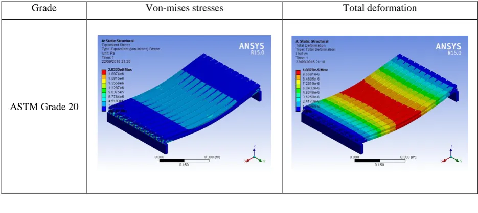
Using above boundary conditions, the equivalent stress (von-mises stresses) and total deformation is found out
for every grade of cast iron. The results find out by using static structural analysis is given in below table.
Table No. 2.1 Von-mises stress, Total Deformation of table
Grade Von-mises stresses Total deformation
55 | P a g e
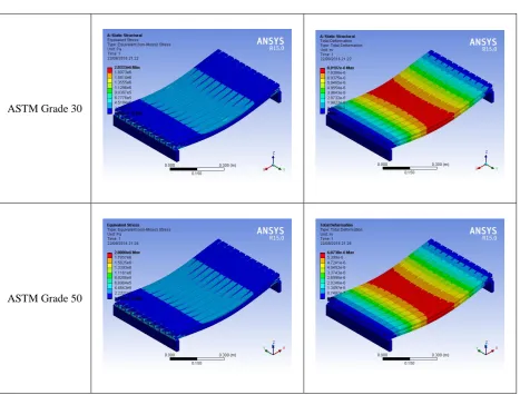
ASTM Grade 30ASTM Grade 50
III. RESULTS AND DISCUSSIONS
The results show that the maximum deformation due to self-weight is at centre of the table. The deformation of
grade 50 material is less than other two grades. The results are compared in tabular data for the three grades of
cast ironare given below.
Table No. 3.1 Static analysis results
Vonmises Stress Total Deformation
G 20 2.0333MPa 0.010878mm
G 30 2.0333MPa 0.0089197mm
G 50 2.0089MPa 0.0060738mm
IV. CONCLUSION
From this paper we conclude that the deformation of Grade 50 material is 44.16% less than Grade 20 and
56 | P a g e
materials. From these results it is observed that the Grade 50 material is best suited for the machine table instatic loading because of its material properties and less deformation.
REFERENCES
[1] C.C. Hong, Cheng-Long Chang, Chien-Yu Lin, Static structural analysis of great five-axis turning–milling
complex CNC machine, ELSEVIER, 2016, 1-14
[2] B. Malleswara Swami, K.Sunil Ratna Kumar, Design and Structural Analysis of CNC Vertical Milling
Machine Bed, International Journal of Advance Engineering Technology, Vol. 3, Issue IV, 2012, 97-100
[3] B.V. Subrahmanyam, A. Shrinivasa Rao, S.V. Gopala Krishna, CH. Rama Krishna, Static and Dynamic
analysis of machine Tool structures, International journal of Research in Mechanical Engineering &
Technology, Vol. 4, Issue Spl-1, 2013- 2014, 14-18
[4] Sujeet Ganesh Kore, M I Sakri, L N Karadi, Design and Analysis of a Machine tool Structure Based on
Structure Based on Structural Bionics, International journal of Mechanical Engineering and Robotics
Research, Vol. 3, 2014, 731-737
[5] B. Lia, J. Hong, Z. Wang, W. Wu, Y. Chen, Optimal Design of Machine Tool Bed by Load Bearing
Topology Identification with Weight Distribution Criterion, ELSEVIER, 2012, 621-631
[6] S. D. Kamble, A. S. Todkar, Structural Analysis for Frame of a Machine Tool-EDM Using CAE tools
through the Evaluation Phase of the Design, International Journal of Advance Engineering Technology,