180 | P a g e
VOLTAGE SAG AND SWELL COMPENSATION
USING IDVR
Mr. Nagesh Rameshwar Thakre
1, Prof. Rajendra H.Madhavi
21
Mtech Student,
2Assistant Professor, Department of Electrical Engineering,
Dr. Babasaheb Ambedkar Technological University, Lonere, Raigad, Maharashtra, (India)
ABSTRACT
Now days, there is increase in power electronic devices and nonlinear loads which are more sensitive to power
quality. So power quality is more concerned issue from customer side. Most of the power quality problem is
related to the voltage. Such power quality problem causes enough damage and economic losses in
manufacturing process.Mr. N. G. Hingorani has proposed Custom Power Devices (CPD) to overcome such
problems. This paper discusses operational principle of Dynamic Voltage Restorer (DVR) and SVPWM control
techniqueused for VSC in DVR. DVR has limitations to compensate long duration voltage sag. Solution over this
problem is inter-line DVR. Effectiveness and operational result of IDVR can be seen from matlab
Simulinkmodel and its results.
Keywords:
Voltage Sag and Swell, DVR,IDVR, SVPWM,
I. INTRODUCTION
Development in any county is mainly because of the growth in modern industries. Such modern industries
always include innovation in technologies and they come to success only by optimized production to have
maximum profits.Modern industries require stable and uninterrupted power supply to perform efficiently. The
main complains from distribution side related to the voltage quality. Most of the economical and manufacturing
losses in industries are due to voltage sag and swell. Such power quality problems are compensated by using
Custom Power Devices which were introduced in 1990’s.
This paper introduces the Dynamic Voltage Restorer which one is the best CPD to overcome these problems.
Series connected DVR works on basic principle of injection of require amount of voltage in transmission line by
appropriate value of magnitude and phase angle. That injected voltage is taken out from any storing devices like
batteries, flywheels. Efficiency and performance of DVR depends on energy stored in storing device. Such DVR
cannot perform veryefficiently for long duration voltage sag compensation. This paper also introduces interline
connection of DVR and it is called as IDVR.
DVR includes five main parts are as injecting transformer,converter, filter, control circuit and source unit. Space
vector pulse width modulation (SVPWM) technique is used to control the inverting operation. Voltage source
inverter is usedto convert dc voltage to three phase AC voltage. A fault in system iscalculatedusing
181 | P a g e
II. OPERATING PRINCIPLE OF DVR
DVR is connected in series with load and source. Sudden change in large load or other factors can cause quality
problem in system.If system is under voltage sag then there will be lesser magnitude across load as compared to
deserving voltage. DVR needsto inject voltage in system to maintain constant voltage across load.
Sag Injected Voltage
Compensated Voltage
Filter
Converter
Load1 Load2
AC Source
Energy storing Device
Injecting Transformer
Control Unit
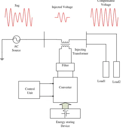
Fig 1. Operating principle of DVR
Operating principle of DVR is as shown in fig 1. As there is voltage sag from source side, the injecting
transformer feeds required amount of voltage from storing device and compensated constant voltage is delivered
to the load [6].
III. BASIC CONFIGURATION OF DVR
Basically DVR requires five main components for proper operation. These are as fallows.
1. Injecting Transformer
2. Energy Storing Device
3. Voltage Source Converter
4. Filter
5. Control Unit
All above components are shown in fig 1 and discussed ahead briefly [6].
1. Injecting Transformer
Injecting transformer is used to inject require amount of voltage in magnitude and phase shift. It is used in series
with distribution feeder. We can use any one of three phase transformer or three single phase transformer.
182 | P a g e
It is used to supply real amount of power in system. Performance of DVR mostly depends on the stored energy
in device. It supplies the required amount of voltage to the converter. Energy storing device could be any of
batteries, PV cell, Fly wheel etc.
3. Voltage Source Converter
Input of the converter is connected to DC batteries. Inverter is required to convert DC to AC and this converter
is of two types, one is voltage source and other one is current source based.Different control techniques have
been used for switching operation of inverter.
4. Filter
It filters out the higher harmonics components. We can connect filter either load side or inverter side of injecting
transformer. Inverter side filter eliminates higher order harmonics but there might be voltage drop and phase
shift in inverteroutput side. Load side filter avoids above problems but this position injects higher order current
in secondary side.
5. Control Unit
Efficiency of DVR depends on control technique used for inverter. Pulses are generated and these pulses are
used for the switching of the inverter. In this paperSVPWM control technique is introduced to generate pulses.
DVR operates only when there are differences inload voltage and referencevoltage, that difference is measured
by PID controller.
IV. INTER LINE DYNAMIC VOLTAGE RESTORER
Most of the loads and commercials areas are supplied by two or more feeder. Any abnormalities in feeder can
causes problem in quality of supply to the load. This problem would be eliminated by transferring the required
amount of power from another feeder. Static transfer switches has been used for this purpose but it is not
possible to alleviate all power quality problems.
To maintain reliability over voltage sag and swell problems, DVR is installed for each feeder and these
DVRsare connected to a common DC link. This arrangement of DVRs with common DC supply source is called
as Inter line Dynamic Voltage Restorer (IDVR). In IDVR structure, required amount of real power can be feed
easily from another healthy feeder but it has own limitation due to operational characteristics. Capabilities of
DVR for compensating long duration voltage sag depends on the amount of energy stored in dc link [3]. IDVR
has been proposed in many studies to replenish dc link. Mostly two feeders do not cause same problem at an
instant. DVR 1 is connected to feeder 1 and another one is connected to feeder 2. In general when feeder 1 goes
under long duration voltage sag then DVR 1 takes real power dc link and injects required voltage to feeder 1. At
the same time another feeder 2 feeds real power to replenish common dc link [8]. Here we have simulated two
feeders; each one is connected with a DVR. Feeder 1 and feeder 2 cause voltage sag and swell power quality
183 | P a g e
Line Impedance AC
SOURCE
LOAD 1 LOAD 2
INJECTING TRANSFORMER
Line Impedance
LOAD 1 LOAD 2
FILTER
CONVERTER
FILTER CONVERTER
Injecting transformer Common DC
Source
AC Source
Feedre 1
Feedre 2
Fig 2. Block Diagram of IDVR
V. CONTROL TECHNIQUE USED FOR CONVERTER
Three phase voltage source inverter has wide application in control and power system. Operational characteristic
of any inverter is always a switching technique used for it. PWM technique has been famous trade used to
control switching operation. Here we have introduced Space Vector Pulse Width Modulation technique to
control inverter. Rotating flux in ac machine is taken as avoltage vector which is combination of three phase
supply voltage [1].
Followings are the three phase voltage
Combinations of all above three vectors are represented in single rotating vector. Magnitude and phase angle of
that space vector is calculated by Clark’s transformation [1]. Space vector is represented in complex plane as
shown in fig 3.
= e
j2ᴫ/3|V| = [Vα +Vβ]
½184 | P a g e
sector1 sector2
sector3
sector4
sector5
sector6 [100] [110]
[010]
[011]
[001] [101]
V
V1 V2
V3
V4
V5 V6
[000]
[111] ϴ
Fig3. Representation of rotating vector in complex plane
Switching time period can be calculated as fallows.
ϴ
V1, T1 V2, T2
T0
V
Fig4. Representation of T for sector 1
Tz |V| {sin (nᴫ/3- )}
T2 =
Tz |V| {sin (
)}
T0 = Tz- (T1+T2)
Where n= 1 to 6 for any sector
0 ≤ ≤ 60
VI. SIMULATION RESULTS
This paper introduced two feeders connected through DVR to a common DC link.This system model is called as
IDVR and simulated in MATLAB software. Simulation model is shown in fig 5. DVR 1 compensates voltage
sag and another DVR is used to compensate swell quality problem for duration in between 0.3 to 0.8. Simulation
185 | P a g e
Fig 5. Simulation model for IDVR in Matlab
Fig 6.1 simulation results for feeder1 (voltage sag)
186 | P a g e
Feeder 1 Feeder 2
Main supply
voltage rmsph-ph
33kv 66kv
Line Impedance 4 Ω ; 110Mh 4 Ω ; 110mH
Common DC Bus
Voltage
35000 35000
Filter Inductance
and capacitance
2 Ω ; 10 mH ; 0.0177 μF
3 Ω ; 10mH ;
0.0177 μF
Load resistance
and inductance
500 Ω ; 0.8 H 500 Ω ; 0.8H
Supply frequency 50 Hz 50 Hz
Series transformer
turns ratio
1:1 1:1
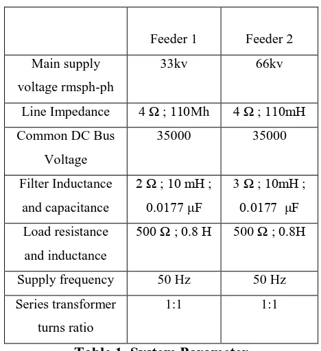
Table 1. System Parameter
VII. CONCLUSION
DVR is suitable device to compensate power quality voltage sag, swell problems. DVR has limitation for long
duration sag compensation. Introduced system model of IDVR is efficient and performed well to mitigate
voltage sag and swell. SVPWM control strategy is used for voltage source converter. SVPWM is easy and
famous technique.
REFERANCE
[1] D. Rathnakumar, J. Lakshmana and T. Shrinivasan ―A New Software Implementation of Space Vector
PWM‖0-7803-8865-08/05/$20.00©2005 IEEE.
[2] M. H. J. Bollen,(2000) ―Understanding Power Quality Problems—Voltage Sags and Interruptions‖
Piscataway, New York: IEEE Press
[3] G.Justin Sunil Dhas, Dr.T. Ruben Deva Prakash ―A Novel approach for Voltage Sag Mitigation Using
FACTS Device Interline Dynamic Voltage Restorer‖ 978-1-4244-8679-3/11/$26.00 ©2011 IEEE
[4]. Ewald F.F, Mohammad A.S.M, (2008), Power Quality in Power Systems and Electrical Machines,
Burlington,USA, Elsevier Academic Press
[5] Rosli Omar, N.A Rahim ―Implementation and Control of a Dynamic Voltage Restorer Using Space
Vector Pulse Width Modulation (SVPWM) for Voltage Sag Mitigation‖
[6] SwapnaliHazarika, SwagataSingha Roy, ―Application of Dynamic Voltage Restorer in Electrical
Distribution System for Voltage Sag Compensation‖ The International Journal Of Engineering
187 | P a g e
[7] AvinashMaurya , K.G.Upadhyay ―Mitigation of short term voltage variations using PV based dynamic
voltage restorer‖ IJSRD - International Journal for Scientific Research & Development| Vol. 2, Issue 06 ,
2014 2321-0613
[8] D. MahindaVilthagamuwa, H. M. Wajekoon, S. S. Choi ―A Novel Technique to Compensate Voltage sag
in Multiline Distribution System- The Interline Dynamic Voltage Restorer‖. IEEE Transaction on