253 | P a g e
ADAPTIVE TRAFFIC LIGHT CONTROL SYSTEM
Ms. Rashmi S. Joshi
1, Mr.Rajanand A.Lonkar
2, Mr. Abhinandan S. Patil
31,2, 3(B.E. VIII semester, Electronics Engineering, D.K.T.E. college, Shivaji University)
ABSTRACT
Our objective is to define a basic scenario in order to understand various problems faced by traditional traffic
light control system and to provide technical solution to amend these adversities to improve the speed of
transport. Congestion due to vehicular traffic intersection at junction is one the major issues to be considered.
To overcome such issues an intelligent traffic signal network is required. Adaptive traffic light control (ATLC)
system deals with manipulation of the green light timings according to the number of vehicles present at each
entry. Our system consists of ARM Cortex based KL25Z controllers, Laser Sensors and Xbee
transmitters-receivers. The supporting program of our system is compiled in ‘mbed portal’ and the simulation is carried out with the help of ‘Proteus’ application. Our system ensures the effective use of allocated delays to deal with these
adversities.
Keywords: ATLC system, KL25Z controller, Xbee, traffic light
I.
INTRODUCTION
Traffic congestion is one of the major problems the world is facing today. Traffic monitoring and controlling is
a difficult task. The aim of the traffic research is to optimize the flow of vehicular traffic and goods. With the
ever increasing vehicles on the road and the number of road users, the limited resources provided by current
infrastructure lead to ever increasing travelling times. Hence, an intelligent control of traffic is an important
factor to be considered. The Traffic Monitoring Authority needs to find new methods for development of
sophisticated traffic monitoring and control systems. One way to improve the traffic flow and safety of the
current transportation system is to apply automation, intelligent and adaptive signal control methods.
There are several models for traffic simulation. With our studies, we have developed a cost effective system
named „Adaptive Traffic Light Control (ATLC) System‟ which consists of the ARM Cortex based KL25Z,
Laser Sensors, Xbee transmitters and receivers. Our main objective is to design a system in order to control the
parameters of a traffic signal, according to the density of vehicles at the square, in terms of congestion and
energy efficiency.
II.
PROBLEM
STATEMENT
Traffic congestion is one of the major problems, the world is facing now-a-days. Traffic monitoring and
controlling is a difficult task. These traffic congestions are often observed at traffic signals.As the vehicle
population is accruing endlessly and the resources providedby current infrastructures are limited,
intelligentcontrol of traffic is an important requirement henceforth.In India, we can observe that the time
254 | P a g e
is an important cause behind such traffic issues. As a result thewaiting time at a signal is increased, which is oneof the reasons behindadditional consumption of fuel and emission of toxic gases ultimately contribute in global
warming.
Fig.1 Traffic congestion
Through this concept we are trying to solve such traffic congestion problems at squares. To make this possible,
we have developed an adaptive algorithm to manipulate delays of a traffic signal.
III.
SYSTEM
INFORMATION
A. Functional Block Diagram
Fig.2 Overview of Traffic Signal at square
Our system is designed to work for traffic signal at the square as shown in fig.2. N1, N2, N3 and N4 are the four
nodes of transmitter sections. Receiver section is either located at control unit of operator or near the signal
driving system. This is connected with the signal driving system which manipulates the signals S1, S2, S3 and
S4.
B. System Block Diagram
The system we are designing is completely dedicated to vary the green light timings according to the density of
vehicles. The system has two basic modules, a transmitter section and a receiver section as shown in figure 3
and figure 4 respectively. For the square, there are four transmitter sections (slaves). Each of them consistLaser
sensors and ARM KL25Z controller which are mounted on the poles at some respective height from the
ground/roads. These Laser sensors are so mounted that every single vehicle passing on the road will cut the laser
individually. The transmitter section is so designed that it counts the number of each kind of vehicles distinctly.
The collected count is transmitted to the master over Xbee network. N3
N4
N1
N2 S1
255 | P a g e
The receiver section consist the same ARM KL25Z controller which acts as a master. A Xbee receiver isinterfaced with the master. The master is connected with the signal driving network system to manipulate the
traffic light delays. This receiver section (master) is situated at the center of the square while the transmitter
sections (slaves) are mountedon respective poles, located at each lane that are about 100 to 200 m away from the
square.
ARM CORTEX BASED
KL25Z Power Supply
Laser Sensor
Xbee Transmitter Transmitter Section
Fig.3 Transmitter section of ATLC system
.
ARM CORTEX BASED
KL25Z Power Supply
Dispaly
Signal Driving system Receiver Section
Xbee Receiver
Fig.4 Receiver section of ATLC system
C. Working:
The ATLC system will work in two modes as,
a. Adaptive mode b. Traditional mode
a) Adaptive Mode:Every vehicle approaching the square has to pass through the sensing network. Thesensing
network consists of various laser sensors mounted at such positions that all the vehicles passing through the
sensing network cut the lasers. Whenever a vehicle cuts the laser beam, the controller at transmitter section
increases the count of vehicles. This action will be carried out simultaneously at four signal entries. This data
from all four entries will be sent to a main ARM cortex controller with the help of respective Xbee transmitters
at each node. A Xbee receiver which is interfaced with master receives the data and transfers to the master for
further process. Based on different vehicles counts, the master takes the decision and manipulates with the
traffic light delays. The transmitter section is situated at a certain distance from the main receiver section so that
we can easily calculate the big number of vehicles passing through the laser network.
b) Traditional Mode:In the traditional mode, the traffic signal will work with fixed allocated green light timing.
When there will be any failure in the coordination in the adaptive mode, the system automatically switches to
256 | P a g e
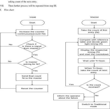
D. Algorithm:I. Total counts from sensors are stored in the respective transmitter sections (slaves).
II. The master controller broadcasts a signal to all the slaves to ask the count of respective entry.
III. When the particular slave acknowledges the signal, it will transmit its count over Xbee network.
IV. Once the master receives the count, it compares that count with the reference table to find required
allocated green light time.
V. When the green light time is finalized, the master will pass that time to the signal driving network,
which controls delays of the traffic signals.
VI. When the last five seconds of that green light time remains, the master again broadcast a signal for
asking count of the next entry.
VII. Then further process will be repeated from step III.
E. Flow chart:
Start
Increase the counter continuously(count=Ni)
Send final count Ni to the master
Is master asking for Ni?
Check if is there a signal
from master?
Reset the counter Yes
Yes No
No
Start
Take the count of first entry (Ni)
Compare with reference table and decide green
light timing (Ti)
Display the respective timing (Ti)
and start the countdown
Wait until Ti=5sec
When Ti=5sec, take the count of next
entry
Is the count received?
Inform the operator about the failure
Switch to Traditional mode
Yes
No
Slave Master
F. Reference Table:
It has predefined values of the delays for different counts of vehicles. It is prepared from the detailed study of a
257 | P a g e
affect on the reference table are location, vehicle population, vehicle kinds and width of the road. The values ofthe reference table are highly dependent on these factors.
For a standard square signal situated at a frequently used location with four lanes each measures hundred feet
with average number of vehicles, the reference table will be as shown:
Number of vehicles (Count) Allocated Green light time
0-5 8 seconds
5-15 12 seconds
15-35 15 seconds
35-50 25 seconds
50 and above 30 seconds
(Note: Considering 60 to 70% bikes, 25 to 30% light & medium duty and 0 to 5% heavy duty vehicles)
IV. COMPONENTS
A. ARM CORTEX BASED KL25Z:
Specifications[5]:
Kinetics L family
32 bit Cortex M0+ processor running up to 48 MHz frequency
128 kb flash and 16 kb SRAM
Available in an 80 LQFP package and having capacitive touch slider
Flexible power supply options – USB, coin cell battery, external source
Fig.5 Block diagram of FRDM KL25Z
B. Laser Sensor:
OptoNCDT ILR 1030/1031 laser distance sensor is preferred. The specifications[6] for the sensors are:
Measuring range up to 15m on diffusereflecting targets / 50m on reflector
Very short response time
C. Xbee Transmitter-receiver:
Xbee-Pro module is chosen because itprovides better results for wireless communication.
258 | P a g e
Range(Indoor/Urban): up to 300‟ (90 m), 200' (60 m) for International variant
Outdoor line-of-sight: up to 1 mile (1600 m), 2500' (750 m) for International variant
Transmit Power: 63mW (18dBm), 10mW (10dBm) for International variant
Receiver Sensitivity: -100 dBm
RF Data Rate: 250,000 bps
V. FUTURE SCOPE
A. This concept can be enhanced if any computer comes inwhole scenario. The camera can be interfaced with
our system at the transmitter section to recognize emergency vehicles. Also it helps the controller to handle
complex data. But on the other hand it will affect on the cost of overall system.
B. With further studies and surveys the adaptive traffic light control system can be designed for more than four
lanes.
C. This system can also be used to inform people about different traffic conditions through RADIO or with
any other media like Internet.
D. If this system is interfaced with GPS network, the communication between vehicle to vehicle can be carried
out. Speed advisory system for the vehicles is possible according to traffic light prediction.
VI.
ACKNOWLEDGEMENT
We would like to thank Prof. N.B.Kapase for encouraging our efforts and for his great help in guiding and
accurate examining of this paper. We are also thankful to Principal Prof. Dr. P.V.KADOLE, H.O.D of
Electronics department Prof. Dr.L.S.Admuthe of D.K.T.E.‟s Textile and Engineering College for their
consistent encouragement.
REFERENCES
[1] Marco Wiering, “Intelligent Traffic Light Control”, Institute of information and computing sciences,
Utrecht University.
[2] W. Wen & C. L. Yang. “A dynamic and automatic traffic light control system for solving the road
congestion problem”.
[3] Intelligent Traffic Control Unit, International Journal of Electrical, Electronics and Computer Engineering
2(2): 66-72(2013) ISSN No.(Online): 2277-2626.
[4] Amrita Rai and Govind Singh, Patel Multiple Traffic Control Using Wireless Sensor and Density
Measuring Camera. Sensors & Transducers Journal Vol. 94, Issue 7, July 2008.
[5] FRDM-KL25Z User's Manual (Rev 2)
[6] Datasheet of OptoNCDT ILR 1030/1031
[7] Datasheet of Xbee-Pro module
[8] https://developer.mbed.org