IJSRSET151526 | Received :01 August 2016 | Accepted : 12 August 2016 | July-August 2016 [(2)4: 883-894]
© 2016 IJSRSET | Volume 2 | Issue 4 | Print ISSN: 2395-1990 | Online ISSN : 2394-4099 Themed Section: Engineering and Technology
883
Modified Control Method for Industrial Split Phase Induction
Motor
B. Prasanna Lakshmi
Ph.D Research Scholar, JNTUA University, Ananthapur , Andhra Pradesh, India
ABSTRACT
Thispaperdealswith ac motor controlling with a power electronic circuitthe mainaimistocontrolthe torqueandspeedoftheacmotor.The totalcircuit is modeledandsimulated usingMATLAB2012Asoftware andthe circuitisimplementedusing simpower system and simulinktool box and the totalcircuit issimulatedunderpower graphical user interfacing environment andcircuitis modeledandsimulatedto obtained required characteristics. Keywords:1-phaseCycloconverter, Splitphase InductionMotor, PWMpulsegenerator, IGBT MATLABR (2009a).
I.
INTRODUCTION
Analysis of induction motors controlledwith Cycloconverter has been investigated extensively .The singlephase inductionmotor initssimplestformisstructurallythesameas apoly phase inductionmotorhaving asquirrel cagerotor, the only differenceis thatthesplit phase inductionmotorhas
singlewinding on
thestator.Thesplitphaseinductionmotoris
themostcommonly usedmotorintheutility network whichproducesmmfstationary in space but alternating in time, a polyphase statorwinding carrying balancedcurrents producesmmfrotating inspacearoundthe air gapandconstant intimewithrespect toan observermoving withthe mmfSplitphase inductionmotorsareusually builtwithsmall power, theyarewidelyusedindomesticand
commercialapplications.Thispapershown a speed control scheme for a split phase induction motorfed with Cycloconverter. Cycloconverterare used in very largevariable frequencydriveswithratingsfrom few megawattsup to many tensofmegawatts.. A single-phaseinputCycloconverterisshowninFigure 1, single-phase input to single-phase outputCycloconverterisshown in Fig.4, the simplestCycloconvertercircuit..Thesingle phase inductionmotorinitssimplestform is structurally
thesameasapoly phaseinduction motorhaving asquirrelcagerotor,theonly difference isthat the split phase induction motorhassinglewinding onthestator. The splitphase inductionmotoris the most commonly usedmotor in the utility network. whichproducesmmfstationary inspacebut alternating intime,apolyphasestatorwinding carrying balancedcurrentsproducesmmfrotating
inspacearound theairgapand constant intimewithrespect toanobserver moving withthemmf.Splitphase induction motors areusually built with small power, they are widely used indomestic and commercialapplications. IGBThave the advantage for high speed, high power switchingforbuilding PWMcontrolled Cycloconverter.
II.
LITERATURE SURVEY
and thermal network component models for the power-device silicon chips, packages, and heat sinks. It is shown that the thermal response of the silicon chipdetermines the IGBT temperature rise during the deviceswitching cycle. The thermal response of the device TO247 package and silicon chip determines the device temperature rise during a single phase of the 60-Hz sinusoidal output. Also, the thermal response of the heat sink determines the device temperature rise during the system startup and after load-impedance changes. It is also shown that the full electrothermal analysis is required to accurately describe the power losses and circuit efficiency
Don-HaHwangThe winding insulation of low-voltage induction motors in an adjustable- speed drive system with IGBTpulsewidth modulated (PWM)inverters issubstantially stresseddueto the uneven voltagedistribution and excessive voltage stress (dv/dt), which resultintheprematureinsulationbreakdown.
Inthispaper, the detailed insulation test results of 48 low-voltage induction motors are presented. Different types of insulation techniques are appliedto 48 motors. The insulation characteristics areanalyzedwith partialdischarge, discharge inception voltage, anddissipation factortests.Also,breakdown testsbyhigh voltage pulsesare performed.
Don-Ha HwangIGBTPWMinverter has been concerned that insulation breakdown and irregularvoltage distribution on statorwinding due to high rate ofvoltage rise (dv/dt) caused by high-frequency switching andimpedance mismatchbetween inverter andmotor.In this paper,voltagedistributioninstatorwindings of inductionmotor driven byIGBT PWM inverter isstudied.To analyzethe irregularvoltageofstatorwinding, high frequency parameter is computed by using finite elementmethod (FEM).An equivalent circuit composedby distributed capacitances,inductance, andresistance is derivedfromtheseparameters. Thisequivalent
circuitisthenused forsimulation inorderto predict thevoltage distribution among the turnsand coils. Thevariableeffecton rising timeoftheinverterand cable lengthonthe
voltagedistributionisalsopresented.Inordertoexperime nt,aninductionmotor,50HP,with taps from one phase and a switching surgegeneratorwerebuilt to consider the voltage distribution.
Takahashi,TAsPWM variable frequency technology advances in theuse ofIGBT power transistors, concerns have arisenovertheamountof conductorlocated betweenthecontrollerandthe lowvoltage inductionmotor,several technical papershave beenpresentedon the subjectofdv/dt from thesecontrollersandthe effectsonmotor insulation. Thispaperbuildsontheseprevious paperswhile detailing applicationof transmission theory,drivecurrent feedback designimpact,propermodelingtechniquesof
conductordistributed impedance,andmotor designconsiderations, theoretical and experimental testdata areincluded tosupport thefindings.Althoughthefocusofthispaper
isonapplicationsbelow5 HP,sometheories and tests presented should be considered in larger systems.Chipping,de-barking, washing,and coating applications inthe industry sometimesdo not lend themselves well to close proximity locationofmotorsand controllers.IGBT PWMdesign,motor design, andinstallation guidelines are discussedas solutions withseveraloptions presented to the engineer
partial discharge, dissipation factor, and discharge inceptionvoltagetests.Also, breakdowntestsby highvoltagepulsesare performed
Kawabata, Takao ; Mitsubishi Electr. Corp., Hyogo, Japan ; Honjo, K. ; Sashida, N. ; Sanada, A high-frequency link DC/AC converter developed for flexible, compact, and high-efficiency uninterruptible power supply (UPS) systems is discussed. The DC/AC converter consists of a 50% duty ratio rectangular voltage output inverter, a high- frequency transformer, a pulse-width modulation (PWM) cycloconverter, and an LC filter. For this converter, a three-phase output DC/AC converter can be easily realized with only one inverter and one three- phase cycloconverter. Conversion efficiency is inherently high because the inverter can utilize zero-current switching to minimize the switching loss. Output waveform control is improved because the dead time in the cycloconverter PWM can be eliminated. The main circuit configuration, the PWM method of the cycloconverter used to obtain a sinusoidal output voltage and the switching method of the inverter are described. The experimental results of a 1 kVA DC/AC converter using a high-frequency link of 20 kHz in both single-phase and three-phase output are discussed.
Gopakumar, K. ; Indian Inst. of Sci., Bangalore, India ; Ranganathan, V.T. ; Bhat, S.R. A PWM (pulse width modulation) strategy is proposed for a split phase induction motor drive, where at low speeds each of the inverters is operated with conventional three-phase space phasor modulation, thereby avoiding fifth and seventh harmonics in the motor voltage. At the higher end of the speed range a voltage space phasor modulation based on the twelve-sided polygonal vertices is used, so that the benefit of a higher speed in the modulation range is retained. A technique for achieving the transition to that range without current transients is proposed. The scheme
is verified through computer simulation, using a space- phasor-based model of the split phase motor. Details of a practical control circuit for voltage
space-phasor-based PWM pulse generation are presented, and the results from an experimental drive are highlighted
An examination is made of the operation of split-phase induction motors from pulse width modulated (PWM) voltage source inverters. Splitting the phase windings leads to reduced voltage ratings for the inverter switches. The inverters are operated with space phasor based PWM. It is well known that with this technique, a three phase inverter can give a maximum peak fundamental of 0.577 V/sub DC/ for themotor phase voltage (with a circular trajectory for the voltage space phasor), as against 0.5 V/sub DC/ with sine triangle modulation.
Holik, P.J. ; Dept. of Electron. &Electr. Eng., Glasgow Univ. ; Dorrell, D.G. ; Popescu, M. The performance of an external-rotor split- phase induction motor for use in such applications as ceiling fans (although the pole number would be much higher than the 2-pole machine studied here). This machine has short axial length with respect to its diameter. The auxiliary winding is only used to start the machine and it is wound orthogonal to the main winding and connected in parallel to it using a centrifugal switch. The paper highlights how an external can, which connects the two end-rings, can be used to improve the motor performance. The paper describes a 2-D finite element analysis (FEA) of the machine to show the performance and also to describe the pulsating torque of the machine
degrees. The major drawback of SPIMs is occurrence of extra harmonic currents. Thus in the DTC of SPIMs
in addition to control of torque and flux we should consider simultaneously minimizing harmonic components of stator current. Predictive DTC along with optimized SVPWM is used in this paper. Simulation results show that in addition to a good dynamic response, current harmonics in this scheme is significantly reduced.
Dorrell, D.G. ; Dept. of Electron. &Electr. Eng., Glasgow Univ., UK a simple but effective impedance matrix analysis technique that allows the analysis of a split- phase induction motor. Using this technique, the asynchronous torques as well as the main performance of a split-phase machine can be predicted to aid design of the machine. The model is tested against the SPEED software from the University of Glasgow, which uses the cross-field and rotating field techniques, which theoretic machines with windings containing MMF harmonics.
Andersen, P.S. ;Danfoss Compressors GmbH, Flensburg ; Dorrell,
D.G. ;Weihrauch, N.C. ; Hansen, P.E. a method for calculating the synchronous torque dips in a split-phase inductionmachine. First it derives the equivalent circuits so that the torque speed/curve can be obtained over a full speed range (including asynchronous torque oscillations). When the currents are resolved these are used to calculate the synchronous torques from a set of interactions between the machine MMFs and the slot permeances. This gives the synchronous torques (speed and magnitude) which can be superimposed onto the torque/speed curve. The method is tested experimentally and found to give reasonable results.Thistypeofmotorhas singlephasestator winding calledmainwinding.Inadditionto
this,statorcarriesonemorewinding called auxiliary winding orstarting winding.The auxiliary winding
carries aseriesresistance such thatits impedance ishighly resistivein nature. The mainwinding is
inductive in
nature.Asmainwindingisinductive,current
Imlagsvoltageby VbyalargeangleΦmwhile Istisalmostin phase in Vasauxiliary winding ishighly resistive. Thusthreeexistsaphase differenceofα betweenthetwocurrentsand hence between thetwo fluxesproduced by the twocurrents.ThisisshownintheFig.1(c). The resultantofthesetwofluxesisarotating magnetic field. Due tothis, thestarting torque, which actsonlyinone directionisproduced.
Theauxiliary winding hasacentrifugal switchinserieswithit. Whenmotorgathera speed upto75 to 80% of the synchronous speed, centrifugalswitchgets opened mechanically and in
running condition
auxiliarywindingremainsoutofthecircuit. So motor runs only stator winding.So auxiliarywindingisdesignedforshorttime usewhile themainwinding isdesignedfor continuous use. As the current Imand are splittedfromeachotherbyangle'α'atstart, the motor is commonly called split phase motor.
The torque-speed characteristicsofsplit phasemotors Thestarting torqueTstis proportional tothe split angle
'α ' but split
phasemotorsgivepoorstartingtorquewhich is125to 150%offullloadtorque.
squirrel-cage rotors and both a main or running windingand a starting orauxiliary winding.
The schematic diagram for an SP motor,Figure 1, shows the starting winding in series with a centrifugal switchand the main winding in parallelacross the AC line. The startingwinding is wound with fewer turnsof smaller-diameter,higher-
resistancewirethanthemainwinding.
When energized, current flowing in the startingwindingisessentiallyinphasewith the line voltage, but current flowing in the parallel main
winding lags behind line voltage because it has lower resistanceand higher reactance.
Figure2.Single-phasemotor- Resistancestart split-phasemotor
III.
SIMULATION CIRCUITS AND RESULTS
Figure3.(a)SourceVoltage(b)OutputVoltage(c)OutputcurrentWaveformofSinglePhasetoSingle
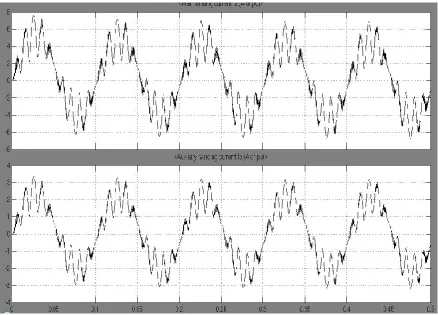
Figure4.MainWindingCurrent (b)AuxiliaryWinding CurrentWaveformof Single
PhaseInductionMotor, When InputFrequencyto theCycloconverterisTwoTimesOutputFrequency
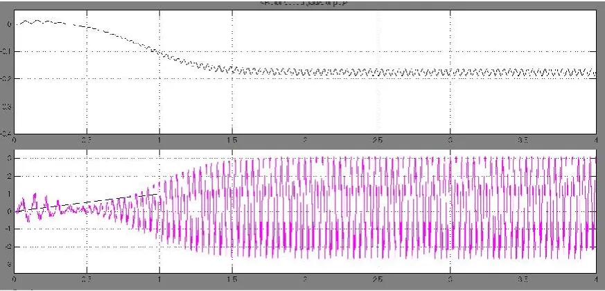
Figure5.(a)RotorSpeed(b)LoadandElectromagneticTorqueWaveformof Single
Figure6.(a)SourceVoltage(b)OutputVoltage(c)OutputcurrentWaveformofSinglePhasetoSingle
Phase CycloconverterWhen InputFrequencyisThreeTimesOutputFrequency
Figure8.(a)RotorSpeed(b)LoadandElectromagneticTorqueWaveformofSingle
PhaseInductionMotor, When InputFrequencyto theCycloconverterisTheeTimesOutputFrequency
Figure 10.(a)MainWindingCurrent (b)AuxiliaryWinding Current Waveformof SinglePhase Induction Motor, When InputFrequencyto the CycloconverterisFourTimesOutputFrequency.
Figure 12.(a)Source Voltage(b)OutputVoltage(c)OutputcurrentWaveform ofSinglePhasetoSingle Phase CycloconverterWhen InputFrequencyisFiveTimesOutputFrequency
Figure14.(a)RotorSpeed(b)LoadandElectromagneticTorqueWaveformof SinglePhaseInduction Motor, When InputFrequencyto theCycloconverteris fiveTimesOutputFrequency.
IV.
CONCLUSION
ThePWMcontrolledCycloconvertercircuits
isdesignedandsimulated anddesiredresults are obtained. Single phase Cycloconverter used forSinglephasemotortogeneratesupply torque characteristics that matches with demandtorque characteristics ofparticular machine by the use of designing Cycloconverterdifferentdesired frequency are obtained toequalizethe torquedemandof machine. Thisdifferentfrequency of Cycloconverterisalso usefultoreplace flywheelfrom theoperatingmachinewhich reducesthecause oftorsional vibrationand fatigue damage of machine. The paper proposedafeedback controlschemeof Cycloconverterfed split phase induction motor.Furthermore, itprovidesmeansfor limiting the slip and consequently the motor current.Thismeansa reductionin the Cycloconverterrating andbetterefficiency. This contribution willreporton the results obtainedusing matlabforsinglephase Cycloconvertercoupled toan induction motor.
V.
REFERENCES
[1]. Maamoun, A., "Development of cycloconverters," Canadian Conference on
Electrcal and Computer Engineering, 2003. IEEE CCECE Vol.1,4-7, pp.521 –524 May 2003.
[2]. Sandeep Pande , Harshit Dalvi, "Simulation of Cycloconverter Based Three Phase Induction Motor" International Journal of Advances in Engineering & Technology (IJAET), ISSN: 2231-1963 Vol. 1, Issue 3, pp.23-33 July 2011.
[3]. Shlomi Eitan and Raul Rabinovici, "On Line Simulation Models of Electric Drives" Proceedings of International Conference on Electrical Machines, 2008, 978-1-4244-1736-0/08, pp. 1-6 IEEE 2008.
[4]. Zahirrudin Idris, Mustafar Kamal Hamzah, and NgahRamzi Hamzah "Modeling & Simulation of a new Single-phase to Single- phase Cycloconverter based on Single-phase Matrix Converter Topology with Sinusoidal Pulse Width Modulation Using MATLAB/Simulink" pp.1557-1562 IEEE PEDS 2005.
Applied Power Electronics Colloquium (IAPEC), pp.189-194, 2011.
[6]. Rezgar Mohammed Khalil and Maamoon Al-Kababjie, "Modeling and Simulation of multi-pulse Cycloconvereter-fed AC induction motor and study of output power factor" Al- Rafidain Engineering Vol.15 No.1, pp. 1-14 2007. [7]. I. A. M. Abdel-Halim, H. G. Hamed, and K. M.
Hassaneen, "Modeling and Simulation of VSI-FED Induction Motors", Middle East Power Systems Conference (MEPCON’2000) pp.80-84, 2000.
[8]. D.M. Manjure and E. Makram "Effect of converter Drive on Power Systems", Middle East Power Systems Conference (MEPCON’2000), March 28-30, pp. 28-32, 2000.
[9]. Paul C. Krause, Oleg Wasynczuk, and Scott D. Sudhoff, "Analysis of Electric Machinery and Drive Systems", 2nd ed., ISBN: 978-0-471-14326-0, Wiley-IEEE Press, 2002.
[10]. Chen-Mun Ong, "Simulation of Electric Machinery", ISBN: 0-13-723785-5, Prentice Hall, NJ 07458, 1998.
[11]. Songchun Zhang, Fenglin Wu, Shmin Shen, Shuchun Yang, "A Digital Controller Based Cycloconverter Fed Drive", pp. 637-641,EEE Transaction, 1997.
[12]. Z.Wang and Y. Liu, "Modeling and Simulation of a Cycloconverter Drive System for Harmonic studies", IEEE Transactions on Modern Electronics, vol. 47, no. 3, , pp. 533-541, June 2000.