IJSRSET17325 | Received : 01 March-2017 | Accepted : 08- March -2017 | March-April - 2017 [(3)2: 08-13 ]
© 2017 IJSRSET | Volume 3 | Issue 2 | Print ISSN: 2395-1990 | Online ISSN : 2394-4099 Themed Section: Engineering and Technology
8
FEA Analysis of Two Wheeler Silencer
Namrata Agrawal
1, Santosh Devkare
21,2
Department of Mechanical Engineering, SSJCOE, Asangaon, Maharashtra, India
ABSTRACT
The present study simulates a practical system such as a silencer. A conventional muffler used in vibratory rollers is usually designed based on experience and its performance could be enhanced in a large degree through structure optimization. In this work modal analysis is done for mode shape finding for existing silencer. It is done to distinguish it from the working frequency to avoid resonating condition. The dimensions of the existing model of the silencer will be referred as benchmarking dimensions to create modified model. Frequency response analysis is carried out to study behaviour of silencer at different frequencies and free free analysis is done with the help of ANSYS 16.0.
Keywords : Acoustic Insertion Loss, Flow Field, Pressure Loss, Reactive Muffler, Model, Heat Transfer.
I.
INTRODUCTION
One of the objectives while designing a new automobile exhaust pipe is to lengthen it's durability period, which can be measured in terms of its life span and mileage. The exhaust pipe is subjected to several stresses, most of which are due to vibration. Particular attention should be given to gas forces which will induce vibration. These vibrations will then induce a fatigue life to the system. It is therefore necessary to study the fatigue behavior of the exhaust pipe by analyzing the vibration modes and the response of vibrations by its sources. The purpose of the exhaust system is simple: to channel the fiercely hot products of fuel combustion away from the engine or generator and the car's occupants and out into the atmosphere. The exhaust system has a secondary purpose- to reduce the amount of noise made. The exhaust gases leave the engine at incredibly high speeds. Moreover, with the opening and shutting of the exhaust valves with each cycle of combustion for each cylinder, the gas pressure alternates from high to low causing a vibration- and hence sound.
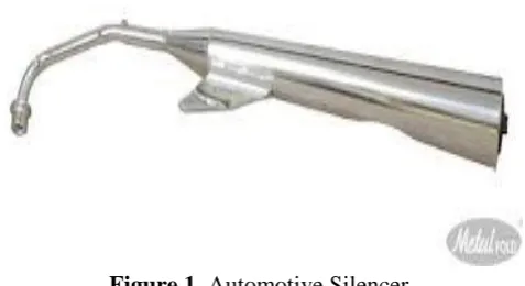
Figure 1. Automotive Silencer
and mufflers. Generally speaking, there is no technical distinction between a silencer and muffler and the terms are frequently used interchangeably. A silencer has been the traditional name for noise attenuation devices, while a muffler is smaller, mass-produced device designed to reduce engine exhaust noise.
Practically, the exhaust gas mass is forced through the pipe after leaving the engine. Its momentum forces the change in the direction of motion, or in the expansion or contraction of the end pipe. This gas produces some resonance in such frequency range that might cause fatigue failure to the exhaust pipe when the resonance exists continuously. Without the consideration of these cases, the development of the exhaust system will be incomplete.
II.
METHODS AND MATERIAL
A. Literature Review
Yunshi Yao et al [1] studied the performance of reactive muffler and its effect on power loss of engine, flow field of muffler was discussed by CFD comparing with experimental test and the structure of reactive muffler was optimized. Based on results of simulation and optimization, the reactive muffler used in vibratory rollers with weight of 13t was fabricated and its field test was carried on. The simulate results showed that velocity field coincided with the pressure field basically, which indicates that the optimized muffler has excellent aerodynamic characteristics and rational design of damping units. The results of field tests showed that 2# muffler had better acoustic insertion loss with little pressure loss. Acoustic insertion loss was 17~18.4 dB (A) at engine speed of 2450 rpm, which meets the designing goal.
Lian-yun LIU et al [2] studied the multi-dimensional computational fluid dynamics (CFD) approach was proposed in this study aiming to calculate the transfer matrix of an engine exhaust muffler in the conditions with and without mean flow. The CFD model of the muffler with absorptive material defined as porous zone was calibrated with the measured noise reduction without mean flow, and was further employed to study the effect of the mean flow on the acoustic performance of the muffler. Furthermore, the exhaust acoustical source was derived from the calculated transfer matrices of six different additional acoustic loads obtained by the proposed CFD approach as well as the measured tail
noise based on a multiload least squares method. Finally, the exhaust noise was predicted based on Thevenin‟s theorem. The proposed CFD approach was suggested to be able to predict the acoustic performance of a complex muffler considering mean flow (without and with mean flow) and heat transfer, and provide reasonable results of the exhaust noise.
H.-D. Kim et al. [3] addresses a computational work of the weak shock wave propagating inside a silencer system of automobile exhaust pipe. The second order total variation diminishing (TVD) scheme is employed to solve the two-dimensional, compressible, unsteady, Euler equations. Eight different models of the silencer systems are explored to investigate the effects of the silencer configuration that has on the weak shock wave propagation phenomena. The incident plane shock wave is assumed at the inlet of the silencer and its Mach number is changed between 1.01 and 1.30. The present computational analysis clearly reveals the detailed shock wave reflections/diffractions and vertical flows inside the silencer models. These results are detailed by the pressure time histories at several locations inside the silencer model. Of the eight different silencers applied, the silencer model with a series of the baffle plates inside the expansion chamber reduces the first peak pressure at the exit of the exhaust pipe by about 27%. The present computational results predict the experimental results with a quite good accuracy.
Takashi Yasuda, Chaoqun Wu, Noritoshi Nakagawa, Kazuteru Nagamura [4] studied automotive muffler experimentally and numerically under the condition of wide open throttle acceleration in this paper. The transient acoustic characteristics of its exhaust muffler were predicted using one dimensional computational fluid dynamic. Validations of the results obtain by the simulation, of the muffler for transient acoustic characteristics were measured in an anechoic chamber. Experimental results are in good agreement with simulation results at the 2nd order of engine rotational frequency. But for higher orders, there are differences between the experimental results and the simulation results, especially at the high engine speed.
enclosure with heated baffles on side walls. The numerical solution indicates that increasing the value of Re and Ri leads to higher intensity of recirculation and complex fluid flow characteristics. All walls are assumed to be adiabatic, but baffles are considered as isothermally heated. Maximum heating efficiency has been occur with higher value of Re and Ri and it increases gradually with both the increase of Re and Ri. Aminudin Abu [6] presents the study of the dynamic characteristics using the theoretical approach to the mathematical model of the whole exhaust pipe. This would give enough information to designers to develop a new exhaust pipe. The fatigue behavior of the exhaust pipe is analyzed theoretically with its vibration modes. The result obtained by FEM is also compared with Transfer matrix method. In this paper the location of hanger position are detected for increasing the natural frequency of silencer. Throughout the modes, the hanger location might be defined by detecting and considering the modes on that system.
B. Objectives
- CAD modeling of existing silencer.
- Modal Analysis of silencer using FEA software for mode shapes finding.
C. Silencer Selection Factor
The use of an exhaust silencer is prompted by the need to reduce the engine exhaust noise. In most applications the final selection of an exhaust silencer is based on a compromise between the predicted acoustical, aerodynamic, mechanical and structural performance in conjunction with the cost of the resulting system.
1. Acoustical Performance
The acoustical performance criterion specifies the minimum insertion loss (IL) of the silencer, and is usually presented in IL values for each octave band as well as an overall expected noise reduction value. Octave bands and sound attenuation are discussed in further detail in Chapter 25. The insertion loss is determined from the free-field sound pressure levels measured at the same relative locations with respect to the outlet of the unsilenced and silenced systems. The IL of a silencer is essentially determined by measuring the noise levels of piping systems before and after the insertion of a silencer in the exhaust stream. IL data
presented by most manufacturers will typically be based upon insertion of the silencer into a standard piping system consisting of specified straight runs of piping before and after the silencer. Exhaust system configurations as well as mechanical design can have a substantial impact on the performance of and exhaust silencer and should be considered at the time of specification. Raw exhaust noise levels should be obtained from the engine manufacturer to determine the necessary noise reduction requirements of the proposed silencer. Specific installation conditions and exhaust noise levels will aid the manufacturer in determining the correct silencer to meet the required noise reduction. If a silencer is located outside of the room or housing in which the engine is installed, one must be cognoscente of the effects of „break-out‟ noise from either the silencer body or associated piping system. Breakout noise can dominate the stack radiated noise, particularly for high performance silencers that greatly reduce the noise transmitted downstream. A high performance exhaust silencer may have extremely good IL performance, but utilization of a thin walled piping system may allow substantial noise to be radiated from the piping system before entering the silencer body. One solution avoids potential breakout from dominating the overall noise levels is to ensure a balance between the exhaust silencer shell thickness and corresponding piping. Manufacturers will often incorporate a multiple layer shell on higher-grade silencers to increase the transverse transmission loss of the silencer.
2. Aerodynamic Performance
results. The pressure drop through silencers should be obtained from the manufacturer of the product upon submission of the required flow information.
3. Mechanical Performance
The Mechanical performance criterion specifies the material properties of the exhaust system to ensure that it is durable and requires little maintenance when incorporated into service. Material selection is especially important in cases involving high temperature or corrosive gases. Traditional carbon steels will typically be sufficient for the majority of applications using Diesel fueled generators. Natural Gas engines will traditionally run at an elevated temperature above their Diesel counterpart, and may require a graded carbon or stainless steel that can maintain an element of structural performance at elevated temperatures. Aluminized steel is available from many silencer manufacturers and is often preferred for general applications. Aluminized steel is slightly more heat resistant than carbon steel and offers an increased resiliency to corrosion and is often selected as an economical alternative to specifying a stainless steel system. Regular periodic testing of a standby generator will subject the exhaust system to thermal cycles that can contribute to the premature corrosion of carbon steel.
4. Structural Performance
The Structural performance criterion can specify the geometric restrictions and/or maximum allowable volume/weight of the silencer that can substantially influence the silencer design process. Secondary loading outside of the weight of the silencer can also affect the design and cost of the exhaust system. A standard engine silencer is not traditionally designed to absorb substantial loads due seismic activity, wind or thermal growth of adjacent piping. Silencers that are specifically incorporated as an element of an exhaust “stack” should be designed to accommodate the loads that will be absorbed due to potentially high wind loads as well as seismic activity. A commodity purchased silencer should be isolated from substantial piping runs through the use of flexible expansion joints to reduce or eliminate the transfer of loads and engine vibration. Customized silencers can easily be designed when the force and moment values that can be placed on a connection are indicated at the time of quotation.
III.
RESULTS AND DISCUSSION
Silencer Modelling
CAD Drawing
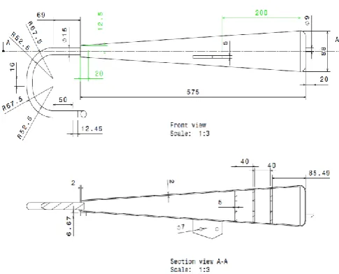
Figure 1. 2D drawing of silencer
Figure 2. 3D model of silencer
VI. SILENCER MODAL ANALYSIS
6.1 Modal Analysis of Silencer
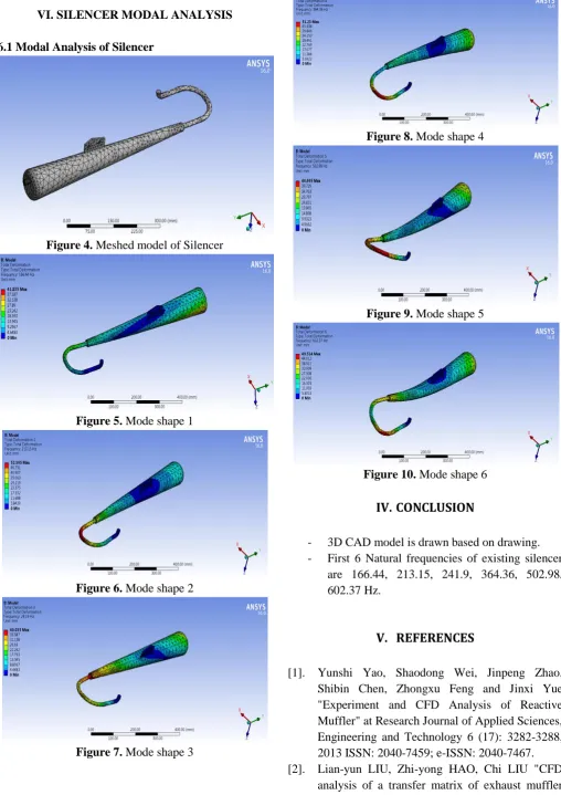
Figure 4. Meshed model of Silencer
Figure 5. Mode shape 1
Figure 6. Mode shape 2
Figure 7. Mode shape 3
Figure 8. Mode shape 4
Figure 9. Mode shape 5
Figure 10. Mode shape 6
IV.
CONCLUSION
- 3D CAD model is drawn based on drawing. - First 6 Natural frequencies of existing silencer
are 166.44, 213.15, 241.9, 364.36, 502.98, 602.37 Hz.
V.
REFERENCES
[1]. Yunshi Yao, Shaodong Wei, Jinpeng Zhao, Shibin Chen, Zhongxu Feng and Jinxi Yue "Experiment and CFD Analysis of Reactive Muffler" at Research Journal of Applied Sciences, Engineering and Technology 6 (17): 3282-3288, 2013 ISSN: 2040-7459; e-ISSN: 2040-7467. [2]. Lian-yun LIU, Zhi-yong HAO, Chi LIU "CFD
with mean flow and prediction of exhaust noise" at Journal of Zhejiang University-SCIENCE A (Applied Physics & Engineering) ISSN 1673-565X (Print); ISSN 1862-1775 2012 13(9):709-716.
[3]. H.D. Kim, Y.H. Kweon, T Setoguchi, "A study of the weak shock wave propagating through an engine exhaust silencer system" Journal of Sound and Vibration, Volume 275, Issues 3-5, 23 August 2004, pp. 893-915.
[4]. Takashi Yasuda , Chaoqun Wua, Noritoshi Nakagawa, Kazuteru Nagamura,"Predictions and experimental studies of the tail pipe noise of an automotive muffler using a one dimensional CFD model", Applied Acoustics 71 (2010) 701–707. [5]. M. R. Asif, M. S. Hossain and K. A.
Hossain,"Heat Transfer In A Rectangular Enclosure With Baffles", ARPN Journal of Engineering and Applied Sciences, VOL. 6, NO. 4, APRIL 2011.