R E S E A R C H
Open Access
Design of Micro-strip Symmetrical
Dual-band Filter Based on Wireless Sensor
Network Nodes
Wenbo Cheng
1,2*, Kai Deng
1and Wei Cheng
3Abstract
The micro-strip antenna filter design of wireless sensor network nodes is usually used to improve the out-of-band suppression and frequency selectivity by increasing the order of the filters, but the filters are usually single band, not only the size is large, but also the in-band characteristics of the filters are not ideal. This paper proposes a method to design a micro-strip symmetric dual-band filter in wireless sensor network nodes. Firstly, the coupling matrix of single-passband filter is obtained by using the synthesis method of generalized Chebyshev filter function. Then, the coupling matrix of the dual-passband filter is generated according to the reflection zeros and the transmission zeros. Finally, theS
parameters response curve is drawn by mapping the normalized frequency domain of the dual-passband to the actual frequency domain. According to the data analysis and experimental results, the method is feasible and effective to design a micro-strip symmetrical dual-band filter. It can not only provide a more guiding design method for the joint design of antenna and RF front-end circuit, but also realize the spread of single-passband filter to multi-frequency for a wireless sensor network node antenna.
Keywords:Wireless sensor network nodes, Symmetrical dual-passband technology, Micro-strip antenna, Generalized Chebyshev function, Cross-coupling synthesis theory, Transmission zeros
1 Introduction
The traditional radio frequency (RF) transceiver system consists of antenna, filter, power amplifier, low noise amplifier, and other devices, which often work under a single communication standard. If multiple communica-tion standards run at the same time, it requires multiple independenttransceiver systems to form a parallel work-ing system which will be larger in size, high in power consumption and high in cost, and has been unable to meet the application needs of wireless sensor network nodes in the era of the big data, which has attracted the attention and widespread concern of researchers all over the world [1–13].
Micro-strip filter is a very important component of wireless sensor network (WSN) nodes, which is used to select useful signals and suppress clutter interference
signals. Multi-frequency micro-strip filters are required to effectively pick up the signals of each separate fre-quency band and prevent signal crosstalk between adjacent channels, which requires higher frequency se-lectivity and out-of-band rejection of the filters [4–6]. In recent years, scholars in various countries have carried out in-depth research and proposed various design methods to solve the two core problems in the design of multi-band micro-strip filters [14–20]: Firstly, multi-point frequency selection can be realized, multi-fre-quency can work in parallel, and each central fremulti-fre-quency point has a certain capacity bandwidth; secondly, the signals in adjacent frequency bands must be effectively isolated and can not interfere with each other, and the out-of-band rejection performance of the filter is reliable. There are two main methods for designing multi-band filters [21–35]: Firstly, based on the combination of multi-band filters, including the cascade of broadband fil-ters and notch filfil-ters, and the parallel connection of mul-tiple filters in different frequency bands; secondly, based
* Correspondence:[email protected]
1
School of Physics and Electronic Engineering, Yibin University, Ybin 644000, China
2Key Lab of Earth Exploration & Information Techniques of Ministry of
Education, Chengdu University of Technology, Chengdu 610059, China Full list of author information is available at the end of the article
on the parasitic frequency of resonators, a multi-band filter is designed.
Traditional Butterworth, Chebyshev, and elliptic func-tion filters can increase the design order of the filter to improve the filter’s out-of-band suppression and fre-quency selectivity, but the designed filter is usually single-band, not only the size is large, but also the filter’s in-band characteristics are not ideal [36]. Generalized Chebyshev filter (GCF) is also known as quasi-elliptic function filter. It is between Chebyshev and elliptic func-tion filter, which has excellent in-band characteristics and steep edge characteristics [37,38]. The transmission zeros of generalized Chebyshev filter can be flexibly con-trolled, which can be used to improve filter selectivity and stop-band isolation. In order to improve the in-band and out-of-band performance of the filter, the communi-cation band of the filter is extended from a single band to a dual band. Based on the synthesis theory of general-ized Chebyshev filter, the frequency transformation is carried out with low-frequency prototype, and the design from low-frequency prototype to dual-band filter is real-ized with a cross-coupling synthesis theory.
2 Methodology
2.1 Frequency conversion method of symmetrical dual band
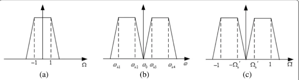
The single-band filter model is transformed into a dual-band filter and has to undergo two frequency con-version. Firstly, the normalized single low-pass filter is transformed into a normalized dual-band filter, and then, the normalized dual-band filter is transformed into a dual-band filter of actual frequency by one transform-ation. Figure1 shows that three frequency variables are applied in the frequency conversion process, one is the normalized low-pass frequency variable Ω, the other is the dual-band normalized intermediate variable Ω′, and the third is the actual frequency variableω.
The transmission function of the generalized Cheby-shevN-order low-pass filter [35] is shown as below
T2ð Þ ¼s S2 21ð Þ ¼s
1 1þε2C2
Nð Þs ð
1Þ
Among them,s=jΩ, εis the ripple coefficients in the passband and CN(s) is the characteristic function of the generalized Chebyshev low-pass filter.
The transmission zeros and reflection zeros of the generalized Chebyshev low-pass filter are described.
CNð Þ ¼ω FPð Þð Þωω ¼ QN
i¼1 s−spi
QK j¼1 s−szj
ðK≤NÞ ð2Þ
Among them,spiis the transmission pole, also known as the reflection zero, that is the filter power optimal transmission point andszjis the transmission zero.
It is assumed that the transmission function of the generalized Chebyshev low-pass filter is about Ω axis symmetry. The dual-band frequency conversion process is shown in Fig. 1. Thus, the number of transmission zeros and reflection zeros of the generalized Chebyshev dual-band filter obtained by frequency transformation is 2K and 2N, respectively. The low passband frequency range js' is−jto−jΩ0k, and the high passband frequency range js' is jΩ0ktoj.
Firstly, the normalized frequency conversion from sin-gle passband to double passband is realized. The frequency conversion equations such as Eqs. (3) and (4) are given.
s¼a1s0 þa2s0 ðΩ0>0Þ ð3Þ
s¼‐ a1s0 þa2s0
Ω0<0
ð Þ ð4Þ
s′ is a frequency variable that is mapped from the prototype s plane. As shown in Fig. 1, when s changes from normalized frequency−1 to 1 in theΩ domain, it maps to s′ from normalized frequency Ω0k to 1 in the
Ω′> 0 domain; when s changes from normalized
frequency −1 to 1 in theΩ domain, it maps to s′ from normalized frequencyΩ0k to 1 in theΩ′> 0 domain. De-generate (3) into
s02−sa1s0þa1a2¼0 ð5Þ
The following Eq. (6) can be obtained by expression (5) of whichs=jΩ.
s0¼ jΩa1ja1
ffiffiffiffiffiffiffiffiffiffiffiffiffiffiffiffiffiffiffiffiffiffiffi
Ω
ð Þ2þ4a2 a1 r
2 ð6Þ
When s=j, s′=j or when s¼−j; s0¼ jΩ0k, the Eq. (7) can be obtained from the Eq. (6).
1¼a1 2 1þ
ffiffiffiffiffiffiffiffiffiffiffiffiffiffiffiffiffiffiffiffiffiffi 1þ4a2=a1 p
Ωk0¼a1 2 1−
ffiffiffiffiffiffiffiffiffiffiffiffiffiffiffiffiffiffiffiffiffiffi 1þ4a2=a1 p
ð7Þ
We can get s=j when s′=j and s0¼−jΩ0k; s¼−j when s′=−j and s0¼ jΩ0k from Fig. 1. Therefore, the following expressions can be obtained.
a1¼1‐Ωk0 ; a2¼ Ωk
0
1‐Ωk0 ð8Þ
Thus, the normalized single passband to normalized dual-band frequency conversion can be easily realized by expressions (7) and (8).
Secondly, the normalized dual-band to the actual quency of the dual-band transformation, that is, the fre-quency transform domain fromΩ′domain toωdomain transformation. The transformation equation is
s0¼ϖ
l1 þ l2
ϖðω>0Þ ð9Þ
Among it,ϖ=jω. We can see that values of 1, Ω0k; −
Ω0
k, and −1 in the Ω′domain are mapped, respectively, toωk4, ωk3, ωk2, andωk1of theωdomain from Fig.1.
We can get the expressions ofl1, l2, andΩ0k.
l1¼ωk4−ωk1; l2¼ωωk4ωk1
k4−ωk1; Ωk
0¼ωk3−ωk2 ωk4−ωk1
ð10Þ
2.2 Synthesis method ofN-order cross-coupling matrix
With the development of communication technology, the spectrum is becoming more and more crowded, and the technical specifications of the filter, especially the rectangular requirements, are becoming more and more stringent. Traditional Butterworth and Chebyshev filters have been unable to meet the requirements. In order to improve the selectivity and out-of-band isolation of ters, transmission zeros are usually introduced into fil-ters, which are generated by cross-coupling between non-adjacent resonators [30–35]. The cross-coupling fil-ter with finite transmission zeros is the most common choice. Generalized Chebyshev function is usually used to implement it.
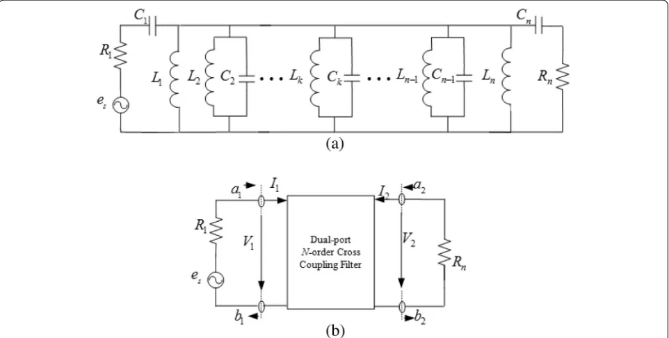
The lumped parameter equivalent circuit and equivalent network parameters of the coupling filter are shown in Fig. 2a and b, respectively. According to the Kirchhoff theorem that the sum of the voltage is
zero along the loop, the voltage of each loop is
de-The specific method of treatment is shown in document [15], Eq. (11) which is expressed by matrix as Eq. (12).
Z
½ ½ ¼I ½ e ð12Þ
[Z] is N×N impedance matrix. Each resonator of syn-chronous tuning filter has the same resonance frequency
ω0¼1=
Table 1Polynomial roots of the four-order single-passband filter
Functions Transmission zeros, the roots ofP(Ω)
Reflection zeros, the roots ofF(Ω)
Transmitting or reflecting singularities, the roots ofE(Ω)
1 −1.5j −0.9424j −0.7964 + 1.020j
2 1.5j 0.9424j −1.2310 + 0.1914j
3 − ∞ −0.4299j 0.7964 + 1.020j
4 ∞ 0.4299j 1.2310 + 0.1914j
a1¼ es
2pffiffiffiffiffiR1 b1¼
es−2i1R1
2pffiffiffiffiffiR1
a2¼0 b2¼inpffiffiffiffiffiRn
ð15Þ
After synthesizing the coupling matrix, the coupling matrix is deformed to correspond to the actual circuit model structure. This is advantageous to the actual physical circuit design, in which the negative coupling coefficient in the coupling matrix represents the cap-acitance coupling in the cross-coupling of the adja-cent resonator circuit, and the positive coupling coefficient in the coupling matrix represents the in-ductive coupling in the cross-coupling of the adjacent resonator circuit.
3 Results and discussion
3.1 Basic parameters of dual-band filter
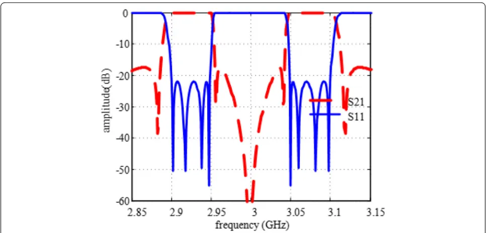
Based on the previous generalized Chebyshev filter func-tion synthesis theory of dual-band filter, a symmetrical dual-band filter (SDF) are designed. Assuming that the frequency range of the low passband is 2.9–2.95 GHz, the frequency range of the high passband is 3.05–3.10 GHz and the in-band return loss is RL = 22 dB.
The dual-band is symmetrical with respect to the center of ω0= 3 GHz, and the four transmission zeros of the single-pass low-pass filter are 1.5j, −1.5j, j∞, and−j∞.
ωk1= 2.90, ωk2= 2.95, ωk3= 3.05, and ωk4= 3.10 can be calculated from the conditions given above. Accord-ing to Eq. (10), we can obtain Ω0k¼0:5 . According to Eq. (8), we can obtaina1= 0.5 anda2= 1.
3.2 Design and simulation of symmetrical dual-band filter
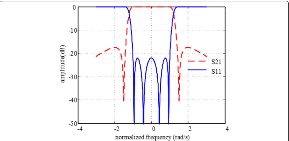
Based on the generalized Chebyshev filter synthesis method described in the previous section, we can obtain the roots of these functions P(Ω), F(Ω), and E(Ω), as shown in Table1.
Pð Þ ¼Ω Ω2−2:25
Fð Þ ¼Ω Ω4−1:730Ω2þ0:1641 ε−0:8666
Eð Þ ¼Ω Ω4−j2:423Ω3−4:009Ω2þj3:81Ωþ2:601
We can plot the response curve of theSparameter, as shown in Fig.3. The coupling matrix [16] deduced from short-circuit admittance parameters is:
m¼
0 0:861 0 −0:476 0:861 0 −0:911 0
0 0:911 0 −0:861
−0:476 0 −0:861 0
2 6 6 4
3 7 7 5
Now, by using the frequency mapping equation, the re-flection and transmission zeros of single-passband normal-ized generalnormal-ized Chebyshev function filters and a1= 0.5, a2= 1 are substituted in Eq. (6), we can obtain:
s0¼jΩa1ja1
ffiffiffiffiffiffiffiffiffiffiffiffiffiffiffiffiffiffiffiffiffiffiffi
Ω
ð Þ2þ4a2 a1 r
2 ¼
j0:5 Ω
ffiffiffiffiffiffiffiffiffiffiffiffiffiffiffiffiffiffi
Ω
ð Þ2þ 8 q
2
ð16Þ
The transmission and reflection zeros of dual-band filters are obtained by using Eq. (16). Then, the root of
E(s′) is obtained by using the generalized Chebyshev fil-ter function synthesis of a symmetrical dual-band. The roots ofP(Ω′), F(Ω′), andE(Ω′) are listed in Table2.
Pð Þ ¼Ω0 Ω06þ
1:5625Ω04þ0:25Ω02
Fð Þ ¼Ω0 Ω08þ
2:2682Ω06þ1:7785Ω04þ0:56706Ω02
þ0:0625
EΩ0¼Ω08þ1:119Ω07þ2:895Ω06þ2:087Ω05þ2:524Ω04
þ1:044Ω03 þ0:723Ω02þ0:1399Ω01þ0:062
Especially, the filter is a four-order filter, with two finite transmission zeros, and two transmission zeros located at the positive and negative infinity. In the case of dual-pass-band transformation, the transmission zeros at infinity of single passband correspond to the transmission zeros at
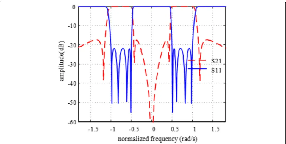
zero of dual passband. After the transmission and reflection zeros of the two passbands are obtained, the expressions of each polynomial of the two passbands can be obtained by using the synthesis method of the generalized Chebyshev filter function.
Thus, the normalized response curve of the dual band-pass filter can be obtained, as shown in Fig.4.
Finally, Eq. (10) is used to calculatel1andl2, and the Eq. (17) are used to map the frequency domain fromΩ′toω domain. Then, the S parameter curve in the actual fre-quency domain is obtained as shown in Fig.5.
ω¼l1
2 Ω
0þpffiffiffiffiffiffiffiffiffiffiffiffiffiffiffiffiffiffiffiffi1þ4l2=l1
ð17Þ
The coupling matrix obtained from the coefficients of P(Ω′), F(Ω′), and E(Ω′) are then rotated to eliminate Fig. 5Sparameters response curve of dual-passband actual frequency
Table 2Polynomial roots of the eight-order dual-band filter
Functions Transmission zeros, the roots ofP(Ω′)
Reflection zeros, the roots ofF(Ω′)
Transmitting or reflecting singularities, the roots ofE(Ω′)
1 1.175j 0.5097j −0.0656 + 1.066j
2 0.4254j −0.9809j −0.0656−1.066j
3 −0.4254j 0.9809j −0.1711 + 0.5115j
4 −1.175j −0.5097j −0.2941 + 0.8791j
5 0 0.6078j −0.2941−0.8791j
6 0 −0.6078j −0.0287−0.4673j
7 – −0.8227j −0.1711−0.5115j
the element. The folded N+ 2-order, that is, the tenth-order coupling matrix is.
4 Conclusion
This paper presented an experimental study on the micro-strip dual-band filter based on wireless sensor network nodes. Firstly, according to the order, the pos-ition of the transmission zeros, and the ripple coeffi-cients in the band of the filter to be designed, the generalized Chebyshev filter function synthesis method is applied to synthesize a single-passband filter by com-bining the relationship between the short-circuit admit-tance parameters. The coupling matrix of the single-passband filter is obtained. Secondly, the generalized Chebyshev function polynomial is constructed according to the symmetrical frequency conversion equations from single-band to dual-band, and the coupling matrix of the dual-band filter is synthesized by the relationship be-tween the generalized Chebyshev function polynomial and the short-circuit admittance parameters. Finally, the normalized frequency domain is mapped to the actual frequency domain, and the S parameter response curve in the actual frequency domain is obtained. By flexibly controlling the transmission zeros of the generalized Chebyshev filter, the selectivity and stop-band isolation of the filter can be effectively improved, and this method can design multi-band filters with excellent performance and has a positive guiding role in the physical circuit de-sign of micro-strip filters based on wireless sensor net-work nodes.
Abbreviations
GCF:Generalized Chebyshev filter; RF: Radio frequency; SDF: Symmetrical dual-band filter; WSN: Wireless sensor networks
Acknowledgements
The research presented in this paper was supported by National Natural Science Foundation, Sichuan Provincial Education Department and Yibin University, China.
Funding
The authors acknowledge the Scientific Research Fund of Sichuan Provincial Education Department (Grant: 14ZA0269), Scientific Research Key Project of
Yibin University (Grant: 2013QD02) and the National Natural Science Foundation of China (Grant: 61201266).
Availability of data and materials
The simulation code can be downloaded by contacting author after three years of publication. Mostly, I got the writing material from different journals as presented in the references. MATLAB tool has been used to simulate my concept.
Authors’contributions
WBC is the main author of this manuscript. He conceived the novel ideas, designed the algorithms and experiments, and performed the analysis. He wrote the entire manuscript. He accomplished all the revisions provided during entire peer review process until publication. He conducted the final proof reading as well. This manuscript is the outcomes of the research activities carried out only by the main author. KD and WC checked, reviewed the manuscript, and gave valuable suggestions on the structure of the paper. All authors have read approved the final manuscript.
Competing interests
The authors declare that they have no competing interests.
Publisher’s Note
Springer Nature remains neutral with regard to jurisdictional claims in published maps and institutional affiliations.
Author details
1
School of Physics and Electronic Engineering, Yibin University, Ybin 644000, China.2Key Lab of Earth Exploration & Information Techniques of Ministry of
Education, Chengdu University of Technology, Chengdu 610059, China.
3Network and Multimedia Management Center, Yibin University, Ybin
644000, China.
Received: 21 October 2018 Accepted: 11 January 2019
References
1. H.T. Hsu, F.Y. Kuo, P.H. Lu, Design of WiFi/WiMAX dual-band E-shaped patch antennas through cavity model approach. Microw. Opt. Technol. Lett.52(2), 471–474 (2010)
2. J. Xu, W. Wu, Compact microstrip dual-mode dual-band band-pass filters using stubs loaded coupled line. Prog. Electromagn. Res. C.14, 137–150 (2013)
3. X.L. Peng, X.C.H. Wei, The resonance principle and designing method of multi-bands micro-strip antenna with branch shape. J. Antennas2(4), 21–26 (2013)
4. W. Liu, M. Wang, W. Wu, Design on bi-directional circularly polarized micro-strip antenna for mobile communication. J. Antennas3(2), 9–14 (2014)
5. D.Y. Wang, M. Wang, Y. Yuan, W. Wu, Design of broad band micro-strip antenna at S band. J. Antennas4(3), 17–24 (2015)
6. Y. Yuan, M. Wang, D.Y. Wang, W. Wu, Design of broadband circularly polarized microstrip antenna at S band. J. Microwaves33(4), 36–40 (2017) 7. S. Yang, J. Chen, K. Deng, Design of compact dual-band band-pass filter
using dual-mode stepped-impedance stub resonators. Electron. Lett.50(8), 611–613 (2014)
8. S.S. Gao, S. Sun, J.L. Li, Compact dual-mode dual-band band-pass filter with inside-outside-reversed dual-ring topology. Electron. Lett.53(9), 624–626 (2017)
9. K. Zhou, C. Zhou, W. Wu, Substrate integrated waveguide dual-band filter with wide-stop band performance. Electron. Lett.53(16), 1121–1123 (2017) 10. W.B. Cheng,Construction of WSN and application of localization for in-home healthcare of the elderly. Appl. Mech. Mater., vol 263-266 (2013), p. 943–947 11. W.B. Cheng, K. Deng, A novel indoor localization algorithm design for
in-home healthcare of the elderly based on WSN. Open Cybern. Syst. J.8(1), 1280–1285 (2014)
12. W.B. Cheng, W. Cheng, K. Deng, G. Guan, A tracking algorithm design for indoor mobile target based on EKF. J. Residuals Sci. Technol.13(5), 133.1– 133.7 (2016)
13. W.B. Cheng, H.J. Wang, The key techniques of mine personnel localization system based on wireless sensor network. Microelectron. Comput.29(4), 165–168 (2012)
14. G.L. Matthaei, L. Young, E.M.T. Jones.Microwave filters, impedance-Matching networks, and coupling structures.(Artechic House Publishers, 1980), p. 83-723
15. J.S. Hong, M.J. Lancaster,Microstrip Filters for RF/Microwave Applications.
(Wiley, 2001), p. 29-77
16. R.J. Cameron, C.M. Kudsia, R.R. Mansour.Microwave filters for
communicationsystems: fundamentals, design and applications.(Wiley, 2007), p. 427-858
17. Y. Yin, M. Wang, R. Xu, W. Wu, Design of wideband harmonic rejection antenna. J. Antennas6(1), 1–6 (2017)
18. N. Kumar, Y.K. Singh, Compact tri to dual pass-band switch-able band-pass filter using stub-loaded split-ring resonator with improved bandwidth. Electron. Lett.51(19), 1510–1512 (2015)
19. F. Wei, Y.J. Guo, X.W. Shi, Design of multi-band band-pass filters based on stub loaded stepped-impedance resonator with defected micro-strip structure. IET Microwaves, Antennas Propag.10(2), 230–236 (2016) 20. J. Xu, Y. Zhu, Compact semi-lumped dual- and tri-wideband band-pass
filters. IET Microwaves Antennas Propag.11(1), 53–58 (2017)
21. P.C. Zhao, Z.Y. Zong, W. Wu, A fuss structure based on parallels resonators for multi-band applications. IEEE Trans. Antennas Propag.65(10), 5257–5266 (2017) 22. X. Shang, Y. Wang, G.L. Nicholson, Design of multiple-pass-band filters
using coupling matrix optimization. IET microwaves. Antennas Propag.
6(1), 24–30 (2012)
23. H. Zhang, W. Kang, W. Wu, Differential substrate integrated waveguide band-pass filter with improved common-mode suppression utilising complementary split-ring resonators. Electron. Lett.53(7), 508–510 (2017) 24. S. Zhang, J.Y. Rao, J.J. Cheng, Novel compact single-band and dual-band band-pass filter based on one-third-mode substrate integrated waveguide. IEICE Electron. Express14(19), 153–156 (2017)
25. M.D. Hickle, D. Peroulis, Tunable constant-bandwidth substrate-integrated band-stop filters. IEEE. Trans. Microwave Theory Tech.66(1), 157–169 (2018) 26. B. Lee, B. Koh, S. Nam, Band-switchable substrate-integrated wave-guide
resonator and filter. IEEE. Trans. Microwaves Theory Tech.66(1), 147–156 (2018) 27. U. Naeem, M.B. Khan, M.F. Shafique, Design of compact mode
dual-band SIW filter with independent tuning capability. Microw. Opt. Technol. Lett.60(1), 178–182 (2018)
28. D. Bukuru, K. Song, F. Zhang, Compact quad-band band-pass filter using quad-mode stepped impedance resonator and multiple coupling circuits. IEEE. Trans. Microwaves Theory Tech.65(3), 783–791 (2017)
29. S. Butterworth, On the theory of filter amplifiers. Exp. Wireless Eng.7(6), 536–541 (1930)
30. D.D. Pang, Y. Xiong, M. He, L. Ji, J.L. Zhang, New quaint-band multimode filter with multiple transmission zeros. Electron. Components Mat.36(10), 67–72 (2017)
31. Y.L. Zhang, T. Su, B. Wu, R.J. Zhou, Optimization synthesis technique for cross-coupled filter with frequency dependent couplings. J. Univ. Electron. Sci. Technol. China47(4), 516–520 (2018)
32. J. Xu, W. Wu, G. Wei, Compact multi-band band-pass filters with mixed electric and magnetic coupling using multiple-mode resonator. IEEE Trans. Microwave Theory Tech.63(12), 3909–3919 (2015)
33. F. Zhang, Y. Xiong, W. Zhang, D.D. Pang, X. Zhang, Tunable band pass filter based on cross-coupled structure. Electron. Components Mat.37(5), 67–72 (2018) 34. C.H. Sun, T. Feng, Cross-coupled bandpass filter with microstrip lines.
Electron. Components Mat.35(12), 54–56 (2016)
35. R.B. Ma, J.G. Yan, X.W. Chen, L.Y. Yan, L.P. Han, Design of the novel miniaturized cross-coupled band-pass filter. J. Test Meas. Technol.30(1), 69– 73 (2016)
36. R.J. Cameron, Fast generation of Chebyshev filter prototypes with asymmetrically-prescribed transmission zeros. ESA J.6(1), 83–95 (1982) 37. R.J. Cameron, General coupling matrix synthesis methods for Chebyshev
filtering function. IEEE. Trans. Microwave Theory Tech.47(4), 433–443 (1999) 38. R.J. Cameron, Advanced coupling matrix synthesis techniques for