ISSN(Online): 2319-8753 ISSN (Print): 2347-6710
I
nternational
J
ournal of
I
nnovative
R
esearch in
S
cience,
E
ngineering and
T
echnology
(An ISO 3297: 2007 Certified Organization)
Vol. 5, Issue 6, June 2016
Minimization of Cavitation in Centrifugal
Pump by Using N.P.S.H
Taruranjan1, Shashank Mishra2 Arjun Kundu3
P.G. Student, Department of Mechanical Engineering, SSGI College, Bhilai, Chhattisgarh, India1 Assistant Professor, Department of Mechanical Engineering, SSGI College, Bhilai, Chhattisgarh, India2
P.G. Student, Department of Mechanical Engineering, SSGI College, Bhilai, Chhattisgarh, India3
ABSTRACT - Cavitation represents one of the most common faults in pumps and could potentially lead to a series of failures in mechanical seal, impeller, bearing, shaft, motor, etc. In this work, an experimental rig was setup to investigate cavitation detection using NPSH method, and measured parameters including sound, pressure and flow rate for feasibility of cavitation detection. The cause of cavitation in pumps is usually due to insufficient NPSH (Net Positive Suction Head) energy on the suction side of the pump. NPSH is the energy required to push the liquid into the pump. Always calculate the NPSHa (Net Positive Suction Head available) from the system, and compare it with the NPSHr (Net Positive Suction Head required) by the pump. The NPSHa should always be one to two feet above the NPSHr of the pump to prevent cavitation. The NPSHr is a function of the pump design and cannot be changed. The NPSHa is a function of the system parameters and can be changed. Included in the NPSHa is the atmospheric pressure, vapor pressure of the liquid being pumped, static height from the water level to the pump, and friction losses. The atmospheric pressure is related to the altitude. At higher altitudes, the atmospheric pressure is less and subsequently there is not as much energy available to push the liquid into the pump. The vapor pressure varies by the type of liquid and the temperature of the liquid. If the liquid is allowed to cool before the pump, it can often be pumped easier. Regarding the static height from the fluid level to the pump, it is often possible to move the pump closer to the fluid to increase the NPSHa. To reduce the friction losses, larger diameter pipes can often be employed to increase the NPSHa and thus prevent pump cavitation. If it is not possible to increase the NPSHa as described above, then the pump user should search for a larger pump or pump that runs at a lower speed with lower NPSHr.
KEYWORDS:NPSH, Cavitation, Centrifugal Pump, Vapour presuure etc. I. INTRODUCTION
Cavitation is used to describe the behavior of bubbles in fluid. when liquid falls below its vapor pressure, vapor bubbles can form. If the flowing liquid is then subjected to pressures above the vapor pressure, these bubbles can implode and may be reason for damage, this phenomena is called caviataion.
Cavitation can occur when local static pressure in a fluid reach a level below its vapor pressure of the liquid at the actual temperature. According to Bernoulli Equation this may happen when the fluid accelerates in a around a pump impeller.
The vaporization itself is not the reason for damage, it may happen when the vapor immediately collapses after evaporation when the pressure is increased and velocity is decreased.
Pump cavitation is usually divided into two classes of behavior: inertial or transient cavitation, and noninertial cavitation. Inertial cavitation is the process where a bubble in a liquid rapidly collapses, producing a high shock wave. Noninertial cavitation is the process in which a bubble in a fluid is forced to oscillate in size or shape due to some form of energy input, like that an acoustic field.
Typical causes of pump cavitation
The cause of cavitation in pumps is usually due to insufficient NPSH (Net Positive Suction Head) energy on the suction side of the pump. NPSH is the energy required to push the liquid into the pump. This can be caused by:
ISSN(Online): 2319-8753 ISSN (Print): 2347-6710
I
nternational
J
ournal of
I
nnovative
R
esearch in
S
cience,
E
ngineering and
T
echnology
(An ISO 3297: 2007 Certified Organization)
Vol. 5, Issue 6, June 2016
Having too small of a diameter of suction pipe
Having too long of a distance of suction pipe
Having too many fittings on the suction pipe
Handling a liquid with a low vapor pressure
Running the pump too fast
The end result of cavitation is the collapse of the vapor bubbles inside the pump, which can cause several problems. The first problem is a reduction in the pumping capacity of the pump. If the pump is unable to keep up with the incoming flow, then an overflow situation may occur. Cavitation also causes damage to the pump. The collapsing vapor bubbles can cause excessive vibration, which can cause rotating parts, such as the impeller, to contact non-rotating parts, such as the wear plates or wear rings, causing damage. Excessive vibration may also cause premature failure to mechanical seals and bearings. Cavitation can also damage the wetted components themselves from contact with the imploding vapor bubbles. In these instances, the energy that is released when the vapor bubbles implode causes pieces of the metal to break off and collide with other moving parts. The damage typically occurs to the impeller and can severely reduce the operating life of the pump.
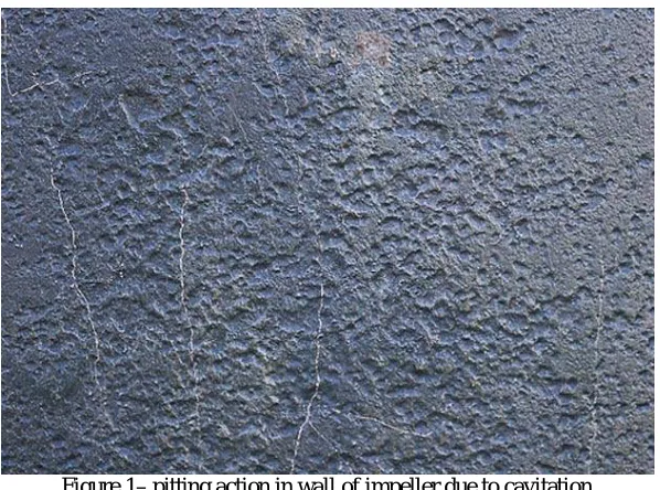
Figure 1– pitting action in wall of impeller due to cavitation
Figure 1 describes the pitting action in wall of impeller due to cavitation, dur to low vapour pressure water bubbles are formed, and when they get again high pressure through kinetic energy of impeller, it collapse and cause for cavitaion.
II. MATERIALS
Extensive work had been undertaken in the field of cavitation. This literature review however primarily covers cavitation in pumps. It includes cavitation detection parameters based on vibration analysis and other related parameters that of current interest. A brief theoretical background of the pump and cavitation subjects is included in the Appendix.
Young (1999) reported that Isaac Newton was the first person to record the observation of cavitation in the low pressure region formed between rolling surfaces. Wislicenus (1969) documented cavitation in connection with ship propellers which was observed by Reynolds long before it was observed in the trials of the destroyers Daring in 1894. This showed cavitation phenomena had been observed since long time ago.
ISSN(Online): 2319-8753 ISSN (Print): 2347-6710
I
nternational
J
ournal of
I
nnovative
R
esearch in
S
cience,
E
ngineering and
T
echnology
(An ISO 3297: 2007 Certified Organization)
Vol. 5, Issue 6, June 2016
companies. The area where cavitation was most likely to occur at the design flowrate was around the trailing face of the impeller vanes, immediately downstream of the inlet tips.
Knapp et al. (1970) studied the material damage caused by cavitation. Cavitation damage was often observed to occur in quite localized areas of the surface. This is quite true as cavitation and pitting can always found at the trailing edge of the impeller.
Safiah (2002) reported work on cavitation prediction in centrifugal pumps based on suction specific speed (Nss) limit values. In this work, the Nss was limited to 2.8 corresponds for the centrifugal pump to operate safely. This Nss limit value was set based on the findings of Pearsall (1972). There was however no consideration for other cavitation inception factors made in the simulation.
Medvitz et al. (2002) conducted performance analysis of cavitating flow in centrifugal pump using multiphase CFD. Characteristic performance trends associated with off-design flow and blade cavitation were observed. The rapid drop in head coefficient at low cavitation numbers (breakdown) was also captured for all the flow coefficients. Quasi-three-dimensional analysis was used to model a 7-blade pump impeller across a wide range of flow coefficients and cavitation numbers.
Ridha and Houcine (2003) reported a numerical approach to the prediction of cavitation in pumps. It was based on the flow monitoring through impellers. To calculate the internal flow, a software code PHOENICS based on CFD was used. The effects induced by volute on centrifugal pump’s cavitation phenomena were presented. The results obtained in the case of pumps with low specific speed and possible appearance of the classical cavitation into the blade-channels was also presented.
Nakai et al. (2003) reported work on cavitating flow in centrifugal impellers that were analysed and its stability was examined based on a closed cavity model. In the stability analysis, cavitation occurred with longer cavity was statically unstable in the impeller. The characteristics of the higher order modes corresponding to the rotating cavitation were found to change largely depending on the impeller geometry.
III. METHOD
Always calculate the NPSHa (Net Positive Suction Head available) from the system, and compare it with the NPSHr (Net Positive Suction Head required) by the pump. The NPSHa should always be one to two feet above the NPSHr of the pump to prevent cavitation.
The NPSHr is a function of the pump design and cannot be changed. The NPSHa is a function of the system parameters and can be changed. Included in the NPSHa is the atmospheric pressure, vapor pressure of the liquid being pumped, static height from the water level to the pump, and friction losses. The atmospheric pressure is related to the altitude. At higher altitudes, the atmospheric pressure is less and subsequently there is not as much energy available to push the liquid into the pump. The vapor pressure varies by the type of liquid and the temperature of the liquid. If the liquid is allowed to cool before the pump, it can often be pumped easier. Regarding the static height from the fluid level to the pump, it is often possible to move the pump closer to the fluid to increase the NPSHa. To reduce the friction losses, larger diameter pipes can often be employed to increase the NPSHa and thus prevent pump cavitation. If it is not possible to increase the NPSHa as described above, then the pump user should search for a larger pump or pump that runs at a lower speed with lower NPSHr.
Suction Head:
Based on the Energy Equation - the suction head in the fluid close to the impeller can be expressed as the sum of the static and the velocity head:
hs = ps/ γliquid + vs2 / 2 g
where
hs = suction head close to the impeller (m, in)
ps = static pressure in the fluid close to the impeller (Pa (N/m2), psi (lb/in2))
γliquid = specific weight of the liquid (N/m3, lb/ft3)
ISSN(Online): 2319-8753 ISSN (Print): 2347-6710
I
nternational
J
ournal of
I
nnovative
R
esearch in
S
cience,
E
ngineering and
T
echnology
(An ISO 3297: 2007 Certified Organization)
Vol. 5, Issue 6, June 2016
g = acceleration of gravity (9.81 m/s2, 386.1 in/s2)
We can not measure the suction head "close to the impeller". In practice we can measure the head at the pump suction flange. Be aware that - depending of the pump - the contribution to the NPSH value from the suction flange to the impeller can be substantial.
(Figure 2 – boiling point- pressure graph)
Above figure gives detail about vapour pressure at different temperature. This helps us to find the optimum pressure range so that we can provide minimum height or say suction head for avoiding cavitaion problem in various centrifugal pump.
Tables for saturation temperature, pressure and related suction head.
Temperature (0C)
Vapour Pressure (KN/m2)
Suction Head (m)
0 0.6 10.3
5 0.9 10.2
10 1.2 10.2
15 1.7 10.2
20 2.3 10.1
25 3.2 10.0
ISSN(Online): 2319-8753 ISSN (Print): 2347-6710
I
nternational
J
ournal of
I
nnovative
R
esearch in
S
cience,
E
ngineering and
T
echnology
(An ISO 3297: 2007 Certified Organization)
Vol. 5, Issue 6, June 2016
35 5.6 9.8
40 7.7 9.5
45 9.6 9.4
50 12.5 9.1
55 15.7 8.7
60 20 8.3
65 25 7.8
70 32.1 7.1
75 38.6 6.4
80 47.5 5.5
85 57.8 4.4
90 70 3.2
95 84.5 1.7
100 101.33 0.0
This table shows different suction head with respect to temperature and vapour pressure of liquid .Suction Head for Water as Affected by Temperature Suction head for water or max. elevation of a pump above a water surface as affected by the temperature of the pumping water is indicated in above table.
IV.EXPERIMENTAL SETUP AND ANALYSIS
An experimental rig was designed and built to induce cavitation in the centrifugal pump. This would enable the study of the behaviour of the cavitation as well as to formulate practicable diagnostic methods. An experiment rig was required where cavitation under controlled condition could be reproduced in the laboratory within a reasonable and affordable cost. The essential design requirement of this experimental rig was to induce cavitation such that vibration, sound, pressure and flow rate could be studied.
we take the datum through the centerline of the pump impeller inlet (eye). This difference is called the Net Positive Suction Head (NPSH), so that
NPSH =P1
ρg+ Vs
2g −
Pv ρg
Or
ISSN(Online): 2319-8753 ISSN (Print): 2347-6710
I
nternational
J
ournal of
I
nnovative
R
esearch in
S
cience,
E
ngineering and
T
echnology
(An ISO 3297: 2007 Certified Organization)
Vol. 5, Issue 6, June 2016
Here
P1/ρg = Pressure head at the inlet of pump
Vs2/2g = Velocity Head at suction pipe Pv/ρg = Vapour pressure head
There are two values of NPSH of interest. The first is the required NPSH, denoted (NPSH)R , that must be maintained
or exceeded so that cavitation will not occur and usually determined experimentally and provided by the manufacturer. The second value for NPSH of concern is the available NPSH, denoted (NPSH)A , which represents the head that
actually occurs for the particular piping system. This value can be determined experimentally, or calculated if the system parameters are known.
For proper pump operation (no cavitation) :
(NPSH)A > (NPSH)R
For obtaining cavitaion and its effect, we use Thoma’s cavitation constant
The cavitation constant: is the ratio of (NPSH)R to the total manomatric head (Hm) is known as the Thoma’s cavitation
constant (σ)
σ=(NPSH)R
Hm
If the value of σ is less than the critical value, σc then cavitaion will occur in the pump. The Cavitaion factor σ is a
function of specific speed, efficiency of the pump and number of vanes. The value of σc depends upon the specific
speed of the pump. i.e.
N =N√Q
Hm
The following empirical relation is used to obtain the value of σc
σc = 1.03 × 10⁻³ (Ns)4/3
Experiment No. – 1
For BFG, given that discharge of the pump, Q = 0.1667 m3/s Speed of Pump, N = 1250 RPM Manomatric Height Hm = 30 m
Atmospheric pressure head Ha = 10.193 m of water
Vapour pressure Head Hv = 0.305 m of water
Frictional head loss in suction pipe hfs = 0.2 m
Now specific speed of the pump will be given by
N =N√Q
Hm
Ns = 40 RPM
Now Critical value of σ is given by σc = 1.03 × 10⁻³ (Ns)4/3
ISSN(Online): 2319-8753 ISSN (Print): 2347-6710
I
nternational
J
ournal of
I
nnovative
R
esearch in
S
cience,
E
ngineering and
T
echnology
(An ISO 3297: 2007 Certified Organization)
Vol. 5, Issue 6, June 2016
Now NPSH is given by
σ=(NPSH)R
Hm
For minimum NPSH value of σ should be equals to its critical value Therefore
NPSH = σ × Hm
NPSH = 0.14523 × 30 = 4.3 m Also NPSH is gven by
NPSH = Ha – hs – hf – Hv
hs = 5.366 m.
So allowable suction head is 5.366 m for cavitation free operation.
Experiment No. – 2
For GPG, given that discharge of the pump, Q = 1.667 m3/s Speed of Pump, N = 700 RPM Manomatric Height Hm = 42 m
Atmospheric pressure head Ha = 10.29 m of water
Vapour pressure Head Hv = 0.224 m of water
Frictional head loss in suction pipe hfs = 1.42 m
Now specific speed of the pump will be given by
N =N√Q
Hm
Ns = 54.78 RPM
Now Critical value of σ is given by σc = 1.03 × 10⁻³ (Ns)4/3
σc = 0.2142
Now NPSH is given by
σ=(NPSH)R
Hm
For minimum NPSH value of σ should be equals to its critical value
Therefore
NPSH = σ × Hm
NPSH = 0.2142 × 42 = 9 m
Also NPSH is gven by
NPSH = Ha – hs – hf – Hv
ISSN(Online): 2319-8753 ISSN (Print): 2347-6710
I
nternational
J
ournal of
I
nnovative
R
esearch in
S
cience,
E
ngineering and
T
echnology
(An ISO 3297: 2007 Certified Organization)
Vol. 5, Issue 6, June 2016
Negative value of suction head shows that there is no need to change the height of suction. i.e. its there are no problem of cavitation in this pump.
V. FUTURERECOMMENDATIONSFORPROJECT
Additional pump operating parameters of the centrifugal pump could be considered in an extension of the current study. These could include parameters such as the power input of the centrifugal pump, the bubble size, the bubble collapse size, to be measured. This was not possible due to limited financial funding of the current work. The experimental rig facilities such as high speed camera shall be made available for enhanced photographic visualization. The application of the best analysis method in cavitation should be investigated, which could be a more sensitive tool. The comparison of fourier analysis and envelope analysis in term of cavitation severity should be investigated further too. In the study of the flow dynamics, Computational Fluid Dynamic (CFD) could be used to model the flow and predict the cavitation inception. In term of the sound measurement, With the available pressure reading, the value of NPSHa, TDH, cavitation number could be calculated and documented for future comparison. Historical FFT spectrums, pressure and flow rate results shall be trended for monitoring purpose. It could be useful to detect any abnormal operation. The running speed of the motor shall be varied to avoid the pump operating at the cavitation condition. This indeed would affect the delivery head and flow and further study is required. FFT of the sound signal could be made available for the cavitation detection. With the testing facilities available, different type of centrifugal pump with different suction specific number could be tested. The prognostic study of the cavitation damage until the pump fails totally is a fruitful topic as well.
VI.CONCLUSION
we found that there are serious problem in most of the pumps, which can only reduced by providing them minimum net positive suction head as recommended in previous section.
REFERENCES
1. Bloch, H.P. and Budris, A.R.. Pump User’s Handbook Life Extension. Georgia: The Fairmont Press Inc. (2005) 2. Brennen C.E. Cavitation and Bubble Dynamics. USA: Oxford University Press. (1995).
3. Chen, Y.M. and Mongis, J. (2005). Cavitation Wear in Plain Bearing: Case Study. Sciences. 195-201. 2005
4. Cudina, M. Detection of Cavitation Phenomenon in a Centrifugal Pump Using Audible Sound. Mechanical Systems and Signal Processing. 2003. Vol 17(6): 1335-1347. (2003).
5. Escaler, X., Egusquiza, E., Farhat, M., Avellan, F. and Coussirat, M. (2004). Detection of Cavitation in Hydraulics Turbine. Journal of Mechanical Systems and Signal Processing. 11 August 2004.
6. Friedrichs, J., Kosyna, G. Rotating Cavitation in a Centrifugal Pump Impeller of Low Specific Speed. Journal of Fluids Engineering. 2002. Vol 124: 356-362 (2002).
7. Gandhi, B.K., Chauhan, D.P.S. and Panday, M.M. Diagnosing Cavitation in Centrifugal Pumps Using Noise and Vibration Signatures. 2nd World Engineering Congress.. Malaysia: Universiti Putra Malaysia Press. 325-330. 22 – 25 July, 2002
8. Jaksch, I.. Fault Diagnosis of Three-Phase Induction Motors Using Envelope Analysis. Symposium on Diagnostics for Electric Machines, Power Electronics and Drives. Atlanta, USA.. IEEE, 289-293. 24-26 August 2003
9. Jarrell, D.B. (2003). Analysis of Vibration and Acoustic Data for Ice Harbor Dam Auxiliary Water Supply Pumps. Submitted to the U.S Army Core of Engineers. September 2003.
10. Jensen, J., Dayton, K. Detecting Cavitation in Centrifugal Pumps – Experimental Results of the Pump Laboratory. Orbit Second Quarter 2000. 26-30. (2000).
11. Kaye, M, Cavitation Monitoring of Hydraulic Machines by Vibration Analysis. Swiss Federal Institute of Technology. PhD. Thesis. . (1999). 12. Nagahara, T., Sato, T. and Okamura, T. Effect of the Submerged Vortex Cavitation Occurred in Pump Suction Intake on Hydraulic Forces of
Mixed Flow Pump Impeller. Fourth International Symposium on Cavitation. Japan. (2001).
13. Nakai, H., Horiguchi, H., Nakano, M. and Tsujimoto, Y. (2003). Cavitating Flows in Centrifugal Impellers and Their Stability Analysis. Fifth International Symposium on Cavitation. Osaka, Japan. 1-4, November 2003.
14. Tan, C. Z. and Leong, M. S. An Experimental Study on the Detection of Cavitation in a Centrifugal Pump Using FFT Vibration Analysis. 11th Asia- Pacific Vibration Conference. November 23-25, 2005.
15. Thoma, D. Die Kavitation bei Wasser-Turbinen. Berlin :VDI Verlag. 65-74. (1926)
ISSN(Online): 2319-8753 ISSN (Print): 2347-6710
I
nternational
J
ournal of
I
nnovative
R
esearch in
S
cience,
E
ngineering and
T
echnology
(An ISO 3297: 2007 Certified Organization)
Vol. 5, Issue 6, June 2016
17. Wislicenus, G.F. Remarks on the History of Cavitation as an Engineering Problem. Proceedings of the ASME Fluids Engineering and Applied Mechanics Conference. Illinois.. New York: The American Society of Mechanical Engineers, 10-14. June 16 – 18, 1969
18. Yagi, Y., Murase, M., Sato, K. and Saito, Y. (2003). Preliminary Study of Detecting the Occurrence of Cavitation and Evaluating Its Influence by an Accelerometer Mounted on a Pipe. Fifth International Symposium on Cavitation. Osaka, Japan. 1-4, November 2003.