ABSTRACT
GUPTA, SHALINI. On-chip Assembly of Electrically Functional Structures from Biological and Colloidal Particles. (Under the direction of Orlin D. Velev and Peter K. Kilpatrick.)
We study the assembly of electrically functional and miniaturized biosensors from colloidal systems ranging from synthetic organic/inorganic micro- and nanoparticles to naturally existing live cells. The unique combination of highly specific biological interactions and different assembly schemes – 1) controlled manipulation in externally applied electric fields, and 2) free diffusion in bulk suspensions are investigated as a versatile tool for fabricating simple, rapid and inexpensive sensing devices that can potentially be interfaced with electrical circuits on a chip. For each system, a detailed modeling is carried out with the aim to acquire fundamental understanding of the operating parameters involved in the assembly process.
nanoparticles makes a conductive patch on the substrate, these assays could allow direct interfacing to on-chip electrodes for electrical readout of the results.
The co-assembly of live cells and synthetic microparticles on electrically controlled chips is demonstrated as a simple and facile route to making novel biocomposite materials, in which the biological functionality of the cells is augmented by the physical functionality of the particles. One-dimensional chains and planar membranes from live cells and colloidal particles are assembled by dielectrophoresis. The experimental results and numerical simulations of the assembly dynamics indicate that the electric field draws the particles into the interstitial junctions between the cells, where the field strength is greatest. This allows using the particles as binding elements. Permanent cell-particle chains and membranes are assembled dielectrophoretically by biospecifically binding yeast and mouse fibroblast cells with lectin-conjugated magnetic microparticles. Such biomagnetic cell-particle assemblies may find application in sensors, microassays, microsurgery, or as responsive biomaterials.
On-chip Assembly of Electrically Functional Structures from
Biological and Colloidal Particles
by
Shalini Gupta
A dissertation submitted to the Graduate Faculty of North Carolina State University
in partial fulfillment of the requirements for the Degree of
Doctor of Philosophy
Chemical Engineering
Raleigh, North Carolina 2007
APPROVED BY:
_______________________ _______________________ Saad Khan Jason Haugh
DEDICATION
this dissertation is dedicated to my parents
Vijay and Bhagwan Das Gupta
and to my husband Ashish
BIOGRAPHY
Shalini Gupta was born on March 5 1980 in the city of Roorkee nestled on the banks of river
Ganges in the north Indian state of Uttarakhand. She was, however, raised in Kanpur
(formerly known as Cawnpore) - a populous and historic town that not only stands proud as
one of north India’s major centers for leather and textile industries but is also host to several
premiere educational institutions including the famous Indian Institute of Technology (I.I.T.).
The academically charged milieu of I.I.T., where her father is a professor, played a crucial
role in kindling in Shalini a curiosity for science and engineering at an early age.
Consequently in 1998, she secured a rank in the All India Joint Entrance Examination
(AI-JEE). This selection and a disclosed desire to experience life away from home lead to the
subsequent choice of studying Chemical Engineering at the Institute of Technology–BHU,
Varanasi, India.
On one hot afternoon in the year 2000, she got her first glimpse into the wonders of
nanotechnology during a class presentation made by her fellow undergraduate chemical
engineer. The fascination for the word nano culminated into her joining the PhD program at
North Carolina State University immediately after receiving a B.Tech. degree in Chemical
Engineering in 2002. Since then, she has been pursuing graduate level research in the field of
colloid science and nanoscale surface interactions under the guidance of Dr. Orlin Velev and
ACKNOWLEDGEMENTS
I like to express profound gratitude to my dissertation advisor Dr. Orlin Velev who has been
an exceptional mentor and a constant source of inspiration for me; an exceptional mentor
because he has always steered me in the right direction, afforded me the freedom of thought
and flexibility of working at odd hours, and always found time from his busy schedule to
discuss my problems. He has been a constant source of inspiration because of his relentless
drive and enthusiasm for science (I like referring to him as the self-propelling di-u-de ☺). I
have always admired him for his originality of thought in research, work ethic and most of all
for his amazing memory! Dr. Velev, I thank you for all the help and valuable inputs you have
given me during the course of my PhD and I wish you continued success in all future
endeavors.
I respectfully acknowledge Dr. Peter Kilpatrick for being an excellent dissertation
co-advisor. He has always motivated me to put my best effort under his able guidance. I thank
Professors Saad Khan and Jason Haugh for serving on my dissertation committee. I
appreciate the help received from Dr. Rajendra Bhat for the preparation of the APTES gold
gradients. I am also grateful to Michael Weiger for patiently providing the fibroblast cells. I
like to thank Professors Gregory Parsons, Jason Haugh and Peter Fedkiw for allowing me the
generous use of AFM, TIRF and EIS, respectively. Fruitful discussions with Erik Santiso on
numerical modeling are also highly valued. The administrative staff of the Chemical and
Biomolecular Engineering department cannot be thanked enough for their unfailing
dedication to simplifying the life of every graduate student. You guys are doing a marvelous
has looked after me like a doting mother. I am also thankful to the resourceful help received
from Kit Yeung in constructing and repairing devices during the course of my graduate study.
I have been extremely fortunate to have shared the common office and lab space with
my wonderful colleagues in the Velev research group. I am thankful to the former group
members, Dr. Ketan Bhatt and Dr. Brian Prevo, for exposing me to the subtle realities of
operating in a lab setting. I also benefited immensely from the highly developed experimental
skills of our past post doc, Dr. Rossitza Alargova. I thoroughly enjoyed the opportunity of
working closely with two zealous undergraduates, Sabil Huda and Cheng Lu, who have now
graduated. In the office, I cherish the time spent with my colleagues Vinayak, Suk Tae,
Sumit, Sejong, Lindsey, Olivier, Liz and Jairus, especially during lunch hour when we shared
multi-ethnic food and chatted about myriads of topics covering cultural, historical and
political issues. Thank you all for providing the helpful feedback during the numerous
practice presentations. Special thanks to Vinayak for being an occasional critic (and a
dependable gossip buddy☺). Outside the Velev group, I frequently miss the company of my
classmates (batch of 2002) with whom I had the fun opportunity to share TA room 9 in
Riddick. I extend my sincere thanks to Dr. Srinivas Siripurapu for introducing me to this
awe-inspiring department and for also helping me during my initial days in the U.S.
Over the last 5 years of my stay in Raleigh, I have made a few very good friends -
Chetna and Itisha being the closest to my heart. Chetna and Itisha, I can never forget our
bonding sessions that inevitably stretched into night-long “spiritual” conversations. You two
have redefined the meaning of friendship for me and I can only hope to become half the
Prashant, Vinit, Abheek and Pushkin. Time spent with you guys playing pranks, literature,
volleyball and mafia have been my most joyous moments in the U.S. I will miss you guys
terribly but I promise I will always keep in touch.
I cannot express in words my appreciation for my parents and for everything that they
have done for me – from waking up with me through the middle of the night to letting me
make my own decisions in life. Papa and mummy, I am indebted to your love and sacrifices.
I thank my elder sister Sonia and Manoj jiaji from the bottom of my heart for just being there
when I needed them most. My kid brother Gaurav deserves special thanks for teaching me to
appreciate the world beyond engineering.
My highest gratitude is reserved for my husband Ashish who has been my pillar of
strength though the course of my graduate studies. Thank you for always believing in me and
for patiently putting up with my dreadful frustrations!
Last but not least, I would like to thank the funding resources for financially
TABLE OF CONTENTS
List of Tables ……….... List of Figures ………... 1. Introduction and Dissertation Goals ………..
1.1 Introduction ……….... 1.2 Methods and Strategies for Assembly of Structures from Micro and Nanoparticles ……….
1.2.1 One-Dimensional Structures ………...
1.2.2 Two-Dimensional Films and Crystals ………... 1.2.3 Three-Dimensional Materials ………... 1.2.4 Supraparticles, Colloidosomes and Colloidal Molecules ………...
1.3 Advanced Materials with Biological Functionality ……….... 1.4 Layout of this Dissertation ………... 1.5 References ………....
2. Silver Enhanced Gold Nanoparticle Immunoassays ………..
2.1 Abstract ……….... 2.2 Introduction ………..
2.2.1 Kinetics of Analyte Adsorption ………..
2.3 Materials and Methods ……….. ..
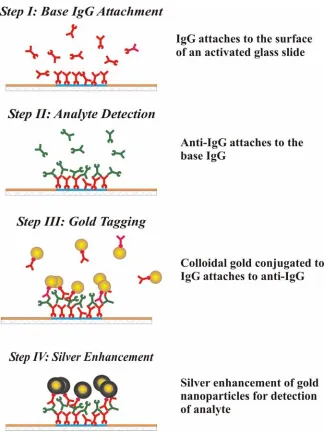
2.3.1 Immunoassay Principles ………... 2.3.2 Antibodies and Reagents ………... 2.3.3 Substrate Preparation and Experimental Setup ………....
2.3.4 Immunoassay Protocol ………... 2.3.5 Optical Densitometry Analysis ……….. 2.3.6 Formation of Gold Gradients via APTES Monolayer
Self-Assembly ………...
2.4 Results and Discussion ………...
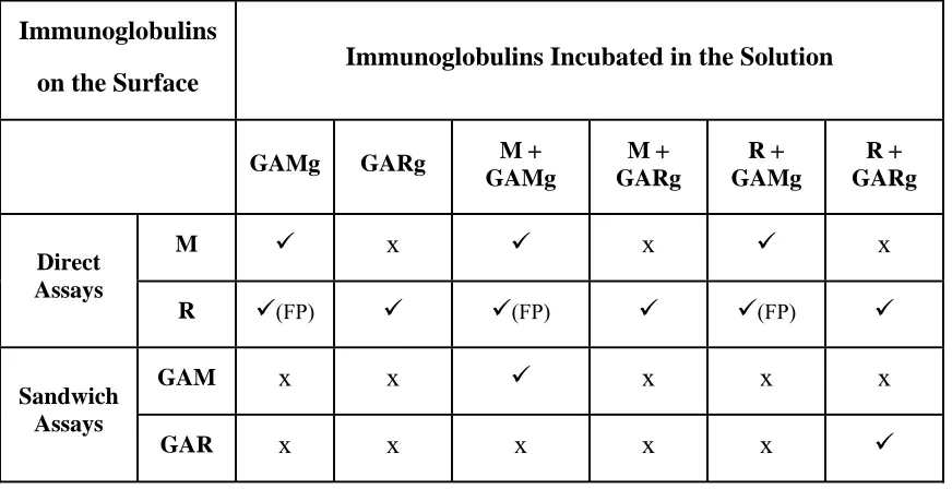
2.4.1 Assay Selectivity ………....
2.4.2 Estimation of Thiele Modulus for the Kinetic Model Based on the System Parameters ………... 2.4.3 Relationship between Optical Darkness Ratio (ODR) and Surface
Coverage (Γ) ………... 2.4.4 Assay Sensitivity: Effect of Major Parameters ………... 2.4.5 Formulation of General Procedure for Assay Optimization ……...
2.5 Conclusions ………... 2.6 Directions for Future Research ………... 2.7 Acknowledgements ………. 2.8 References ………...
3. Novel Structures from Cells and Particles using Dielectrophoresis …..
3.1 Abstract ……….... 3.2 Introduction ……….. 3.3 Experimental Section ………...
3.3.1 Materials and Sample Preparation ………... 3.3.2 Setup ……….. 3.3.3 Optical Microscopy and Image Analysis ………... 3.3.4 Cell Viability Tests ………....
3.4 Results and Discussion ………...
3.4.1 Cell Viability under the Influence of Electric Fields ………. 3.4.2 Effect of Operating Parameters on the Assembly of Cell Chains …. 3.4.3 Numerical Simulation of Dielectrophoretic Assembly ……….. 3.4.4 Dielectrophoretic Co-Assembly of Cell-Particle Binary Systems... 3.4.5 Cell Chains made Permanent by Functionalized Microparticles
and Ligands ………... 3.4.6 Cell 2D Arrays ………...
3.5 Conclusions ………. 3.6 Acknowledgements ………. 3.7 References ………...
4. Latex Agglutination Detection by Electrochemical Impedance ……...
4.1 Abstract ……….. 4.2 Introduction ………. 4.3 Experimental Procedure ………...
4.3.1 Materials ………... 4.3.2 Sample Preparation ………... 4.3.3 Experimental Apparatus ………... 4.3.4 Methods ………. 4.3.5 LATs by TIRF Microscopy ………....
4.4 Results and Discussion ………...
4.4.1 Effect of Operating Parameters ……….... 4.4.2 Electrochemical Impedance Measurements of Latex
Agglutination Tests ……….... 4.4.3 EIS-Agglutination based Digital Immunosensors ……….
4.5 Conclusions ………. 4.6 Acknowledgements ………. 4.7 References ………...
5. Summary and Outlook ………..
5.1 Summary ……….. 5.2 Outlook: Rocky Road from Science to Engineering ………... 5.3 References ………....
Appendix A: Protocols Used for Conjugating Proteins to Colloidal Particles ………..
A.1 Chemical Conjugation of Concanavalin A Lectin to 1.0 µm Fluorescent Aldehyde/Sulfate Latex Microspheres ………....
A.1.1 Reagents ……….... A.1.2 Preparation of Latex Suspension ………..
Lectin ………....
A.2 Chemical Conjugation of Concanavalin A Lectin to 1.8 µm
Amine-Terminated Magnetic Iron Oxide Particles ……….
A.2.1 Reagents ……….... A.2.2 Activation of Magnetic Particles ………... A.2.3 Functionalization of Magnetic Microspheres with
Concanavalin A Lectin ………. A.2.4 Washing and Dilution of the Conjugated Magnetic Particles …….. A.2.5 Coupling Efficiency ………...
A.3 Physical Adsorption of Fibronectin to 1.0 µm Sulfate-Stabilized Latex Microspheres ………... A.4 References ………...
Appendix B: Polarizability Calculations using Multi-Shell Models ……...
B.1 Multi-shell Model for Yeast Cells ………... B.2 Multi-shell Model for Latex Particles ………... B.3 References ………...
168
169
169 169
170 170 171
171 174
175
LIST OF TABLES
Table 1.1 Table 2.1 Table 2.2 Table 2.3 Table 3.1 Table 3.2 Table 3.3 Table 4.1 Table A.1 Table B.1 Table B.2Strategies and limitations for assembly of colloidal structures…..
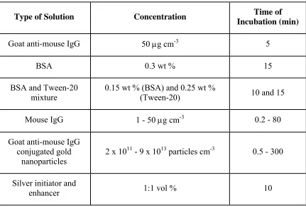
Range of concentrations and incubation times of all solutions used in developing the immunoassays. All solutions except the ones for silver enhancement were prepared in 10 mM PBS at pH 7.4………...
Selectivity control table. The symbols represent enhancement ( ), no enhancement (x) and false positive ( (FP))………..
Smallest incubation times required to reach saturation for different concentrations of analyte and nanoparticle conjugates...
A list of physical parameters used for the calculation of the characteristic relaxation frequency of yeast cells………...
Force calculations for interactions between cells. Comparison between numerical and analytical values obtained for dipolar forces between yeast cells at two different positions……….
A list summarizing the binding and control experiments performed on yeast and NIH/3T3 mouse fibroblast cells. The applied AC fields are of strengths 5 - 17 V mm-1 and frequencies 50 Hz – 10 kHz. The concentrations of cells are between 0.01 - 0.2 % w/v………...
A list of latex-IgG concentrations used in the experiments. The values on the right show the optimal antigen concentrations needed for their agglutination……….
A list of reagents used for conjugating Concanavalin A lectin to amine-terminated magnetic iron oxide particles………...
Numerical parameters for calculating effective polarizability of yeast (S. cerevisiae) cells.1,2………...
Numerical parameters for calculating the effective polarizability of 1 µm latex particles. The values of these parameters were taken from Ref. [2] and from the information data sheet provided by the vendor, Interfacial Dynamics Corp. (OR)……....
LIST OF FIGURES
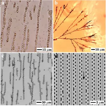
Figure 1.1 Figure 1.2 Figure 1.3 Figure 2.1 Figure 2.2 Figure 2.3Examples of one-dimensional structures. Colloidal assembly in external AC electric fields: (a) Permanent chains from live yeast
cells and lectin functionalized microparticles,55 (b) Self-repairing
microwires from gold nanoparticles,60,61 and (c) Zigzag chains
from anisotropic microspheres;53 (d) Zigzag chains formed via
templated assembly.39………..
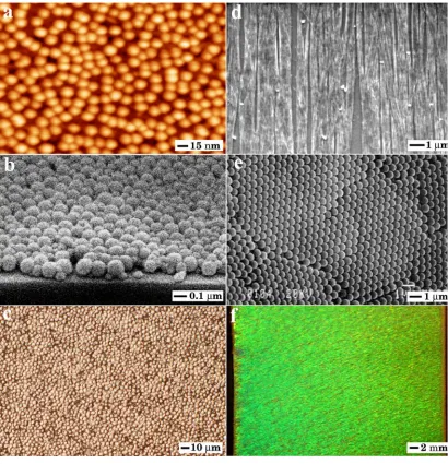
Examples of two-dimensional assemblies. Structures fabricated via convective assembly: (a) Electrostatic deposition of gold
nanoparticles on a self-assembled monolayer (SAM) of APTES,69 (b) Unordered assembly from a binary mixture of
particles,83 (
c) Organization of live yeast cells into arrays,84 (d)
Assembly of Tobacco Mosaic Virus (TMV) into arrays,82 and (e)
Highly ordered colloidal crystal.81 (f) 2D crystallization of latex
microspheres using AC electric field.59………... Examples of self-contained particles. (a) Particle collection
around emulsion droplets;118 (b) Semi-permeable
colloidosomes;123 (c) Colloidal molecules;126 (d)
Microrod-stabilized “hairy” colloidosomes;124 (e) Anisotropic “eyeball”
supraparticles;122 (f) Doughnut-like assemblies.121………..
Schematic of the sandwich immunoassay depicting the sequential steps followed during the experiment. The figure is not drawn to scale………..
(a) Experimental setup for performing the immunoassay. (b, c)
Examples of two silver-enhanced spots. The spot in (b) was obtained with a mouse IgG concentration of 30 µg cm-3 incubated for 30 min with gold nanoparticle suspension, and (c) was obtained with a mouse IgG concentration of 1 µg cm-3 incubated for 45 min with gold nanoparticle suspension. All other conditions were maintained constant………..
Figure 2.4 Figure 2.5 Figure 2.6 Figure 2.7 Figure 2.8 Figure 2.9
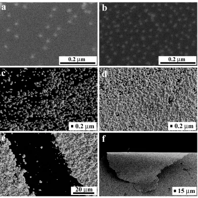
SEM images of samples containing ~12-nm gold particles deposited on an APTES-functionalized silicon wafer. (a, c)
Areas of low coverage before and after silver enhancement. (b, d) Areas of high coverage before and after silver enhancement.
(e, f) Silver layer deposits imaged at high and low magnification..
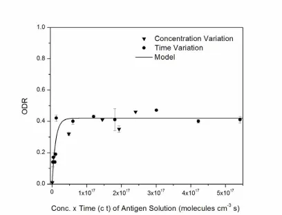
Optical darkness of silver-enhanced spots as a function of the product of antigen concentration in solution and incubation time ( ct ). (▼) various concentrations of mouse IgG antigen incubated for 20 min each and ( ) 50 µg cm-3 mouse IgG solution incubated for varying time intervals. The concentration and incubation time of gold nanoparticle suspension were 6.8 × 10¹³ particles cm-3 and 45 min in every experiment. The adsorption rate constant of the fitted curve is (1.0 ± 0.2) × 10-16 cm3 molecules-1 s-1………... Optical darkness of silver-enhanced spots vs concentration of gold nanoparticle suspension incubated for 45 min. The concentration and incubation time of M IgG antigens were 50 µg cm-3 and 20 min in every experiment. The adsorption rate constant of the fitted curve is (2.4 ± 0.6) × 10-17 cm3 molecules
-1 s-1………...
Optical darkness of silver-enhanced spots vs incubation time of 6.8 × 10¹³ particles cm-3 concentrated gold nanoparticle suspension. The plots are for different concentrations of M IgG antigens: (a) 50, (b) 30, (c) 20, and (d) 5 µg cm-3. The incubation
time of antigens was 20 min in every experiment. The adsorption rate constants of the fitted curves are as follows: (a) (2.4 ± 0.6) × 10-17 and (b-d) (2.2 ± 0.5) × 10-16 cm3 molecules-1 s-1………
SEM images of silver-enhanced immunoassays after (a) 1.5 and
(b) 10 min of incubation with gold nanoparticle suspension. The
concentration and incubation time of M IgG antigens were 30 µg cm-3 and 20 min in both experiments. The scale bar represents 30
µm………...
I-V measurements of silver enhanced spots: (a) Schematic
illustration of the experimental setup used. The sweep voltage was 0 to 10 V. (b) Silver enhanced spot on which the
measurements were performed. The concentration and incubation time of the different reagents used were as follows: (i) M IgG antigens - 50 µg cm-3 and 20 min, (ii) Gold nanoparticles: 1.36 ×
56
57
58
59
Figure 3.1 Figure 3.2 Figure 3.3 Figure 3.4 Figure 3.5 Figure 3.6
incubation followed by washing and incubation with new silver solution for another 10 min. (c) Current-voltage (I-V) data taken
for varying distances between the electrode probes. The results show a strong ohmic dependence in all cases. (d) The resistance
of the spot has a peak at some intermediate probe distance due to the coffee ring effect………....
Schematic of the types of cell-cell and cell-particle assemblies formed using dielectrophoresis in AC electric fields………...
Schematic of the chips used for the dielectrophoretic assembly of live cells: (a) Parallel coplanar gold electrodes for making 1D
chains and, (b) Orthogonally arranged four-point brass electrodes
for fabricating uniform 2D arrays………....
Chains assembled from live cells using AC electric fields. (a)
Yeast (S. cerevisiae) cell chains under 15 V mm-1 and 50 Hz
electric field. Inset: The viability of the cells remains preserved in the electric field after 2 h as indicated by the gutted appearance of the cell interior; (b) NIH/3T3 mouse fibroblast
cells under 10 V mm-1 and 10 kHz electric field. Inset: Magnified view of the black rectangle shown in (b). The blue color indicates a dead cell. Most cells stay alive during the assembly process for up to 1 h. [Please note that there is no detectable diff- erence in the responses of the dead and the live cells at the low frequencies used]……….
Effect of the applied AC electric field on the cell chain length; longer chains are formed at higher voltages and lower frequencies. Each data point is an average of count from 10 different images………...
Effect of pH on the dielectrophoretic assembly of cell chains determined as a function of frequency. The electric field intensity
is 10 V mm-1………....
Snapshots of the electrostatic simulation at various stages of cell assembly compared with the actual experimental images. The AC electric field is 13 V mm-1 and 100 Hz in both cases. (a)
Boundary conditions and the geometry specified in the model. (b - d) Time-lapsed simulation of the field intensity distributions
and cell re-arrangement using FEMLAB are color coded. The higher polarizability of the cells leads to attraction by positive dielectrophoresis. (e-g) Actual experimental images capturing the
Figure 3.7
Figure 3.8
Figure 3.9
Figure 3.10
Figure 3.11
dynamics of cell alignment in AC field………...
Morphology diagram showing the interaction-induced phase separation of yeast cells and 5 µm sulfate-stabilized latex spheres as a function of field strength and frequency. The different regions in the phase diagram indicate: (a) Homogeneous
distribution of cells and latex particles through the entire length of the chains, (b) Weaker interaction of cells with neighboring
cells and latex particles leading to increased proportion of latex particles in the chains, and (c) Complete phase separation of the
cells resulting in latex particle-only chains………..
Alternating linear composite clusters of yeast cells (0.2 % w/v) and 1 µm green fluorescent latex particles (0.025 % w/v) assembled at 15 V mm-1 and 200 Hz AC electric field. (a)
Optical micrograph taken after the field was applied for 45 mins. (b) Complementary image of (a) acquired using fluorescence
microscopy. The green fluorescent stripes indicate the relative position of the latex microparticles between the cells……….
Time-lapsed images of the co-assembly dynamics of a cell-particle system at 100 Hz. (a) Specifications of the system
geometry and boundary conditions used in the model. (b - d)
Three snapshots of the dynamic simulation, where the field intensity distribution is color coded. The higher polarizability of the cells leads to attraction and chaining. The simulation illustrat- es how one of the particles is captured in the higher intensity area between the cells in the “chain”. This process is observed experimentally (e - g) and is used to bind the structure…………...
Permanent cell chains using functionalized binder particles. (a)
Yeast cells with 1.8 µm amine-terminated iron-oxide particles. (b) Yeast cells with 1.0 µm lectin-coated fluorescent latex
particles. (c) Yeast cells with 0.95 µm lectin-coated magnetic
particles. (d) Mouse fibroblast cells with 0.95 µm lectin-coated
magnetic particles. Insets show chain rotation using an external magnet………..
Permanent binding of yeast cell chains using (a) poly(dimethyl
aminoethyl methacrylate) (PDMAEMA), (b) Concanavalin-A
lectin, (c) D-Mannose, and (d) Both Concanavalin-A lectin and
Figure 3.13 Figure 3.14 Figure 4.1 Figure 4.2 Figure 4.3 Figure 4.4
bling uniform 2D cell arrays. (a) No close-packed 2D yeast cell
array was obtained using two parallel coplanar electrodes; (b)
Organization of yeast cells into close-packed 2D arrays using the 4-point electrode setup. The field was applied for 30 min; (c)
Random deposition of yeast cells that were freely sedimented under gravity-only force (no electric field) for 30 min…………....
Micrographs of permanent cell membranes bound together by Con-A functionalized microparticles. (a) Large magnetic yeast
cell membrane at low microscope magnification; note that the membrane is only one cell layer thick. (b) SEM image of a
closely-packed fixed yeast membrane. (c) NIH/3T3 mouse
fibroblast membrane………....
Magnetic manipulation of responsive cell membranes. (a)
Folding of a large magnetic yeast cell membrane by an external magnetic field. (b) Extraction and transport of a yeast cell
membrane through thin Teflon tube using an external magnet. Inset: Arrow points to the actual position of the membrane in the tubing attached to the chip used in the experiments………....
Schematics of the principle of latex agglutination tests (LATs) and the various methods used for detecting their results………….
Experimental setup (not drawn to scale). Top view: Design of
glass chip with the micropatterned interdigitated electrodes. Electrodes 1 and 3 are energized against electrodes 2 and 4. Dotted line marks the inner edge of the microfluidic chamber.
Side view: Sample is loaded into the microfluidic chamber
encapsulating the interdigitated electrodes. The inlet and outlet ports are sealed to avoid evaporation. Sedimentation of particles is measured using electrochemical impedance spectroscopy (EIS).
Fitting of the impedance data to an equivalent circuit model: (a)
DI water and (b) physiological media. Constant phase elements
QDL and QDI represent the non-ideal capacitive behavior of the
electric double layer and dielectric, respectively. Rsol and Rsurf
represent the resistances of the solution and surface, in that order..
Impedance spectra obtained with DI water and physiological buffer medium. The significant drift in impedance below 0.1 MHz frequency results possibly due to the swelling of the adhesive polymer or its slow diffusion into the flow chamber…....
Figure 4.5 Figure 4.6 Figure 4.7 Figure 4.8 Figure 4.9 Figure 4.10 Figure 4.11
Effect of (a) sedimentation time and (b) particle concentration on
the impedance spectra at 1 MHz. The results in (a) are reported for 1 µm sized latex-IgG particles. The results in (b) are shown for 1 and 2 µm latex after the particles have sedimented completely in 90 and 30 min, respectively. Characteristic local peaks in impedance are registered near the monolayer concentrations of the two particles………..
Effect of sedimentation time on the impedance spectra at 1 MHz for (a) 1 µm and (b) 2 µm sized latex particles. The pattern of
impedance change is similar to that of latex-IgG particles………..
Time dependent impedance response fitted to the PBS model as 3.25 % w/v latex-IgG particles sediment and accumulate on the electrode surface. (a) Equivalent circuit model. (b) Evolution of
the angles and capacitive parts of the constant phase elements for the electric double layer and dielectric. (c) Evolution of the
solution and surface resistances. The fitting is performed for impedance data between 1 Hz – 1 MHz………...
Effect of particle size on the impedance spectra at 1 MHz. The readings are taken for 1, 2, 4 and 8.7 µm latex after the particles have sedimented completely in 90, 30, 10 and 5 min, in that order. The concentration of latex particles is 0.44 % w/v in all cases. Note that 0.44 % w/v concentration corresponds to the monolayer coverage of 1 µm latex particles………...
Time-lapsed optical microscopy images showing how the agglutination of 3.25 % w/v latex-IgG particles with 1 µg mL-1 antigen proceeds in (a) 1 min, (b) 30 min, (c) 60 min, and (d) 90
min. These images are acquired after diluting the sample 100x and dispensing 10 µL of it on a glass slide under a glass cover slip………...
The dynamic change in impedance at 1 MHz before and after antigen (1 µg mL-1) is added to the latex-IgG suspension (3.25 % w/v). Addition of antigen alone has little effect on the impedance at this frequency………...
Detection of latex agglutination results using Total Internal Reflection Fluorescence (TIRF) microscopy. (a) Schematics of
the principle of TIRF microscopy. (b) A timed comparison of the
fluorescence intensity as latex-IgG particles (0.06 % w/v)
Figure 4.12
Figure 4.13
Figure 5.1
Figure B.1
Figure B.2
The intensity gets saturated much faster without antigens. (c)
Average fluorescence intensity of the sedimenting particles plotted as a function of time……….
Qualitative detection of antigen by the second derivative method. (a) Impedance spectra measured between 0.1 – 1 MHz as the
latex-IgGs (3.25 % w/v) sediment in the presence and absence of antigens during 90 min. (b) Second derivative of the impedance
signal changes from negative to positive in the presence of antigens - ideal behavior for a biosensor. The qualitative response of the sensor is registered equally well at 10 and 90 min. [Note: scales different on Y-axes]………..
Performance of the impedance based immunosensor at 10 min for three different concentrations of latex-IgG suspensions: (a)
2.05 % w/v, (b) 1.25 % w/v, and (c) 0.06 % w/v. The
corresponding antigen concentrations are 0.631, 0.385, and 0.018
µg mL-1, respectively. Immunosensor works effectively only for high particle concentrations………...……….
A hypothetical evaluation of the value added for different types of colloidal assemblies vs. the cost of their fabrication. Materials positioned to the left and the top side of the graph are more likely to find practical applications. The likely positions of simple and complex synthetic particles and microelectronic chips are shown for comparison. We demonstrate how high value added bioelectronic materials can be assembled on a chip using directed assembly of biological and colloidal particles……….
(a) Multi-shell model for the polarizability of yeast cell. (b)
Simplified model of yeast cell with effective polarizability equivalent to the multi-shell type structure in (a)………....
Models of latex microspheres in aqueous media: (a) Thin
conductive counter-ionic layer surrounding the latex microsphere.
(b) Simplified structure with effective polarizability equivalent to
the shell type structure in (a)………....
Chapter 1
Introduction and Dissertation Goals*
__________________________
1.1 Introduction
The organization of matter in nanomaterials and nanodevices can be accomplished by
top-down miniaturization techniques or bottom-up methods typically based on self-assembly or
directed assembly.1,2 Colloid micro and nanoparticles are one of the most widely used classes of objects in bottom-up assembly. A large research effort is directed to the fabrication of
materials from highly organized particles with advanced functionality and specific
applications in areas such as photonics, electronics, sensing, and catalysis.3-15 We begin this Dissertation with an overview of some of the basic types of particle assemblies reported in
the literature and the strategies for their fabrication, classified on the basis of their
dimensionality. Various applications of the structures assembled from particles are surveyed.
1.2 Methods and Strategies for Assembly of Structures from Micro and Nanoparticles
A convenient way to classify the majority of the colloidal assemblies could be based on their
dimensionality and degree of ordering - three, two, one-dimensional, or independent
aggregates. In order to evaluate the ease and precision of the controlled fabrication of such
materials, we also need to consider in each case the method by which a certain structure is
assembled. The assembly can be accomplished by an extensive array of techniques using
various physical mechanisms. A survey of a few major groups of methods that have found
use in the controlled assembly of particles into materials with well-organized and defined
microstructure is presented in Table 1.1. The goal of all these techniques is to collect the
particles, organize them and bind the structure formed into a permanent material. The
directed by capillarity19-22 or driven by external fields.23-34 The organization can be a result of packing the particles to initiate crystallization,35-37 or templating them on surfaces and objects.38-41 The binding can be achieved with methods as simple as adding electrolytes of opposite charge42, 43 or as complex as directed key-and-lock recognition of proteins or DNA molecules.44-49 Following are a few examples of the major classes of particle structures based on their dimensionality and some of the potential applications of such particle assemblies.
1.2.1 One-Dimensional Structures
These assemblies are restricted in size and structure in two directions, while extending in one
direction. The simplest prototype of such a material is an aggregated chain of particles.50-52 The dipolar attraction induced by magnetic or electric fields is one of the most efficient ways
to align the particles in chains (Figure 1.1a - c). The chains of particles aligned in the
directions of the field can be conveniently rotated53-58 and if the interactions induced by strong fields are large enough, the chains can also assemble into in 2- and 3-dimensional
crystals by lateral attraction and alignment.59
AC electric fields can also be used to assemble 1D structures from metallic
nanoparticles as well (Figure 1.1b).60, 61 The nanoparticles in suspension are drawn into "microwires" growing in the direction of the field. The main effect driving the particle
collection during the microwire growth is the dielectrophoresis.62, 63 These microwire assemblies are many particles thick and permanently aggregated because of the strong
irreversible aggregation of the particles collected by the field. An alternative method for
where the particles are deposited inside precisely etched grooves and pits on the surface of
micropatterned wafers (Figure 1.1d).39, 41, 64, 65 The particles collected in the groves can be bound together, resulting in chains of varying "bond angles" between the particles. The
chain-like assemblies can also be produced in microfluidic devices.66 On a larger size scale, particles and particle-based materials can be assembled in the form of uniform cylinders by
crystallization inside capillaries.67
1.2.2 Two-Dimensional Films and Crystals
The organization of particles in films with a controlled structure and thickness opens many
possibilities for making products and devices and is presently one of the most intensively
investigated research topics. The simplest way to deposit nanoparticle films on surfaces is
adsorption from suspension onto oppositely charged or otherwise "sticky" surfaces (Figure
1.2a).68-70 The process of Random Sequential Adsorption (RSA) can result in coverage of up to ~ 55 % of the surface with monodisperse spherical particles in a relatively dense structure
without long-range ordering.71-73 The adsorption can be made strong and irreversible by covering the surface with a layer of polyelectrolyte of charge opposite to the one of the
particles.74 The processes of adsorption of the polyelectrolytes over the particles can be repeated to bind them from the top and restore the surface to its original functionality. The
subsequent "layer by layer" (LBL) particle and polyelectrolyte adsorption can be repeated as
many times as necessary, resulting in polyelectrolyte-particle films with well controlled
thickness and number of layers.75 These films can be used to impart to the surfaces desired
cells.76 Formation of free-standing elastic films containing nanoparticles and polyelectrolytes by similar LBL methods has also been reported.77, 78
An additional level of functionality of the films of particles can be achieved by
arranging them into large-scale arrays, or 2-Dimensional (2D) crystals. This can not be
achieved by direct random sequential adsorption. One of the commonly used processes is the
convective assembly.19, 79, 80 The 2D crystals in this method are assembled in the moving meniscus of the drying particle suspension. The crystallization occurs when the particles
carried by the flux of liquid towards the drying front are concentrated and incorporated in the
transition region between the meniscus and the drying crystal (the process can be compared
to filtering of the suspension on the moving crystal front). Various implementations of the
convective assembly aimed at making the process simple and inexpensive or highly
controlled have been reported. The deposition can be speeded up by using suspensions of
particles of high volume fraction or volatile organic solvents (Figure 1.2b - e),81-84 yet the relative slowness of the process remains a problem. Alternative techniques for the assembly
and deposition of 2D particle crystals have been based on the ability of the particles adsorbed
onto free liquid interfaces to form two dimensional crystals, either by compression85 (akin to
Langmuir-Blodgett molecular self-assembly) or due to capillary forces.86 The organized films of adsorbed particles are then transferred and immobilized onto solid surfaces.
Processes of direct particle self-assembly onto plain surfaces currently lack the ability
to deposit single-domain crystals of specific orientation, due to multiple nucleation sites in
the drying contact line.87, 88 One of the promising routes to organizing particles into large
the suspension. In one of the most studied configurations, the fields can be applied normal to
the plane of the crystal (residing onto one of the electrodes). The particles can be assembled
into closely packed crystals by the electrohydrodynamic flows pulling them together89, 90 or into a long-ranged lattice by the repulsion of the parallel induced dipoles.91 The particles can also be organized into very long-ranged 2D crystals by alternating (AC) fields applied in the
direction of the crystal plane (Figure 1.2f).59, 92 The forces involved include induced dipole chaining and dielectrophoresis, the mobility of particles along the direction of the gradient of
the field. The use of dielectrophoresis facilitated the assembly of singe-domain 2D crystals
with centimeter size and excellent, "clean" diffraction patterns. This can be used for the
formation of new types of materials with strong anisotropy.53, 93 It is still necessary, however, to develop processes for the immobilization and extraction of such crystals assembled in
liquid chambers.
1.2.3 Three-Dimensional Materials
The simplest and fastest way to obtain such materials is aggregation of suspended particles
resulting in a gel or solid phase.94, 95 Materials formed by such processes usually have
disordered, fractal-like microstructure. This "assembly" process is very simple, inexpensive
and scalable and works with many classes of particles without need for uniformity in size or
shape. It is routinely used in the fabrication of ceramics, catalysts and a large variety of
aggregates are possibly the only type of "assemblies" that are presently produced on an
industrial scale.
A class of particle-derived materials with much higher degree of organization are the
three-dimensional colloidal crystals. The interest in the physical origin of the particle
crystallization in bulk suspensions predates the present day thrust in advanced materials
fabrication. The original methods of crystallization by deep deionization and long-ranged
electrostatic repulsionm98 are not very practical for materials fabrication. Three-dimensional crystals, however, can be easily fabricated by concentration of monodisperse spherical
particles thorough sedimentation.16-18 The process can be speeded up by centrifugation, electrophoretic collection, filtration and other methods.99-102 The resulting materials possess uniform porosity, higher mechanical stability, well-defined internal transport characteristics
and extraordinary optical properties. These materials could find applications in catalysis,
separations, substrates for biomaterials and templates for the formation of "inverse opal"
structures.4, 99
One of the major challenges in the formation of three dimensional crystals is shaping
them into a desired shape and controlling the symmetry and orientation of the particle lattice.
The overall shape can be templated by the assembly vessel or, in more straightforward
implementations of the technique, - by filtering the suspension inside specially designed thin
cells.101 The control of the particle organization is much more difficult, as the particles in confined geometries typically self-assemble into a trivial symmetry of randomly stacked
can be controlled by the application of external electrical fields,104, 105 but extraction of the obtained body-centered tetragonal crystals has not been developed as a routine process.
The assembly of nanoparticles in crystalline arrays has been another active area of
colloid assembly. The forces involved in this case are more complex because the size of the
particles is comparable to the range of the intermolecular and surface forces. It has been
recognized that nanoparticles can be crystallized by slow concentration similarly to the larger
microspheres.106 Binary mixtures of nanoparticles of different sizes form a variety of crystalline phases.107 Dense nanoparticle phases could have very interesting electronic and optical properties.
The crystallization of particles by restriction of the free volume requires repulsive
electrostatic interactions to allow for their rearrangement and organization with minimal
friction. Strongly attractive interactions in particulate suspensions lead to aggregation
without long-range ordering. It has been realized recently that weak, precisely balanced
attractions between oppositely charged spheres can lead to crystallization broadly similar to
the formation of ionic crystals by cations and anions. The concept of "ionic colloidal
crystals" has now been proven both for oppositely charged particles in the micron108 and
nanometer size ranges.109 It is expected that electrostatic binary crystal assembly could lead to crystals of new symmetry and composition that might find applications in photonics and
electronics. Finally, the nanoparticles can be crystallized by inducing attractive dipolar forces
photochemically.110
The two-dimensional and one-dimensional assemblies are the common precursors
biologically active structures.111-114 For example, semiconductor particles can be layered with polyelectrolytes to form electronic components such as rectifying and light-emitting diodes
and solar cells.115, 116 Quantum confinement in arrays of metallic particles could be used in memories and nanoelectronic circuits.64 Thin films of colloidal crystals have been studied as potential precursors to photonic devices.38 Methods for patterning of the crystals in 3D have been developed, even though no true photonic circuits have been demonstrated to date.
1.2.4 Supraparticles, Colloidosomes and Colloidal Molecules
The particles in these systems are assembled into small self-contained clusters with well
defined structure and size. A simple, large-scale process to fabricate assemblies of large and
small particles is to adsorb the small particles around larger particles of opposite charge. This
process results in raspberry-type assemblies.117 A more elaborate method for assembling clusters from a single type of particle components is to use liquid emulsion droplets as
templates that can be dissolved after the assembly and immobilization of the particles. This
method has first been demonstrated with assemblies of particles both around and inside
droplets (Figure 1.3a, e, f).118-122 Subsequently, the empty ordered shells of particles
assembled around droplets have been named "colloidosomes" (Figure 1.3b, d).123-125 The assemblies of small clusters of particles compressed inside droplets have been called
"colloidal molecules" due to their resemblance to the ball-and-stick molecular models (Figure
1.3c).126, 127 The colloidosomes can find applications as semipermeable capsules for drug delivery and biotechnology as well as in pharmaceutical, cosmetic and food products with
colloidal and photonic crystals of unusual symmetry, even though the fabrication of large
quantities of monosized assemblies still appears to be a challenge.
1.3 Advanced Materials with Biological Functionality
Many of the potential applications of the particle assemblies are connected to some
biological or medical uses in order to fulfill the growing needs of health care, drug and gene
delivery, diagnostics, and tissue regeneration.114 Particle assemblies have formed the basis of many types of biosensors including those for protein, bacteria and DNA detection.11, 113, 128 However, the biological functionality of these assemblies is in many cases limited by the
relatively simple chemistry and properties of the particles involved. One of the challenging
milestones on the pathway to nanomedicine (cross between the disciplines of nanotechnology
and medicine) is to manufacture active hierarchical nanostructures which have advanced
features for performing complex biological functions. A significant portion of this
Dissertation describes our efforts towards reaching this aim.
We developed methodologies that allow us to construct miniaturized sensing devices
which can be interfaced with electrical circuits to achieve simple and rapid biodetection. Our
approach involves the organization of “tiny” building blocks like nanoparticles,
microparticles, proteins and cells into useful structures made via either biological
interaction-mediated self-assembly or electric field-induced dipolar forces. The assembly process not
only allows creation of potentially viable hybrid structures but also facilitates understanding
This knowledge could be valuable in a wide variety of other applications (protein adhesion to
scaffolds, cell migration studies, stem cell research, etc.).
1.4 Layout of this Dissertation
We start with the description of our work in the assembly and characterization of
particle-based immunoassays used for detecting analyte in dilute suspensions. Specifically, we report
on a sandwich immunoassay in which a direct optical readout was accomplished by
secondary labeling with antibody-conjugated nanoparticles and their enhancement by silver
nucleation. By varying the effects of the operating parameters, a semiquantitative kinetic
model was developed that not only provided better insight of the binding process but also
served as a guideline to optimize the assay performance. In Chapter 3 of the Dissertation, we
portray a novel approach to increase the functionality of the particle assemblies by using live
cells as "particles" that could be assembled by electric fields on chips. The cell structures
were made permanent by using functionalized particles as binding units. Control over the
cell-particle architectures was achieved by tuning the experimental parameters. These
biocomposites have a variety of potential applications in micro bioassays, sensors, artificial
tissues, and drug delivery systems. Chapter 4 details the use of electrochemical impedance
spectroscopy as a tool to measure results of latex agglutination tests that are performed inside
custom-designed thin chambers above micropatterned interdigitated electrodes. The digital
yes/no type detection response renders these immunosensors potentially useful in
Finally, we summarize our findings in Chapter 5 and provide an outlook on why the
potential of particle structures is not yet realized to a large extent in technology practice. The
problems to a large extent could be solved by assembly processes that are scalable,
controllable, rapid and inexpensive enough. We discuss some of these challenges and their
Table 1.1 Strategies and limitations for assembly of colloidal structures.
Methods of
Assembly
Schematics
Types of
Assembly
Complexity/
Cost
Scalability
Sedimentation 3D Small Yes
Evaporation 2D, 3D Small Yes
Adsorption/LBL 2D, 3D Small Yes
External force
field 1D, 2D, 3D Medium Limited
Bio-specific 1D, 2D, 3D High Limited
Templated on
surfaces 1D, 2D, 3D Very High Limited
Templated on
Figure 1.1 Examples of one-dimensional structures. Colloidal assembly in
external AC electric fields: (a) Permanent chains from live yeast cells and
lectin functionalized microparticles,55 (b) Self-repairing microwires from
gold nanoparticles,60,61 and (c) Zigzag chains from anisotropic
Figure 1.2 Examples of two-dimensional assemblies. Structures fabricated via
convective assembly: (a) Electrostatic deposition of gold nanoparticles on a
self-assembled monolayer (SAM) of APTES,69 (b) Unordered assembly from a binary
mixture of particles,83 (c) Organization of live yeast cells into arrays,84 (d)
Assembly of Tobacco Mosaic Virus (TMV) into arrays,82 and (e) Highly ordered
Figure 1.3 Examples of self-contained particles. (a) Particle collection around
emulsion droplets;118 (b) Semi-permeable colloidosomes;123 (c) Colloidal
molecules;126 (d) Microrod-stabilized “hairy” colloidosomes;124 (e) Anisotropic
1.5 References
(1) http://www.zyvex.com/nanotech/feynman.html
(2) Rao, C. N. R.; Cheetham, A. K. J. Mater. Chem.2001, 11, 2887 - 2894.
(3) Braun, P. V.; Wiltzius, P. Nature1999, 402, 603-604.
(4) Velev, O. D.; Kaler, E. W. Adv. Mater.2000, 12, 531-534.
(5) Joannopoulos, J. D. Nature2001, 414, 257-258.
(6) Norris, D. J.; Vlasov, Y. A. Adv. Mater.2001, 13, 371-376.
(7) Vlasov, Y. A.; Bo, X. Z.; Sturm, J. C.; Norris, D. J. Nature2001, 414, 289-293.
(8) Smith, C. M.; Venkataraman, N.; Gallagher, M. T.; Müller, D.; West, J. A.; Borrelli, N. F.; Allan, D. C.; Koch, K. W. Nature2003, 424, 657-659.
(9) Bezryadin, A.; Dekker, C.; Schmid, G. Appl. Phys. Lett.1997, 71, 1273-1275.
(10) Shipway, A. N.; Katz, E.; Willner, I. Chem. Phys. Chem.2000, 1, 18-52.
(11) Velev, O. D.; Kaler, E. W. Langmuir1999, 15, 3693-3698.
(12) Park, S.-J.; Taton, T. A.; Mirkin, C. A. Science2002, 295, 1503-1506.
(13) Amlani, I.; Rawlett, A. M.; Nagahara, L. A.; Tsui, R. K. Appl. Phys. Lett.2002, 80,
2761-2763.
(14) Wohltjen, H.; Snow, A. W. Anal. Chem.1998, 70, 2856-2859.
(15) Wang, L.; Shi, X.; Kariuki, N. N.; Schadt, M.; Wang, G. R.; Rendeng, Q.; Choi, J.; Luo, J.; Lu, S.; Zhong, C.-J. 2007.
(16) Davis, K. E.; Russel, W. B.; Glantschnig, W. J. Science1989, 245, 507-510.
(17) Zhu, J. X.; Li, M.; Rogers, R.; Meyer, W.; Ottewill, R. H.; Russell, W. B.; Chaikin, P. M. Nature1997, 387, 883-885.
(19) Denkov, N. D.; Velev, O. D.; Kralchevsky, P. A.; Ivanov, I. B.; Yoshimura, H.; Nagayama, K. Langmuir1992, 8, 3183-3190.
(20) Kralchevsky, P. A.; Denkov, N. D. Curr. Opinion Colloid Interface Sci.2001, 6,
383-401.
(21) Jiang, P.; Bertone, J. F.; Hwang, K. S.; Colvin, V. L. Chem. Mater.1999, 11,
2132-2140.
(22) Gu, Z. Z.; Fujishima, A.; Sato, O. Chem. Mater.2002, 14, 760-765.
(23) Velev, O. D.; Bhatt, K. H. Soft Matter2006, 2, 738–750.
(24) Chiou, P. Y.; Ohta, A. T.; Wu, M. C. Nature2005, 436, 370-372.
(25) Pethig, R.; Huang, Y.; Wang, X.-B.; Burt, J. P. H. J. Phys. D: Appl. Phys.1992, 24,
881-888.
(26) Hayward, R. C.; Saville, D. A.; Aksay, I. A. Nature2000, 404, 56-59.
(27) Paterson, L.; MacDonald, M. P.; Arlt, J.; Sibbett, W.; Bryant, P. E.; Dholakia, K.
Science2001, 292, 912-914.
(28) Ashkin, A. Proc. Nat. Acad. Sci.1997, 94, 4853–4860.
(29) Misawa, H.; Sasaki, K.; Koshioka, M.; Kitamura, N.; Masuhara, H. Appl. Phys. Lett. 1992, 60, 310-312.
(30) Lee, C. S.; Lee, H.; Westervelt, R. M. Appl. Phys. Lett.2001, 79, 3308-3310.
(31) Hertz, H. M. J. Appl. Phys.1995, 78, 4845-4849.
(32) Gast, A. P.; Zukoski, C. F. Adv. Colloid Interface Sci.1989, 30, 153-202.
(33) Butter, K.; Bomans, P. H. H.; Frederik, P. M.; Vroege, G. J.; Philipse, A. P. Nature 2003, 2, 88-91.
(34) Ross, R. S.; Pincus, P.; Wudl, F. J. Phys. Chem.1992, 96, 6169-6172.
(35) Pieranski, P.; Strzelecki, L.; Pansu, B. Phys. Rev. Lett.1983, 50, 900-903.
(36) Pusey, P. N.; Megen, W. v. Nature1986, 320, 340-342.
(38) Blaaderen, A. v.; Ruel, R.; Wiltzius, P. Nature1997, 385, 321-324.
(39) Yin, Y.; Lu, Y.; Gates, B.; Xia, Y. J. Am. Chem. Soc.2001, 123, 8718-8729.
(40) Xia, D. Y.; Biswas, A.; Li, D.; Brueck, S. R. J. Adv. Mater.2004, 16, 1427-.
(41) Masuda, Y.; Itoh, M.; Yonezawa, T.; Koumoto, K. Langmuir2002, 18, 4155-4159.
(42) Brouwer, E. A. M.; Kooij, E. S.; Wormeester, H.; Poelsema, B. Langmuir2003, 19,
8102-8108.
(43) Snyder, C. E.; Yake, A. M.; Feick, J. D.; Velegol, D. Langmuir2005, 21, 4813-4815.
(44) Shenton, W.; Davis, S. A.; Mann, S. Adv. Mater.1999, 11, 449-452.
(45) Hiddessen, A. L.; Rodgers, S. D.; Weitz, D. A.; Hammer, D. A. Langmuir2000, 16,
9744-9753.
(46) Milam, V. T.; Hiddessen, A. L.; Crocker, J. C.; Graves, D. J.; Hammer, D. A.
Langmuir2003, 19, 10317-10323.
(47) Mirkin, C. A.; Letsinger, R. L.; Mucic, R. C.; Storhoff, J. J. Nature1996, 382,
607-609.
(48) Storhoff, J. J.; Mirkin, C. A. Chem. Rev.1999, 99, 1849-1862.
(49) Alivisatos, A. P.; Johnsson, K. P.; Peng, X.; Wilson, T. E.; Loweth, C. J.; Jr., M. P. B.; Schultz, P. G. Nature1996, 382, 609-611.
(50) Xia, Y.; Yang, P.; Sun, Y.; Wu, Y.; Mayers, B.; Gates, B.; Yin, Y.; Kim, F.; Yan, H.
Adv. Mater.2003, 15, 353-389.
(51) Tang, Z.; Kotov, N. A. Adv. Mater.2005, 17, 951-962.
(52) Liao, J.; Zhang, Y.; Yu, W.; Xu, L.; Ge, C.; Liu, J.; Gu, N. Colloids Surf. A2003, 223,
177 /183.
(53) Gangwal, S.; Cayre, O. J.; Bazant, M. Z.; Velev, O. D. Submitted to Phys. Rev. Lett. 2007.
(54) Griffin, J. L.; Ferris, C. D. Nature1970, 226, 150.
(55) Gupta, S.; Alargova, R. A.; Kilpatrick, P. K.; Velev, O. D. Submitted to Nature Mater.
(56) Dreyfus, R.; Baudry, J.; Roper, M. L.; Fermigier, M.; Stone, H. A.; Bibette, J. Nature 2005, 437, 862-865.
(57) Furst, E. M.; Suzuki, C.; Fermigier, M.; Gast, A. P. Langmuir1998, 14, 7334-7336.
(58) Singh, H.; Laibinis, P. E.; Hatton, T. A. Nano Lett.2005, 5, 2149-2154.
(59) Lumsdon, S. O.; Kaler, E. W.; Velev, O. D. Langmuir2004, 20, 2108-2116.
(60) Hermanson, K. D.; Lumsdon, S. O.; Williams, J. P.; Kaler, E. W.; Velev, O. D.
Science2001, 294, 1082-1086.
(61) Bhatt, K. H.; Velev, O. D. Langmuir2004, 20, 467-476.
(62) Pohl, H. A. Dielectrophoresis; Cambridge Univ. Press: Cambridge, 1978.
(63) Jones, T. B. Electromechanics of Particles; Cambridge Univ. Press: Cambridge, 1995.
(64) Cui, Y.; Bjork, M. T.; Liddle, J. A.; Sonnichsen, C.; Boussert, B.; Alivisatos, A. P.
Nano Lett.2004, 4, 1093-1098.
(65) Bae, C.; Shin, H.; Moon, J. Chem. Mater.2007, 19, 1531-1533.
(66) Terray, A.; Oakey, J.; Marr, D. W. M. Science2002, 296, 1841-1844.
(67) Monk, D. J.; Walt, D. R. J. Am. Chem. Soc.2004, 126, 11416-11417.
(68) Grabar, K. C.; Freeman, R. G.; Hommer, M. B.; Natan, M. J. Anal. Chem.1995, 67,
735-743.
(69) Bhat, R. R.; Fischer, D. A.; Genzer, J. Langmuir2002, 18, 5640-5643.
(70) Lenggoro, I. W.; Lee, H. M.; Okuyama, K. J. Colloid Interface Sci.2006, 303,
124-130.
(71) Feder, J. J. Theor. Biol.1980, 87, 237-254.
(72) Oberholzer, M. R.; Stankovich, J. M.; Carnie, S. L.; Chan, D. Y. C.; Lenhoff, A. M. J. Colloid Interface Sci.1997, 194, 138-153.
(73) Onoda, G. Y.; Liniger, E. G. Phys. Rev. A1986, 33, 715 - 716.
(74) Chen, K. M.; Jiang, X.; Kimerling, L. C.; Hammond, P. T. Langmuir2000, 16,
(75) Malikova, N.; Pastoriza-Santos, I.; Schierhorn, M.; Kotov, N. A.; Liz-Marzan, L. M.
Langmuir2002, 18, 3694-3697.
(76) Fendler, J. H.; Meldrum, F. C. Adv. Mater.1995, 7, 607-632.
(77) Liu, Y.; Wang, Y.; Claus, R. O. Chem. Phys. Lett.1998, 298, 315-319.
(78) Jiang, C.; Tsukruk, V. V. Adv. Mater.2006, 18, 829-840.
(79) Denkov, N. D.; Velev, O. D.; Kralchevsky, P. A.; Ivanov, I. B.; Yoshimura, H.; Nagayama, K. Nature1993, 361, 26.
(80) Dimitrov, A. S.; Nagayama, K. Langmuir1996, 12, 1303-1311.
(81) Prevo, B. G.; Velev, O. D. Langmuir2004, 20, 2099-2107.
(82) Kuncicky, D. M.; Naik, R. R.; Velev, O. D. Small2006, 2, 1462 – 1466.
(83) Prevo, B. G.; Hwang, Y.; Velev, O. D. Chem. Mater.2005, 17, 3642-3651.
(84) Jerrim, L. B.; Velev, O. D. To be submitted to Langmuir2007.
(85) Velikov, K. P.; Durst, F.; Velev, O. D. Langmuir1998, 14, 1148-1155.
(86) Lazarov, G. S.; Denkov, N. D.; Velev, O. D.; Kralchevsky, P. A.; Nagayama, K. J. Chem. Soc. Faraday Trans.1994, 90, 2077-2083.
(87) Ackerson, B. J.; Schätzel, K. Phys. Rev. E1995, 52, 6448 - 6460.
(88) Dimitrov, A. S.; Dushkin, C. D.; Yoshimura, H.; Nagayama, K. Langmuir1994, 10,
432-440.
(89) Trau, M.; Saville, D. A.; Aksay, I. A. Science1996, 272, 706-709.
(90) Ristenpart, W. D.; Aksay, I. A.; Saville, D. A. Phys. Rev. E2004, 69, 1-8.
(91) Gong, T.; Marr, D. W. M. Langmuir2001, 17, 2301-2304.
(92) Lumsdon, S. O.; Kaler, E. W.; Williams, J. P.; Velev, O. D. Appl. Phys. Lett.2003, 82,
949-951.
(94) Sanchez, C.; Soler-Illia, G. J. d. A. A.; Ribot, F.; Lalot, T.; Mayer, C. R.; Cabuil, V.
Chem. Mater.2001, 13, 3061-3083.
(95) Rosenbaum, D.; Zamora, P. C.; Zukoski, C. F. Phys. Rev. Lett.1996, 76, 150 - 153.
(96) Brinker, C. J.; Scherer, G. W. Sol-Gel Science: The Physics and Chemistry of Sol-Gel Processing; Academic Press, Inc.: Boston, 1990.
(97) Wright, J. D.; Sommerdijk, N. A. J. M. Sol-Gel Materials: Chemistry and Applications; Gordon and Breach Science Publishers: Amsterdam, 2001.
(98) Tata, B. V. R.; Rajalakshmi, M.; Arora, A. K. Phys. Rev. Lett.1992, 69, 3778-3782.
(99) Yan, H. W.; Blanford, C. F.; Holland, B. T.; Parent, M.; Smyrl, W. H.; Stein, A. Adv. Mater.1999, 11, 1003-1006.
(100) Wijnhoven, J. E. G. J.; Vos, W. L. Science1998, 281, 802-804.
(101) Park, S. H.; Qin, D.; Xia, Y. Adv. Mater.1998, 10, 1028-1032.
(102) Holgado, M.; Garcia-Santamaria, F.; Blanco, A.; Ibisate, M.; Cintas, A.; Mi´guez, H.; Serna, C. J.; Molpeceres, C.; Requena, J.; Mifsud, A.; Meseguer, F.; Lo´pez, C.
Langmuir1999, 15, 4701-4704.
(103) Sanders, J. V. Acta Cryst. A1968, 24, 427-434.
(104) Dassanayake, U.; Fraden, S.; Blaaderen, A. v. J. Chem. Phys.2000, 112, 3851-3858.
(105) Gong, T.; Wu, D. T.; Marr, D. W. M. Langmuir2003, 19, 5967-5970.
(106) Murray, C. B.; Kagan, C. R.; Bawendi, M. G. Annu. Rev. Mater. Sci.2000, 30, 545–
610.
(107) Shevchenko, E. V.; Talapin, D. V.; Kotov, N. A.; O'Brien, S.; Murray, C. B. Nature 2006, 439, 55-59.
(108) Leunissen, M. E.; Christova, C. G.; Hynninen, A.-P.; Royall, C. P.; Campbell, A. I.; Imhof, A.; Dijkstra, M.; Roij, R. v.; Blaaderen, A. v. Nature2005, 437, 235-240.
(109) Kalsin, A. M.; Fialkowski, M.; Paszewski, M.; Smoukov, S. K.; Bishop, K. J. M.; Grzybowski, B. A. Science2006, 312, 420 - 424.
(111) Shipway, A. N.; Willner, I. Chem. Commun.2001, 20, 2035-2045.
(112) Khondaker, S. I.; Yao, Z. Appl. Phys. Lett.2002, 81, 4613-4615.
(113) Berry, V.; Rangaswamy, S.; Saraf, R. F. Nano Lett.2004, 4, 939-942.
(114) Katz, E.; Willner, I. Angew. Chem. Int. Ed.2004, 43, 6042 – 6108.
(115) Gao, M. Y.; Richter, B.; Kirstein, S.; Mohwald, H. J. Phys. Chem. B1998, 102,
4096-4103.
(116) Agrios, A. G.; Cesar, I.; Comte, P.; Nazeeruddin, M. K.; Gra¨tzel, M. Chem. Mater. 2006, 18, 5395-5397.
(117) Cayre, O.; Paunov, V. N.; Velev, O. D. J. Mater. Chem.2003, 13, 2445–2450.
(118) Velev, O. D.; Furusawa, K.; Nagayama, K. Langmuir1996, 12, 2374-2384.
(119) Velev, O. D.; Furusawa, K.; Nagayama, K. Langmuir1996, 12, 2385-2391.
(120) Velev, O. D.; Nagayama, K. Langmuir1997, 13, 1856-1859.
(121) Velev, O. D.; Lenhoff, A. M.; Kaler, E. W. Science2000, 287, 2240-2243.
(122) Millman, J. R.; Bhatt, K. H.; Prevo, B. G.; Velev, O. D. Nature Mater.2005, 4,
98-102.
(123) Dinsmore, A. D.; Hsu, M. F.; Nikolaides, M. G.; Marquez, M.; Bausch, A. R.; Weitz, D. A. Science2002, 298, 1006-1009.
(124) Noble, P. F.; Cayre, O. J.; Alargova, R. G.; Velev, O. D.; Paunov, V. N. J. Am. Chem. Soc.2004, 126, 8092-8093.
(125) Cayre, O. J.; Noble, P. F.; Paunov, V. N. J. Mater. Chem.2004, 14, 3351–3355.
(126) Manoharan, V. N.; Elsesser, M. T.; Pine, D. J. Science2003, 301, 483-487.
(127) Cho, Y.-S.; Yi, G.-R.; Lim, J.-M.; Kim, S.-H.; Manoharan, V. N.; Pine, D. J.; Yang, S.-M. J. Am. Chem. Soc.2005, 127, 15968-15975.
(128) Bailey, R. C.; Nam, J.-M.; Mirkin, C. A.; Hupp, J. T. J. Am. Chem. Soc.2003, 125,
Chapter 2
Silver Enhanced Gold Nanoparticle Immunoassays*
__________________________
2.1 Abstract
Silver-enhanced nanoparticle-labeled immunoassays provide a simple, low-cost, and
effective way of detecting antigens in dilute solutions. The physical mechanisms behind their
operation, however, have not been fully investigated. In this chapter, we outline a
semiquantitative approach for optimizing sandwich nanoparticle immunoassays using an
adsorption-controlled kinetic model. Primary antibodies were immobilized on a solid
substrate to bind the target antigens in solution. An optical signal was measured by secondary
labeling of antigens with gold nanoparticles and their enhancement by silver nucleation. The
opacity of the silver-enhanced spots was quantified by densitometry. The selectivity of the
sandwich immunoassays was adequately high, and antigen concentrations as low as 0.1 µg
cm-3 (4 ng total) were detected reproducibly. The role of mass transfer was investigated, and a model was developed to optimize the performance of immunoassays by correlating the
opacities of silver spots to the concentration and incubation times of antigens and gold
nanoparticles. The results could allow the development of more rapid and reliable
2.2 Introduction
Diagnostic immunoassays are routinely used for biomolecular detection because they are
simple, sensitive, and allow parallelization. Antigens such as proteins, antibodies, viruses,
drugs, and other molecules, generally referred to as the analyte in an immunoassay, are
selectively bound by their complementary immunoglobulins either in solution (agglutination
assay) or on a solid surface (direct or sandwich assay). The bound antigens are detected with
a reporter, typically an antibody that is labeled with a probe, and the intensity of the signal
corresponding to the number of antigen-antibody complexes formed is measured.1, 2
The immunoassay formats differ in the type of probe and signal amplification
techniques that are used in the detection process. Enzyme-linked immunosorbent assay
(ELISA) is one of the oldest (ca. 1960) and most widely used laboratory method. It yields a
colorimetric signal upon enzymatic cleavage of chemiluminescent substrate3-5 and has limits of detection in the picomolar analyte range. Fluorescence immunoassays, which are
frequently used in cell biology, are based on an alternative detection strategy where
antibodies labeled with fluorophores (Rhodamine, Alexa fluor, FITC, etc.) are used as
markers that provide high optical contrast and do not require an additional processing step.6, 7
Extra care is, however, needed to avoid photobleaching of the fluorophores, which may lead
to reduced accuracy. Both ELISA and fluorescence immunoassays are routinely performed in
a microarray format for higher throughput and greater selectivity. A few alternative
immunoassay techniques make use of evanescent wave fiber optics,8 immunochromatography,9, 10 gel electrophoresis,11 radioisotope (125I, 3H) labeling,5, 12