Link Failure Route Rectification in MANET
Using CPRR Algorithm Based on AODV
K. Hanumanthu Naik
1, Dr.V.Raghunatha Reddy
2Research Scholar, Dept. of CSE, S K University, Ananthapuramu, A.P., India1 Assistant Professor, Dept. of CSE, S K University, Ananthapuramu, A.P., India2
ABSTRACT: Mobile Ad hoc Networks (MANET) is networks made of independent mobile nodes which communicate with each other through radio waves. Ad-hoc networks consist of many connections between individual mobile nodes. Multiple routes of different length distance between each and every nodes work in wireless network supports routing algorithm play an important role in Ad-hoc network. A reactive routing protocol Ad-hoc On-demand Distance Vector (AODV) is an on-demand approach of route finding for delivering of data packets in MANET environment. The communication between sources to destination pair in the network exists, when they are in radio range of each other. Intermediate node forwards request to neighbours till RREQ message reaches the destination or which has an updated route to destination. When this occurs, the node drops the packet without forwarding the RREQ. This paper proposed link failure route repair is an important problem in routing protocol, which is needed for minimizing flooding and also implement AODV protocol for multipath communication purpose in this protocol. The main advantage of this route discovery process always better performance in wireless sensor network. The research paper going to overcome the wireless network communication link failure route recovery using check point route recovery algorithm (CPRRA) node energy low, node monitoring and node blocking this kind of process to measure for optimal establishing network.
KEYWORDS: MANET, AODV, WSANs, Link failure, Check Point Route Recovery Algorithm (CPRRA), NS-2.
I. INTRODUCTION
Wireless technology is one of the fast emerging technologies in the field of network communication. The basic design goals are exchange of information between end users without having any kind of physical connectivity between the devices and also supporting mobility of the nodes. The fast growth in the field of wireless technologies is due to the emergence of devices like laptops, wireless modems and routers that supports wireless LAN with ease of comfort of mobility. Mobile Ad hoc Networks (MANETs) consists of set of mobile nodes that are connected by the wireless links. MANETs are characterized by self-organized, dynamic changes of network topology, limited bandwidth, and instability of link capacity, etc, the reliability of data transmission in the network cannot be guaranteed. In some special application conditions with harsh requirements on PDR and link quality, higher criteria for routing protocol will have been laid out. A wide variety of network protocols has been proposed and is classified into Proactive, Reactive and Hybrid Routing Protocols.
The rest of the paper is organized as follows. Basics of routing protocols AODV mechanisms described in section II and Link failure route repair mechanism and CPRR Algorithm proposed methodology described in section III and simulation environment and results in section IV. Finally, conclusion in section V.
II. BACKGROUND
1. AODV Routing Discovery
Ad-hoc On-demand Distance Vector (AODV) [2] is a reactive type of routing protocol. Reactive type of routing protocol refers to simultaneously selecting the best path between the source and destination on demand. The pro-active type of routing protocol refers to finding the shortest path between each and every source nodes to destination and saving it to a routing table. Further the saved path for each and every source to destination is fetched from this routing table. In contrast to the pro-active type of routing protocol, the reactive type of routing protocol concurrently calculates the best path on demand. Routes are established on demand as they are needed. However, once established route is maintained as long as it is needed. Reactive routing protocol finds a path between the source and the destination only when the path is needed i.e. if there are data to be exchanged between the source and destination.
AODV is an „on demand routing protocol‟ with small delay. They are only established when needed to reduce traffic overhead. The Count-To-Infinity and loop problem is solved with sequence numbers and the registration of the costs. In AODV every hop has the constant cost of one. The routes age very quickly in order to accommodate the movement of the mobile nodes. Source, destination and next hop are addressed using IP addressing. AODV uses IP in a special way. Only one router in each of them is responsible to operate the AODV for the whole subnet and serves as a default gateway. It has to maintain a sequence number for the whole subnet and to forward every package. AODV does the best routing between two nodes. The best is the routing; the less is the energy consumption. By selecting the best route, the energy consumption of each and every node can be minimized. It helps to retain the energy of each node. Thus by minimizing the energy consumption, the life span of the nodes can be maximized.
2. Wireless Sensor and Actor Networks
Wireless sensor and actor networks (WSANs) refer to a group of sensors and actors linked by wireless medium to perform distributed sensing and actuation tasks. In such a network, sensors gather information about physical world, whereas actor takes decisions and perform appropriate actions upon the surroundings that allow remote and machine-controlled interaction with the surroundings. Since Actors have to coordinate their motion in order to keep approachable to every node, a strongly connected network is needed all the time. However, a failure of an associated actor might cause the network to partition into disjoint blocks and would therefore violate such a connectivity requirement. The sensors probe their surroundings and forward their data to actor nodes. Actors collaboratively respond to achieve predefined application mission. Since actors have to coordinate their operation, it is necessary to maintain a strongly connected network topology at all times. Moreover, the length of the inter-actor communication paths may be constrained to meet latency requirements. However, a failure of an actor may cause the network to partition into disjoint blocks and would, thus, violate such a connectivity goal. One of the effective recovery methodologies is to autonomously reposition a subset of the actor nodes to restore connectivity. Contemporary recovery schemes either impose high node relocation overhead or extend some of the inter-actor data paths. Thus there are many methods to recover the node after a failure by any means.
III.LINKFAILUREROUTEDETECTION
a. Check Point Route Recovery Algorithm
Check Point Route Recovery Algorithm calculates the energy level of each node by sending Heart beat messages. Actors will periodically send heartbeat messages to their neighbours to ensure that they are functional, and also report changes to the one-hop neighbours. Missing heartbeat messages or Misbehaviour route messages [10] can be used to detect the failure of actors. Once a failure is detected in the neighbour node, the one-hop neighbours of the failed actor would determine the impact, which is whether the failed node is critical to network connectivity. This can be done by executing Check point recovery algorithm. Basically, a cut vertex F has to be on the shortest path between at least two neighbours of F. The CPRRA serves the shortest path of all nodes. As mentioned, the study come up with a new method for link failure handling and it will be obtained through prediction of signal strength of an active route and divert the date by the current Node into a new path, more details refer System Architecture.
The system architecture shows the method or algorithm used in them in order to implement the module in the system- AODV route Discovery uses AODV routing protocol, Failure Detection implemented using CPRRA, selection of node for replacement is also done using CPRRA, Node replacement done by NTM. The architecture of the proposed system is shown in Fig.1.
Fig.1 System architecture of Prevention of node failure
b. Failure Node Detection
Once there is a delay in heart beat messages or missing of heart beat messages, then the Static nodes detects the energy drain in that particular node which drops or delays the heart beat messages. The Static node after detecting the energy drop in a particular node intimates the dynamic node. The Dynamic node which is in mobility searches for a node which is nearest to the failure node. The Dynamic node finds a node whose energy delay [7] is high and who has lesser links when compared to other nodes. When the dynamic node replaces the failure node with another node, that node takes all the back up from the failure node. It also helps in the functioning of static and dynamic sensor nodes. The main functionality of static node is to detect energy loss in a particular node and to intimate it to the dynamic node. The Dynamic node selects a node whose energy is high and who has lesser links. The Dynamic node replaces the node with the failure node after taking backup.
Actor 5 informed to move towards Actor 4 by Network Topology Management technique to prevent link breaks.
c. Selection Of Node For Replacement
A node is selected for replacement only if that node is nearest to the failure node. The node which is selected for replacement should have high energy and should be nearest to the failure node. The selected node for replacement should have lesser links. The Static node monitors whose energy is about to drain. If the static node detects energy loss in a particular node then it informs the dynamic node that a particular nodes energy is about to drain. The static node intimates the dynamic node using signals. The Dynamic node after receiving the information searches for a node which is nearest to the failure node and whose energy is high. The dynamic node selects a node for replacement based on priority [8]. The dynamic node replaces this node with the failure node. The node which replaces the failure node gets back up from that node. The node which took back up will do all the functionalities of the failure node until the failure node has retained energy. After the failure node has regained all its energy it will come back to its position. The energy loss of each node is detected by the static node. The static node and the dynamic node are the main functionalities done with the help of check point route recovery algorithm.
d. Network Topology Management(NTM)
The node replacement is done by Network Topology Management (NTM). The Network Topology Management helps maintain the link between the nodes. It maintains the link between the nodes when energy loss is detected in a node. During replacement there are possibilities for direct links between nodes to break NTM helps maintain the link. It maintains the link between the nodes without affecting the packet transmission. The selection of the node for replacement is based on priority which has less number of links connected to it with higher energy level. Based on this the nodes are replaced and back up is taken. The failure node selects a node which has lesser links connected to it. Once it regains its energy it returns back to its normal position. This process takes place continuously.
IV.SIMULATION EVALUATION AND RESULTS
In this section, the simulation evaluations in NS-2.35[9] Network Simulator and Linux Mint (17 version) operating system will conducted to perform an experiments and results analysis on the performance ability of CPRRA algorithm with the discussed mechanism. We designed and implementation our test bed using Network Simulator (NS-2.35) to test the performance of AODV routing protocol, simulation results and various performance metrics in simulation network scenario. The parameter value of simulation circumstance as shown in Table 1.
Table.1. Simulation Network Specification
Parameter Value
Simulation Area 1000 * 1000
Number of nodes 30
Routing Protocol AODV
Pause Time 2 sec
Simulation Time 100 sec
Packet Size 512 bytes
Traffic Type CBR
Mobility Random
Packet Delivery Ratio (PDR) – The ratio of the data packets delivered to the destinations to those generated by the constant bit rate sources. It describes the loss rate that will be seen by the transport protocols, which in turn, affect the maximum throughput that the network can support. As the calculation,
Packet Delivery Ratio = No. of Packet received/ No. of Packet Sent * 100.
Average End to End Delay – The average delay calculate by total end to end delay time dived by number of packets received to the destination.
Average Delay = Total E2E Delay / No. of Packets received
End to End Delay – The delay experienced by packet from the time it was sent by a source till the time it reaches the destination.
End to End Delay = Packet transmission time of source node - destination node
Throughput – It is the average number of messages successfully delivered per unit time. Throughput performance is calculated to be the number of data packets delivered to the destination nodes.
Throughput = Total no. of received data packets / simulation time
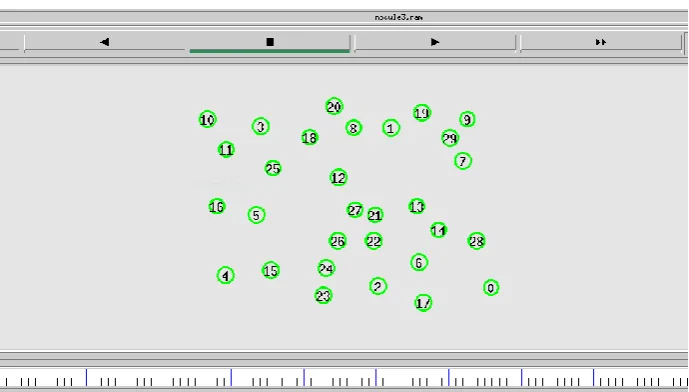
In fig.4.1 demonstrates the network animator file creation of 30 nodes places at random distances in simulation network area.
Fig 4.1 represents 30 nodes created from 0 to 29 places at random distance.
Fig4.2 black colour nodes represent actor nodes, blue colour node represents Static node and brown colour node represents Dynamic nodes.
Fig.4.3 shows end to end delay for 30 nodes communication as seen in the plotted xgraph is end to end delay is continuously decreasing with increase in pause time using CPRRA technique.
Fig.4.3 Packet transmission in End to End Delay Vs Pause Time
Fig.4.4 Packet transmission in Average Delay Vs Pause Time
The fig.4.4 shows that when the pause time increases, the average delay of data packets also increases. The routes are connection between sources and required destination frequently changed and established.
Packet Delivery Ratio is an important performance metric to show how successful a protocol performs delivering packets from source to destination. Fig.4.5. represent 30 connection nodes generated plotted graph 92% of packet delivery data transmission with increasing of pause time intervals
.
Fig.4.6 Packet transmission in Throughput Vs Pause Time
The throughput result from Check Point Route Recovery Algorithm (CPRRA) Technique has been presented in Fig.4.6. This result has number of packets dropped or left wait for a route reduce the throughput. In this proposed work done the Dynamic sensor node is used to reduce the delay so that the energy level of the nodes is maintained.
V. CONCLUSION
The In this paper, prevention of node failure is done using AODV routing protocol, Check Point Route Recovery algorithm and Network Topology Management .These three methods are combined together to find the best route for packet transmission without much energy loss and to detect the node whose energy level is about to drain using a Static node which intimate the Dynamic node about the energy drop in a particular node. The Dynamic node searches for the nearest node whose energy level is high and also has less number of links. The failure node is replaced with the node whose energy level is high. This is done with the help of CPRRA. NTM maintains the path between the nodes without breaking for better communication between the nodes and the link is established even after the replacement of the node without affecting the packet transmission. Thus this results in a Reliable, Robust and energy-efficient communication between the nodes.In future, there is a possibility of producing better results while combining check Point Recovery Algorithm with other existing routing protocol such as AOMDV, and also other algorithm such as Ant colony algorithm . There is a scope for improving in finding the best path and energy efficiency of the node.
3. Hua Qu, Peng Zhang, Ji-Hong Zhao, “A New Local Repair Scheme Based on Link Breaks for Mobile Ad Hoc Networks”, Seventh Annual Communications Networks and Services Research Conference, 2009.
4. Li Ya ,Wang Pengjun , Luo Rong, Yang Huazhong , Liu Wei “Reliable Energy-Aware Routing Protocol for Heterogeneous WSN Based on Beaconing “, Page(s): 109 – 112, Publication Year: 2014 .
5. K. Sha, J. Gehlot, and R. Greve, “Multipath routing techniques in wireless sensor networks: A survey”, Wireless Personal Communications., volume. 7, no. 2, pp. 807–829, publication year: 2013.
6. Peng-Jun Wan and Chih-Wei Yi, “Coverage by Randomly Deployed Wireless Sensor Networks”, IEEE Transactions on Information Theory, Vol.52, no.6, pp.2658- 2669, June 2006.
7. Arjan Durresi, Vamsi Paruchuri and Leonard Barolli “Delay-Energy Aware Routing Protocol for Sensor and Actor Networks” , vol 1, Page(s): 292 – 298, Publication Year: 2005.
8. Reuven Cohen and Boris Kapchits “Energy-Delay Optimization in an Asynchronous Sensor Network with Multiple Gateways”, volume 3, Page(s): 98 – 106, Publication Year: 2011.
9. NS-2, The ns Manual (formally known as NS Documentation) available at http: //www. isi.edu/nsnam/ ns/doc.
10. K. Liu, J. Deng, P. K. Varshney, and K. Balakrishnan, “An acknowledgment- based approach for the detection of routing misbehavior in MANETs,” IEEE Trans. Mobile Comput., vol. 6, no. 5, pp. 536–550, May 2007.
BIOGRAPHY
Mr.K.Hanumanthu Naik is Research scholar in the Department of Computer Science & Technology, Sri Krishnadevaraya University, Ananthapuramu. He received Master of Computer Application (MCA) degree in 2010 from G.Pulla Reddy Engineering. College Kurnool is affiliated from Sri Krishnadevaraya University, Anantapur. He is also published two (IJCSIT, IJESRT) International Journal Papers. His research interests are Computer Networks (wireless Networks).