18th International Conference on Structural Mechanics in Reactor Technology (SMiRT 18) Beijing, China, August 7-12, 2005 SMiRT18-S02-1
STUDY ON LAYOUT AND CONSTRUCTION CONCEPT OF DMS
(MODULAR SIMPLIFIED MEDIUM SMALL REACTOR)
Shizuka Hirako
Hitachi Ltd.
1-1, Saiwai-cho 3-chome, Hitachi-shi
Ibaraki-ken, 317-8511, Japan
Phone: +81-294-55-4486
Fax: +81-294-55-9900
e-mail:[email protected]
Takahiko Hida
The Japan Atomic Power Company
1-1,Kanda-Mitoshiro-choChiyoda-ku
Tokyo, 101-0053, Japan
Phone: +81-3-4415-6661
Fax: +81-3-4415-6690
e-mail: [email protected]
Yuusuke Shimizu
(1)e-mail: [email protected]
Shigeru Yokouchi
(1)e-mail:
[email protected]
Yoshinori Iimura
(1)e-mail:
[email protected]
Yuuji Yasuda
(1)e-mail: [email protected]
Kumiaki Moriya
(1)e-mail: [email protected]
(1)
Hitachi Ltd
ABSTRACT
Nuclear power is expected to become the main source of electric power generation in Japan for reasons of
energy security and prevention of CO2 emissions. In addition, the recent slowdown of electric power demand and
the liberalization of the electric power market are accelerating medium and small sized reactor development. Under these circumstances, DMS’s (modular simplified & medium small reactors) have been developed as 400MWe class LWR’s supported by the Japan Atomic Power Company. In the development of medium and small sized reactors, the most important point is how to overcome the scale demerits. To this end, we have pursued not only the simplification of systems and equipment but also the standardization of layout and construction.
The main technical feature of DMS’s is the adoption of a natural circulation reactor with short length fuel. Short length fuel enables the reduction of RPV height as well as construction volume of the PCV and building volume. A natural circulation reactor has considerable rationalizing effects such as the elimination of re-circulation pumps and their drive power source.
By applying simplified systems and equipment, a rationalized layout and construction method are adopted. To improve the constructability by means of
modular construction methods, steel containment is applied. The PCV size is reduced to 17m in diameter and 24m in height by applying a dish-shaped drywell and eccentric RPV arrangement. By applying a compact PCV and concentrated equipment arrangement in building, it can be confirmed that the ratio of building volume per unit power is equivalent to that of existing large sized ABWRs. Furthermore, a steel plate reinforced concrete structure (SC structure) is applied to the building layout.
realized by using three specific technologies, namely 3D-CAD, large crawler cranes and module fabrication factories, which have been established through actual plant construction. Thus, work in the field can be reduced to a large extent and, as has been confirmed, a construction period of two years is possible.
Keywords: Layout, Construction, Module, Medium and small sized Reactor, Simplified Reactor
1. INTRODUCTION
Many studies have been performed on medium and small sized reactors for commercial power, and many plant concepts have been proposed.
However, medium and small reactors were not constructed because of their economic inferiority to large LWR’s and of large development factors. Therefore, it is a top priority for DMS’s having economic improvements with proven technologies to be constructed at an early stage.
In the development of medium and small sized reactors, the most important point is how to overcome the scale demerit. To this end, we have pursued not only the simplification of systems and equipment but also the standardization of layout and construction. The main technical feature of DMS’s is the adoption of a natural circulation reactor with short length fuel. A natural circulation reactor has large rationalizing effects such as the elimination of re-circulation pumps and their drive power source. Short length fuel enables RPV height reduction as well as construction volume reduction of the PCV (Primary Containment Vessel) and reactor building volume. In addition to these, FSS (Free Surface Separation) can be applied to a natural circulation reactor because the steam evaporation speed inside the RPV is low. The adoption of FSS produces many advantages, such as a natural circulation force increment due to the decrease of core pressure drop, core internal simplification, RPV height reduction and a shorter annual maintenance period.
Besides system rationalization, layout standardization has been adopted as cost reduction measures. Rationalized layouts can be achieved by adopting an eccentricity PCV and full standard layout concept.
In this paper, the plant layout and construction method for the DMS’s are mainly described.
2. DESIGN TARGETS AND PLANT CONCEPT
When developing medium and small sized reactors, the following development targets are set. -Plant output to be 400 MWe class.
-Construction cost shall compete with current ABWR’s. -Large scale confirmation test should not be required. -Safety level should be equal to current ABWR’s.
-Short construction period of two years should be achieved.
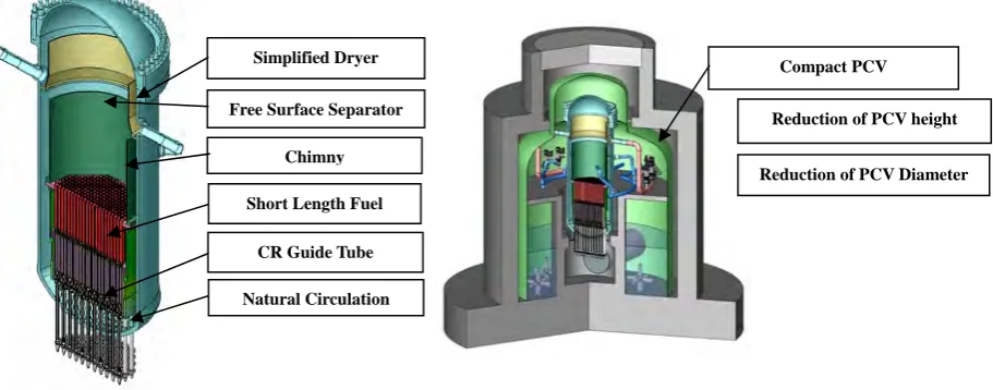
DMS’s plant concept is shown in Fig. 1 in which we pay particular attention to overcome the scale demerit
and to meet the above development targets. The main technical features of DMS’s are system simplification and compact layout arrangement by adopting a natural circulation reactor.
The main features of DMS’s are as follows:
Simplified Dryer
Free Surface Separator
Chimny
Short Length Fuel
CR Guide Tube
Natural Circulation
Compact PCV
Reduction of PCV height
Reduction of PCV Diameter
(1) Simplified reactor core structures
Application of small sized natural circulation reactor, the elimination of steam separator, the application of small sized reactor pressure vessel, etc.
(2) Simplified systems and safety systems
Two main steam lines, passive system, common use of systems, simplified ECCS structure, etc. (3) Rationalized layout
Compact PCV and building layout on which simplified systems and facilities are applied.
3. SYSTEM DESIGN OF DMS
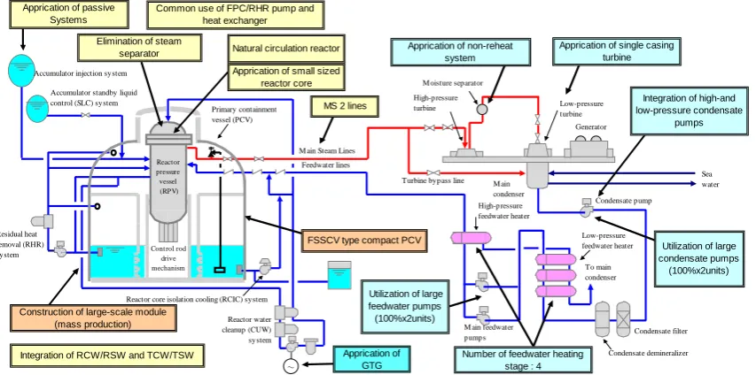
The system configuration of NSSS and BOP is shown in Fig. 2.
DMS’s systems are rationalized by a reduction in the system train number with large capacity equipment, systems having integrated functions, passive systems, and non-specific devices. For example, DMS’s adopt two main steam pipes, a single casing turbine and a single train of CW system by the adoption of large capacity components. As for integrated systems, RCW and TCW are integrated to a single system, as are FPC and SPCU. Gas turbine type emergency generators are also adopted from non-specific devices. As for passive systems, an accumulator is adopted for ECCS networks with a view to cost reduction.
Looking at the BOP specifications for the 400MWe class, a TCDF 52, reheat cycle, and six feed water heaters are adopted. In addition, a low pressure condensate pump and high pressure condensate pump are integrated to a single common pump, and feed water heaters are designed as a single train. Other system specifications are shown in Table 1.
Figure 2 Main configuration and features of DMS-400 Accumulator standby liquid
control (SLC) system
Residual heat removal (RHR) system Reactor water cleanup (CUW) system
M ain Steam Lines
Feedwater lines Primary containment vessel (PCV) Reactor pressure vessel (RPV)
Reactor core isolation cooling (RCIC) system Cont rol rod
drive
mechanism Accumulator injection system
To main condenser Condensate filter Condensate demineralizer Condensate pump Generator M ain condenser High-pressure turbine Low-pressure turbine
M ain feedwater pumps
Sea water M oisture separator
Turbine bypass line
High-pressure feedwater heater
Low-pressure feedwater heater
Number of feedwater heating stage : 4
Integration of high-and low-pressure condensate
pumps Natural circulation reactor
MS 2 lines
FSSCV type compact PCV
~
Apprication of small sized reactor core
Integration of RCW/RSW and TCW/TSW
Common use of FPC/RHR pump and heat exchanger
Construction of large-scale module (mass production) Apprication of passive
Systems
Apprication of GTG
Utilization of large feedwater pumps (100%x2units)
Utilization of large condensate pumps (100%x2units) Apprication of non-reheat
system
Apprication of single casing turbine Elimination of steam
separator
4. LAYOUT AND CONSTRUCTION
Based on the above explained rationalization of systems and facilities, the concept of building layout and plant construction method was established aiming at reducing the quantity of construction material, shortening the construction period, and standardizing the plant design. As a result, it was confirmed that the ratio of building volume per unit output power can be made equivalent to that of existing large sized ABWRs. In addition, for plant construction, it becomes possible to reduce the work in the field and shorten the construction period to a large extent by applying the large-scale modular construction of factory production type, in which equipment, facilities and building structures are integrated.
4.1 CONCEPT OF BUILDING LAYOUT
Based on the design targets of DMS’s explained in chapter 2 and the main system configuration of DMS’s explained in chapter 3, the following 3 items were included in the concept of building layout in order to overcome the disadvantage in economy due to scale demerit, compared with existing ABWRs.
- Improvement of economy - Improvement of constructability - Standardization of design
4.1.1 IMPROVEMENT OF ECONOMY
As the measures to improve economy by building layout, investigation was made to reduce the building volume that has a great influence on the quantity of construction material, based on above explained rationalization of systems and equipments. The measures for achieving compactness in primary containment vessel (PCV), which is accommodated in reactor building, and building layout are described as follows:
1) Primary containment vessel (PCV)
Concerning PCV, the pressure suppression containment that is experienced in BWRs and ABWRs was applied while compactness was aimed at by eliminating steam separator, thus reducing the height of reactor pressure vessel (RPV) and the number of main steam pipes.
In addition, to improve the constructability by means of modular construction method, steel
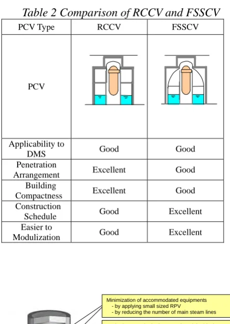
containment was applied. Table 2 shows a comparison between RCCV (Rein-forced concrete
containment) and FSSCV (Free standing steel containment Vessel). Though both type PCV are well applicable to DMS’s, FSSCV type PCV was selected especially from the point of shorter construction schedule and easier applicability to modularization.
Design pressure (427 kPa) was set to equivalent to that of improved type of Mark-I, and the quantity of material was reduced by reducing the diameter and height of PCV by adopting dish shape drywell and eccentric RPV arrangement. Thus, the concept of compact PCV that improves constructability was
established as shown in Fig. 3.
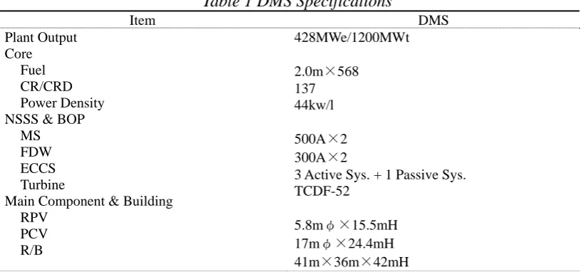
Table 1 DMS Specifications
Item DMS Plant Output
Core Fuel CR/CRD Power Density NSSS & BOP
MS FDW ECCS Turbine
Main Component & Building RPV
PCV R/B
428MWe/1200MWt
2.0m×568
137 44kw/l
500A×2
300A×2
3 Active Sys. + 1 Passive Sys. TCDF-52
5.8mφ×15.5mH
17mφ×24.4mH
2) Building layout
In addition to the rationalization of systems and equipments (the application of passive system, the reduction of the number of systems, etc.) as explained in chapter 3, the classification of radiation dose rate was reexamined, and the quantity of long materials (piping, cable, ventilation and air conditioning duct, etc.) was reduced by high concentration of the equipment and facilities, which made it possible to efficiently use space and realize compact building.
Further, the concept of building layout that contributes to reducing the construction cost was established by applying steel plate reinforced concrete structure (SC structure), simplifying the shape of building, and simplifying the building structure.
4.1.2 IMPROVEMENT OF CONSTRUCTABILITY
Building layout was determined, taking the improvement of constructability and the shortening construction period into consideration, and building was simplified by applying SC structure, as explained above.
Thus, the layout that facilitates modularization was realized. In addition, to enhance the constructability, the number of building stories was reduced, the facilities that become critical in installation work were arranged in low stories as much as possible, and non-controlled areas were concentrated.
Fig. 3 Concept of compact primary containment vessel
Reduction of PCV height
- by making the upper D/W of PCV into dish shape PCV
Reduction of PCV height
- by reexamining PCV internal pressure (427 kPa) Method to carry in the integrated modular block of containment and biological shielding wall
- by applying steel containment
- by applying SC stracture to biological shielding wall
Reduction of PCV diameter
- by eccentric RPV and PCV arrangement Minimization of accommodated equipments
- by applying small sized RPV
- by reducing the number of main steam lines
Table 2 Comparison of RCCV and FSSCV
PCV Type RCCV FSSCV
PCV
Applicability to
DMS Good Good
Penetration
Arrangement Excellent Good
Building
Compactness Excellent Good
Construction
Schedule Good Excellent
Easier to
These arrangements, the application of the above explained compact PCV (steel containment) and the SC structure building make it easier to apply large-scale modular construction method equipment, facilities and building structures are integrated.
Fig. 4 shows the building configuration, which improves constructability.
Thus, the layout concept was established that contributes to improving constructability by reducing the work for field installation as well as shortening period.
4.1.3 STANDARDIZATION OF PLANT DESIGN
In order to reduce construction cost, the standardization of plant design is important especially for small sized reactors. Therefore, aiming at the standardization of plant design, the structure of the entire building and the layout in it were determined, by eliminating those obstructing standardization of the factors due to external conditions which is inherent to each site.
And the area was divided into fixed arranging area and variable arranging area. By zoning the layout in this way, the arrangement that makes standardized areas hardly influenced by variable factors can be realized. Concretely, secondary containment area in reactor building is made to be the area for arranging fixed parts, in which standardization is carried out as much as possible. On the other hand, the circumferential area, which includes electrical equipment, plant make up facilities, etc., is made to be the area for arranging variable parts. Thus, the layout concept that makes variable factors have no influence on standardized areas was established.
Fig. 5 shows the standardized of plant design.
It was confirmed that these concepts of rationalized layout make it possible to realize the rate of building volume per unit output power that is equivalent to existing large sized ABWRs plant aims at the reduction of fieldwork and construction period by widely applying of modularization.
4.2 CONCEPT OF CONSTRUCTION METHOD
Recently, construction method of nuclear power plant aims at the reduction of fieldwork and construction period by widely applying of modularization.
The construction method using large cranes has been applied to construct existing ABWRs, having the
experience of modules the maximum weight of which is approximately 700 ton. For small sized reactors, in addition to the experience and technology of conventional modular construction, the concept of construction method was established that makes it possible to assemble equipment, piping, etc. in factory, and to minimize the temporary structures, and to reduce the quantity of field installation material and construction period.
This achievement depends on a large extent by applying steel plate reinforced concrete (SC) structure as well as the BM (building/machine) integrating modular construction of factory production type in which SC plate
RHR RHR
CRD CUW
RCIC Electrical
Panel Room
PCV
Standardized Area (Controlled Area)
Fig. 5 Standardization of Plant Design
Variable Area(Non-controlled Area) SC structure
excluding internal concrete, equipment and piping are integrated.
Fig.6 shows the concept of construction method. As shown in Fig.6, BM integrating modular construction
method is in harmony with plant layout, machinery, and building.
4.2.1 BM INTEGRATING MODULAR CONSTRUCTION
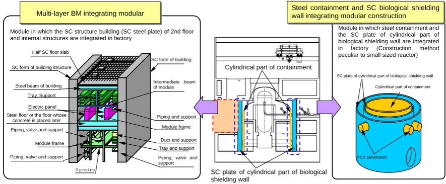
Fig. 7 shows the concept of the modular construction for carrying in a module in which equipment, facility and
building structures are integrated.
.
1) Steel containment and SC structure biological shielding wall integrating modular construction
In order to early start the work of primary containment vessel that becomes critical in construction schedule as well as the works of peripheral building structures and facilities, the internals of primary containment vessel were made into large blocks as much as possible and assembled into modules in which equipment, facilities and building structure are integrated in factory.
The applying of compact steel containment and the application of SC structure to the biological shielding wall that is constructed around the primary containment vessel make it possible to apply BM integrating modular construction that integrates steel containment (including penetration) and the SC steel plate of biological shielding wall into one. This method not only rationalizes the work of primary containment vessel but also reduces construction period.
Fig. 7 Concept of the modular construction
Module in which steel containment and the SC plate of cylindrical part of biological shielding wall are integrated in factory (Construction method peculiar to small sized reactor)
SC plate of cylindrical part of biological shielding wall
Cylindrical part of containment
SC plate of cylindrical part of biological shielding wall
PCV penetration
Cylindrical part of containment Steel containment and SC biological shielding wall integrating modular construction
Module in which the SC structure building (SC steel plate) of 2nd floor and internal structures are integrated in factory
Multi-layer BM integrating modular
SC form of building structure Half SC floor slab
Piping, valve and support Steel beam of building
Tray, Support Electric panel Steel floor or the floor whose
concrete is placed later
Module frame Piping, valve and support
Intermediate beam of module
Piping, valve and support SC form of building
Module frame
Tray and support Duct and support
O peration
Piping and support
B
BM
M
iinntteeggrraattiinnggmmoodduullaarrccoonnssttrruuccttiioonn /Constructionshortning /Modular Construction
/Compact /Standardization
/Pre-fabricati on /SC & Steel structure
B
Bu
ui
il
ld
di
in
ng
g
Plant Layout
M
M
a
a
c
c
h
h
i
i
n
n
e
e
r
r
y
y
2) Multi-layer BM integrating modular construction
The central control room and electrical equipment room of reactor building are important areas for the processes of power receiving and test, so that the work of electrical equipment room needs to be started early to secure the time required for field installation. For DMS’s, including the 2nd story of building in the scope of BM integrating modular construction, multi-layer BM integrating modular construction was applied, in which the SC steel plate of building, intermediate reference floor and electrical panels and other products that are to be
arranged on floor are integrated. By applying multi-layer BM integrating modular construction, it becomes possible to assemble in factory the
cabling between panels and free access floor and other structures, which can conventionally be installed only in the field. Thus, the work in the field can be reduced to a large extent. In addition, by applying room modules that are divided by the rooms, highly complete modules with masking for transportation and installation can be realized. Making these modules into large blocks according to the capacity of available cranes, it is possible to reduce the number of modular blocks and thus cut tie-in works.
4.2.2 CONSTRUCTION PERIOD
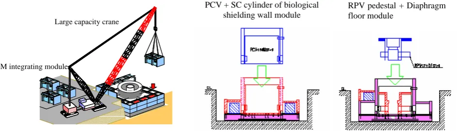
In addition to the rationalization of systems and facilities and the reduction of the quantity of construction materials, by applying the above explained factory production type BM integrating modular construction and carrying in and installing the integrated modular blocks with large capacity cranes, it becomes possible to early start the work of critical areas.
Fig. 8 shows the example of the installing the integrated modular blocks by using large capacity cranes.
Taking the reduced time of startup test also into account, the construction period of approximately two years
(from rock-bed inspection to operation start) became possible as shown in Fig.9.
Besides, quality and reliability can be improved further by applying the highly complete modules manufactured in factory, and indirect costs can be cut by reducing the work for field installation.
It was confirmed that the disadvantages of small sized reactors from the viewpoint of facility configuration and the quantity of construction materials, compared with large sized reactors, will be overcome in the future by further rationalizing the building layout and investigating the measures to improve constructability.
BM integrating module
Large capacity crane
PCV + SC cylinder of biological shielding wall module
RPV pedestal + Diaphragm floor module
Fig. 8 Example of the installing the integrated modular blocks
Building
PCV
Machinery
Major Module
26 Milestone
22 23 16 17 18 19 20 21 24 25 12 13 14 15
8 9 10 11
4 5 6 7
-1 1 2 3
R/I PCV Start O/F Completed Crane F/L C/O
▽ ▽ ▽ ▽ ▽ ▽
L/T
R/I: Rock Inspection O/F: Operating Floor L/T: Leak Test F/L: Fuel Loading C/O: Commercial Operation
5. CONCLUSION
The basic design policy of DMS’s is to optimize the design according to the output power level of plant and achieve high economy by fully utilizing proved technologies of existing reactors. Since there is a good prospect presently concerning the economy of DMS’s due to the simplification of systems, building, etc., the possibility of introducing it to the market in near future, aiming at constructing in 2010’s, becomes high. We want to further improve economy and strengthen international competitive power and promote the construction of DMS’s in the future in the countries and regions where the demand for medium to small sized reactors is high.
REFERENCES
[1] T.Hida,, G.Ito, “Status of Innovative Small-Sized LWR Development in JAPAN”, Proceedings of the 2nd
Asian Specialist Meeting on Future Small-Sized LWR Development”, November 2003
[2] M.Matsuura, “Development of medium sized ABWR (ABWR-600, ABWR-900)”, Proceedings of the
Eleventh International Conference on Nuclear Engineering (ICONE11), April 2003
[3] A. Kawahara, “Advanced Design and Construction Technology for ABWR”, Proceedings of International