R
OBUST
V
IRTUAL
E
NERGY
K
EY MANAGEMENT
BASED
L
OCATION
V
ERIFICATION SYSTEM FOR
WSN
K.Rajesh,
1S.Manikandan
2PG Scholar, Department of ECE, PSN College of Engineering and Technology, Tamilnadu, India1
Assistant Professor, Department of ECE, PSN College of Engineering and Technology, Tamilnadu, India2
Abstract: Localization in wireless sensor networks, i.e., knowing the location of sensor nodes, is very important for many applications such as environment monitoring, target tracking, and geographical routing. Since wireless sensor networks may be deployed in hostile environment, sensors’ localization is subjected to many malicious attacks. Therefore, sensors’ locations are not trstworthy and need to be verified before they can be used by location-based applications. Previous verification schemes either require group-based deployment knowledge of the sensor field, or depend on expensive or dedicated hardware, thus they cannot be used for low-cost sensor networks. In this project, we propose a lightweight location verification system. In addition, we propose vector based virtual energy key management based privacy information transfer for WSNs that significantly reduces the number of transmissions needed for rekeying to avoid stale keys. It is a secure communication frame-work where sensed data is encoded using a scheme based on a permutation code generated via the RC4 encryption mechanism. The key to the RC4 encryption mechanism dynamically changes as a function of the residual virtual energy of the sensor.Thus, a one-time dynamic key is employed for one packet only and different keys are used for the successive packets of the stream. The intermediate nodes along the path to the sink are able to verify the authenticity and integrity of the incoming packets using a predicted value of the key generated by the sender’s virtual energy, thus requiring no need for specific rekeying messages. It is able to efficiently detect and filter false data injected into the network by malicious outsiders. Our results show that, without incurring transmission overhead, is able to eliminate malicious attack from the network in an energy
I. INTRODUCTION
lightweight verification algorithm should be designed that can effectively perform on-spot verifications.
A. SYSTEM MODEL AND ASSUMPTIONS:
In our system, all sensor nodes can estimate their locations in the field using any of the existing localization schemes. These locations are called sensors’ estimated or claimed locations, and the distances between sensors’ estimated locations and
true locations are called localization errors. The
communication range of a sensor is a circle centered at the sensor’s true location and has a certain radius. We assume all sensors’ communication ranges have the same radius. Each sensor broadcasts its ID within its communication range, and passively overhears IDs broadcast by other sensors.
B.PROBLEM STATEMENT:
In this paper, we intend to design a verification system in which the VC can effectively determine if sensors’ estimated locations are trustable. According to the requirements of different applications, the system should provide either on- spot or in-region verification results. On-spot verification is to verify whether a sensor’s estimated location is away from its true location less than a certain distance; in-region verifica- tion, on the other hand, is to verify whether a sensor is within a geographical region given that its estimated location is in that region. If the verification succeeds, the location will be recognized by the VC as a correct location, otherwise, it will be recognized as a wrong one. The verification system should have following properties. First, the verification algorithm should be lightweight in terms of hardware cost and computation overhead
C.LIGHTWEIGHT ON-SPOT VERIFICATION:
In this section, we propose two algorithms for on-spot verification. The first one is named Greedy Filtering using Matrix. The second one is named Greedy Filtering using Trustability-indicator. Both algorithms utilize the inconsis- tency between sensors’ estimated locations and neighbor- hood observations. They can be used in different scenarios according to the application’s requirements, and we will compare the two algorithm.
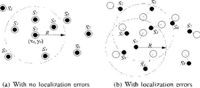
Fig. 1. Snapshot of sensor field
D.Greedy Filtering Using Matrix:
In this section, we discuss the GFM verification algorithm. The first step in the verification process is that each sensor broadcasts its ID within its communication range and meanwhile overhears the IDs broadcast by other sensors. We denote sensor Si’s neighborhood observation by Oi. As an example, Fig. 1a shows a scenario where sensors are localized accurately with zero errors. The solid circles and the hollow circles represent sensors’ true and estimated locations, respectively. Sensor S0’s true location is L ¼ðx0;y0Þ and its communication range is the big dashed circle. Because sensor S1;S2;S3;S4 are in the communication range of sensor S0, their ID messages can reach S0. Hence, sensor S0’s neighborhood observation is O0 ¼ðS1;S2;S3;S4Þ. Then, each sensor sends its neighborhood observation and its estimated location to the VC. The VC will analyze all the information collected from sensors and detect if there is any inconsistency. The intuition is that when sensors are correctly localized with small localization errors, then their neighborhood observations should be consistent with their estimated locations. For example, in Fig. 1a, all sensors are localized with ZERO errors. The distance between the estimated locations of S0 and S1 is less than the radius R, which is consistent with the fact that they can observe each other. Based on this intuition, GFM algorithm organizes all the information in the form of matrix to find information inconsistencies.
II. CONSTRUCTIONS OF MATRIXES:
Elements in this matrix are either 1 or 0 depending on whether sensors can observe each other, namely
where i; j 2f1; ... ;ng are the row and column index. Note that because of environmental disruptions, two sensors may not observe each other at the same time, so matrix Mo is not a symmetric matrix.
A.ESTIMATION MATRIX:
This matrix is computed using sensors’ estimated locations. If the distance between Si’s and Sj’s estimated locations is less than R, the radius of communication range, then the element at row i and column j will be 1, otherwise, it will be 0,
where dij denotes the distance between the estimated locations of sensors Si and Sj
B.METRIC FOR FILTERING ABNORMAL LOCATIONS
Active Difference Metric
Where i 2f1; 2; ... ;ng. For a sensor Si, metric ADi is the sum of elements in ith row of matrix Minc. This metric quantifies the inconsistency between sensor Si’s neighborhood observation and the estimated locations.
Passive Difference Metric
where i 2f1; 2; ... ;ng. For a sensor Si, metric PDi is the sum of elements in ith column of matrix Minc. This metric quantifies the inconsistency between other sensors’ observation on Si (namely, sensor Si is passively observed) and the estimated locations of sensors.
C.GREEDY FILTERING PROCEDURE:
In this section, we describe how GFM algorithm calculates all the above matrixes and utilizes filtering metrics to greedily filter out abnormal locations. The procedure is shown in Fig. 3. In the first round, VC computes matrix Minc and metrics ADi, PDi, and ASi for all i 2f1; 2; .. If there is any sensor whose
metric value exceed that metric’s threshold, VC revokes the sensor that has the largest metric value (say node Sk), and sets all zeros to the kth row and the kth column in matrixes Me, Mo, and Minc. This process repeats until no more sensors can be filtered out. Then the metric CNi is considered: sensors that do not have enough number of consistent neighbors are revoked. Finally, the remaining sensors are accepted by the VC as correctly localized sensors.In the above procedure, the threshold for different metric can be obtained through offline training using experimental data. In our simulations, we deploy sensors randomly in a square field and localize them with errors less than the anomaly degree. Then we compute all the matrixes and the values of ADi, PDi, ASi, and CNi for all sensors. The threshold value is determined according to the desired false alarm rate. For example, if the application requires that the false alarm rate should be smaller than 5 percent, then we set the thresholds for metric AD, PD, and AS at the 95 percent percentile and the threshold for metric CN at the 5 percent percentile. Given the value of communication range radius, the node density,the accuracy of the localization algorithms used in the field and the environmental parameters, we can construct experiments accordingly and obtain the above threshold values.
D.GREEDY FILTERING USING TRUSTABILITY-INDICATOR
In this section, we discuss the GFT verification algorithm. In GFT algorithm, VC computes a trustability indicator for each sensor and updates the indicator’s value in multiple rounds. In each round, if a sensor’s indicator is higher than the threshold, the sensor is accepted as correctly localized sensor. Such iteration stops when all sensors’ indicators become stable. Finally, the sensors that have indicator values lower than the threshold are detected and revoked.
III. LIGHTWEIGHT IN-REGION VERIFICATION:
A.VERIFICATION REGION DETERMINATION: Given a location-based application, we define the verification region as the physical region inside which the sensor should be verified if and only if the application goal can be achieved
where Li is the true location of sensor Si, and Vi is the verification region for sensor Si. Notice that the verification region for different sensors may be different. In addition, we define two variants to the above region, and name them sufficient region and necessary region, respectively,where ~ Vi is the sufficient region and ^ Vi is the necessary region. From the geographical point of view, region ~ Vi is fully contained by region ^ Vi. For different applications, the verification regions should be determined according to the specific application’s requirement. Please refer to the supplementary file, which is available online, where we use a location-based surveillance application to demonstrate how the verification region can be determined.
B.IN-REGION VERIFICATION:
In this section, we propose a lightweight algorithm that the VC can use to perform in-region verifications. This algorithm also utilizes sensors’ neighborhood observations. Basically, if two sensors observe each other, then the VC considers them to be a pair of “confirmed” neighbors. Then, VC derives a probability distribution for each sensor, which indicates how probably the sensor is at each point in the field. The distribution function can be either continuous or discrete. In the continuous version, the in-region confidence is computed by taking the integral of the distribution function within the verification region. In the discrete version, the in-region
confidence is the sum
Notice that communication range is the region that centers at a sensor’s true location with radius R. Here we define a variant named estimated communication range (ECR) which is a circle that centers at the sensor’s estimated location. The VC uses the ECRs of a sensor’s confirmed neighbors to divide the field into several regions. Each region has a score which is the number of the ECRs that cover this region. An example is shown in Fig. 6b, the solid and hollow circles represent
sensors’ true and estimated locations, respec-tively. Sensor S1
has three confirmed neighbors: sensors S2, S3, and S4. The
field is divided into six regions whichbelong to three districts.
The 0-scored district contains region A1; the 1-scored district
contains regions A2, A3, and A4; and the 2-scored district
contains regions A5and A6.
We notice that a sensor may not be inside the highest scored district, because the ECRs are estimated communica-tion ranges and may not cover a sensor’s true locacommunica-tion. However, we guess the probability that a sensor is inside a higher scored district is higher, given that sensors are localized with reasonable errors. In the following, we will prove this conjecture using simulation data.
directly used for our purpose. Otherwise, simulations should be conducted using proper network parameters. In our simulation, 600 sensors are randomly deployed in a square field of 300 m_300 m. The communication range is R ¼ 20 m. Each sensor averagely has 12 neighbors in itscommunication range. The environmental disturbance is quantified by f¼10%, which means a sensor has 90 percent chance to receive a beacon message from its neighbor. For each sensor, we record the number of confirmed neighbors it has, then we divide the field into several scored districts and record which scored-district contain the sensor’s true location.
IV. VIRTUAL ENERGY KEY MANAGEMENT: It is essentially the method used for handling the keying process. It produces a dynamic key that is then fed into the crypto module. In VEBEK, each sensor node has a certain virtual energy value when it is first deployed in the network. After deployment, sensor nodes traverse several functional states. The states mainly include node-stay-alive, packet reception, transmission, encoding and decoding. As each of these actions occur, the virtual energy in a sensor node is depleted. The current value of the virtual energy, Evc, in the node is used as the key to the key generation function, F. During the initial deployment, each sensor node will have the same energy level Eini, therefore the initial key, K1, is a function of the initial virtual energy value and an initialization vector (IV). The IVs are pre-distributed to the sensors. Subsequent keys, Kj, are a function of the current virtual energy, Evc, and the previous key Kj−1. VEBEK’s virtual energy-based keying module ensures that each detected packet is associated with a new unique key generated based on the transient value of the virtual energy. After the dynamic key is generated, it is passed to the crypto module, where the desired security services are implemented. The process of key generation is initiated when data is sensed; thus, no explicit mechanism is needed to refresh or update keys.
Moreover, the dynamic nature of the keys makes it difficult for attackers to intercept enough packets to break the encoding algorithm. transient value of its virtual energy after performing some actions. Each action (or state traversal) on a node is associated with a certain predetermined cost. Since a sensor node will be either forwarding some other sensor’s data or injecting its own data into the network, the set of actions and their associated energies for VEBEK includes packet reception (Erx), packet transmission (Etx), packet
encoding (Eenc), packet decoding (Edec) energies, and the
energy required to keep a node alive in the idle state (Ea).
Specifically, the transient value of the virtual energy, Ev, is
computed by decrementing the total of these predefined associated costs, Evc, from the previous virtual energy value.
As mentioned above, each node computes and updates the
The exact procedure to compute virtual cost, Evc, slightly
differs if a sensor node is sensor). In order to successfully decode and authenticate a packet, a receiving node must keep track of the energy of the sending node to derive the key needed for decoding.
V. SECURITY ANALYSIS
When WSNs are deployed in hostile environment, just like the adversaries can attack the localization schemes to make sensors’ locations wrongly estimated, they can also attack the verification algorithms to make abnormal locations not detected by the VC. In GFM algorithm, the attackers can compromise a sensor and force it to report fake neighborhood observation that is consistent with the claimed location. In GFT algorithm, since consistent neighbors can increase a sensor’s indicator, attackers may sophisticatedly generate consistent neighbors around a victim sensor. In the in-region verification algorithm, since the VC relies on sensors’ neighborhood observations to derive probability distributions, the attackers can distort neighborhood observations. It is important that our algorithm is robust in presence of malicious attacks.
VI. CONCLUSION
claimed by sensors are far from their true spots beyond a certain distance. The in-region verification verifies whether a sensor is inside a verification region. To provide the confidence, a probabilistic method is designed. Our work takes the first step to integrate the application requirements in determining the trustability of sensors’ estimated locations. In addition, our proposed verification system is more effective and robust compared to previous works. It yields satisfactory verification results to a variety of applications; furthermore, it is resilient to malicious attacks and can be used in hostile environments.
ACKNOWLEDGEMENT
The authors acknowledge the contributions of the students, faculty of PSN College of Engineering and Technology for helping in the design of test circuitry, and for tool support. The authors also thank the anonymous reviewers for their thoughtful comments that helped to improve this paper. The authors would like to thank the anonymous reviewers for their constructive critique from which this paper greatly benefited.
REFERENCES
[1] D. Liu, N. Peng, and W.K. Du, “Attack-Resistant Location Estimation in Sensor Networks,” Proc. Fourth Int’l Symp. Informa- tion Processing in Sensor Networks (IPSN ’05), 2005.
[2] D. Moore, J. Leonard, D. Rus, and S. Teller, “Robust Distributed Network Localization with Noisy Range Measurements,” Proc. Second ACM Conf. Embedded Networked Sensor Systems (SenSys ’04), 2004.
[3] R. Nagpal, H. Shrobe, and J. Bachrach, “Organizing a Global Coordinate System from Local Information on an Ad Hoc Sensor Network,” Proc. Second Int’l Conf. Information Processing in Sensor Networks (IPSN ’03), 2003.
[4] D. Nicolescu and B. Nath, “Ad-Hoc Positioning Systems (APS),” Proc. IEEE GLOBECOM, 2001.
[5] D. Niculescu and B. Nath, “Dv Based Positioning in Ad Hoc Networks,” J. Telecomm. Systems, vol. 22, pp. 267-280, 2003.
[6] D. Niculescu and B. Nath, “Ad Hoc Positioning System (APS) Using AoA,” Proc. IEEE INFOCOM, 2003. [23] N. Sastry, U. Shankar, and D. Wagner, “Secure Verification of Location Claims,” Proc. ACM Workshop Wireless Security (WiSe), 2003.
[7] R. Want, A. Hopper, V. Falcao, and J. Gibbons, “The Active Badge Location System,” ACM Trans. Information Systems, vol. 10, no. 1, pp. 91-102, 1992.
[8] B. Waters and E. Felten, “Secure, Private Proofs of Location,” Technical Report TR-667-03, Princeton Computer Science, 2003.
[9] Y. Wei, Z. Yu, and Y. Guan, “Location Verification Algorithms for Wireless Sensor Networks,” Proc. Int’l Conf. Distributed Computing Systems (ICDCS), 2007
[10] A. Youssef and M. Youssef, “A Taxonomy of Localization Schemes for Wireless Sensor Networks,” Proc. Int’l Conf. Wireless Networks (ICWN ’07), pp. 444-450, 2007.
[11] Y. Zeng, J. Cao, J. Hong, S. Zhang, and L. Xie, “Secure Localization and Location Verification in Wireless Sensor networks: A Survey,” J. Supercomputing, pp. 1-17, 2010.
[11] L. Lazos and R. Poovendran, “Hirloc: High-Resolution Robust Localization for Wireless Sensor Networks,” Proc. IEEE J. Selected Areas in Comm., vol. 24, no. 2, pp. 233-246, Feb. 2006.
[12] D. Liu, P. Ning, A. Liu, C. Wang, and W. Du, “Attack-Resistant Location Estimation in Wireless Sensor Networks,” ACM Trans. Information System Security, vol. 11, no. 4, pp. 1-39, 2008.
[13] M. Talasila, R. Curtmola, and C. Borcea, “LINK: Location- Verification through Immediate Neighbors Knowledge,” technical report, Dept. of Computer Science, NJIT, 2010
[14] K. Rasmussen and S. Capkun, “Location Privacy of Distance Bounding Protocols,” Proc. 15th ACM Conf. Computer and Comm. Security (CCS ’08), pp. 149-160, Oct. 2008
[15] N. Tippenhauer and S. Capkun, “Id-Based Secure Distance Bounding and Localization,” Proc. 14th European Conf. Research in Computer Security (ESORICS ’09), pp. 621-636, 2009.
[16] J.T. Chiang, J. Haas, and Y.-C. Hu, “Secure and Precise Location Verification Using Distance Bounding and Simultaneous Multi- lateration,” Proc. Second ACM Conf. Wireless Network Security (WiSec ’09), pp. 181-192, 2009.
[17] N. Chandran, V. Goyal, R. Moriarty, and R. Ostrovsky, “Position Based Cryptography,” Proc. Int’l Cryptology Conf. (CRYPTO ’09), pp. 391-407, 2009.
[18] V. Shmatikov and M.-H. Wang, “Secure Verification of Location Claims with Simultaneous Distance Modification,” Proc. 12th Ann. Asian Computing Science Conf. (Asian ’07), pp. 181-195, Dec. 2007
BIOGRAPHY
K.Rajesh has received B.E degree in Electronics and Communication Engineering from Anna University, chennai 2012. He is currently pursuing Master of Engineering in Communication Systems in PSN College of Engineering and Technology under Anna University, Chennai. Her areas of interest in research are Wireless communication and Digital Electronics.