Transactions of the 17th International Conference on Structural Mechanics in Reactor Technology (SMiRT 17) Prague, Czech Republic, August 17 –22, 2003
Paper # F03-7
Structural Mechanics Analysis of Intermediate Heat Exchanger for Prototype
Fast Breeder Reactor
R. Srinivasan, Alok Gupta, P. Chellapandi, S.C. Chetal and S.B. Bhoje
Indira Gandhi Center for Atomic Research, Kalpakkam, India
ABSTRACT
For the straight tube design of Intermediate Heat Exchanger of 500 MWe Prototype Fast Breeder Reactor, Structural mechanics analyses have been completed for meeting the design target of 40 y in compliance with design code RCC-MR. Based on parametric studies, tubesheet thickness of 150 mm, 3600 tubes of 19.0 mm OD and 0.8 mm wall thickness arranged in 25 rows with intermediate supports having a maximum span of 675 mm have been selected. In this paper, some of the structural mechanics analysis carried out for the selected design and their results are presented. The contribution of straight tubes in sharing the mechanical loads (loads due to differential pressure on tubesheets and load due to pressure on bottom dished end) has been realistically estimated based on buckling and pullout strength aspects. Experiments have been carried out to confirm the buckling and pullout strengths of the tubes. The effect of steady state / transient thermal loadings on the buckling / pullout strengths have been considered. Tubes are also checked for FIV based on analyses as per ASME Appendix.N and model studies. The structural integrity of IHX under seismic loading has been confirmed by analysis and under CDA loading by experiments.
KEY WORDS: Anisotropic equivalent plate model, FE analysis, Effect of tubes, Experimental Investigation on buckling and pullout strengths, Thermal transients, FIV, Seismic analysis, CDA Experiments.
INTRODUCTION
In Prototype Fast Breeder Reactor (PFBR), there are four Intermediate Heat Exchanger (IHX) each of capacity 315 MWt, whichare used to transfer the
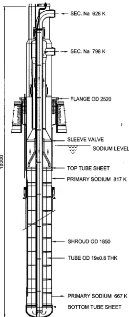
heat from radioactive primary sodium to non radioactive secondary sodium. IHX (Fig. 1) is a shell and tube heat exchanger with primary sodium on shell side and secondary sodium on tube side. The primary sodium radially enters the shell side at 817 K at top, flows vertically down, and finally leaves at 667 K to the cold pool. The secondary sodium enters through a central down comer pipe, takes 1800 turn, enters the tube sides at 628 K and leaves at 798 K. There are 3600
tubes (OD19 x 0.8 WT) arranged in 25 concentric rows around the down comer pipe. The tubes are rolled and welded to tubesheets at either end. The material of construction is SS316 LN and the design life is 40 Y. IHX is designed as per RCC-MR [1].
Considering the manufacturing simplicity, requirement of lower tubesheet thickness, uniform stress over the tube length and Flow Induced Vibration (FIV) rigidity, straight tube design is used. Since the tubes contribute significantly in sharing the loads on tubesheets, the tubesheet thickness is arrived at after considering the buckling of tubes and pullout strength of tube to tubesheet joints for thermo mechanical loadings including transients. In the analysis, the design thickness of tube is taken as 0.61 mm after considering under tolerance of 0.08 mm and corrosion/ degradation of 0.11mm so as to ensure the integrity at the end of 40 Y life. The basic thicknesses for various parts are arrived at so as to meet the design limits of RCC-MR. Based on the parametric study, the tubesheet thickness of 150 mm and tube bundle support spacing of 675 mm are chosen. Towards reducing thermal loading, the temperature difference among the tubes is minimized by providing a flow distribution plate at secondary sodium inlet.
This paper discusses some of the important structural mechanics investigations carried out on IHX viz. buckling of inner shell in the bundle region and tubes which are subjected to axial compression, pullout strength of tube to tubesheet joint, FIV analysis of tubes, analysis for seismic and CDA
strengths of the tubes. The effect of steady state / transient thermal loadings on the buckling / pullout strengths, FIV analyses carried out as per ASME Appendix.N and model studies for FIV are discussed. The structural integrity of IHX under seismic loading by FEM and under CDA loading by experiments are presented.
LOADINGS
Various parts of IHX are subjected to steady state pressure loading during normal operation and transient pressure loading during Large Sodium Water Reaction (LSWR) in Steam Generator (SG). IHX is subjected to a pressure of 0.8 MPa (at bottom dished end location) during normal operation and a peak pressure of 1.76 MPa due to a design basis leak in SG [2]. Based on thermal hydraulic analysis, the temperature distribution in the tube bundle is obtained. During steady state the average temperature of inner shell is colder than the net average temperature by ~ 6 K; the tubes in innermost row and the tubes in outermost row are colder than the net average by 14 K and 21K respectively. The hottest tubes (18th row) are hotter than the net average by 12 K. Apart, typical transients caused by events like loss of feed
water flow are considered for the buckling / pullout strength of tubes. The ∆T loadings for the loss of feed water event (governing transient) are
• ∆T of 22 K for the inner shell / tubes in inner row (hotter than net average) from the consideration of buckling
• ∆T of -26 K for the tubes in outer row (colder than net average) from the consideration of pullout strength Floor response spectrum at IHX support in horizontal and vertical direction was used as input spectrum for the seismic analysis. The required floor response spectra (FRS) at IHX support (input for the analysis), is obtained from the first phase of analysis in which a time history analysis of reactor assembly components, including containment building and base raft is performed.
STRUCTURAL MECHANICS PROBLEMS IN IHX
The thickest parts in IHX are tubesheets at either end, which are annular plates with circumferential hole pattern. They form a part of primary coolant boundary along with tube bundle. The structural integrity of these perforated plates has to be demonstrated for loadings during normal operation and transient pressure loading arising from LSWR at SG. The straight tubes play a significant role in sharing the pressure loading on the tubesheets. The contribution of tubes in sharing the loads depends on their buckling and pullout strengths, which are to be evaluated critically for mechanical as well as thermal loadings. The other failure modes of concern for the tubes are FIV, rupture at the end of 40 Y with creep effects, and structural integrity against transient pressure loading, arising due to LSWR. The structural integrity of inner shell of tube bundle has to be ensured including its buckling strength for axial compression. The structural integrity of IHX and its support on roof slab (including bolts) has to be demonstrated for Seismic and Core Disruptive Accident (CDA) loadings. The lifting of bolts during CDA and consequent release of sodium to Reactor Containment Building (RCB) is of concern.
In this paper the following analysis are addressed
• FE analysis for pressure loading followed by buckling and pullout strength investigations.
• FIV analysis of tube bundle for cross flow.
• FE analysis of IHX based on response spectrum method for OBE and SSE seismic loadings respectively.
• Analysis of IHX for CDA loadings
FE ANALYSIS FOR PRESSURE LOADINGS
Modeling Details
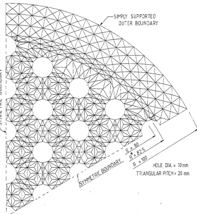
The perforated regions of the tubesheets are modeled as equivalent solid plates having same geometrical dimensions except for the absence of holes but with the modified elastic constants. The effective elastic constants are isotropic in the plane of the plate. The effective elastic modulus ratio in the thickness direction E/ E will be equal to the ratio of solid material area to the total area and the effective Poisson's ratio in the thickness direction is equal to the Poisson's ratio of the solid material (ν=ν). These relations are valid for all penetration patterns [3]. In Annexure A17 of RCC-MR [4], the above concept of having one set of elastic constants for the plane of the plate and another for the thickness direction is included. Further, it also has included treatment for a perforated plate with circumferential pitch. Accordingly we have E* / E = 0.2 and ν* = 0.41 for the plane of the plate and E / E =
various equivalent plate models. Based on the comparison of deflection behaviour of various models (Fig. 3), it is demonstrated that the anisotropic analysis as per RCC-MR is more realistic. There are 3600 tubes arranged in 25 concentric rows. The tubes of each row are modeled into an equivalent shell simulating axial and rotational stiffness offered by the tubes. The equivalent shell is modeled using 'COQU' elements of CASTEM 2000. The length of the equivalent shell is taken as same as that of tube and PCD of a given row is taken as the mean diameter. The Young's modulus and thickness are modified to simulate axial and rotational stiffnesses.
Analysis
The analysis has been carried out for 150 mm thick tubesheets for steady state (Level A) and transient (Level C) pressure loadings. For the bottom tubesheet, the radial stress in the equivalent solid plate (σr) is 41.0 MPa and the
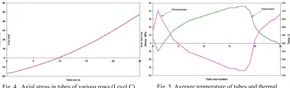
primary membrane plus bending stress intensity in the actual perforated plate is ~169 MPa which is less than the allowable value of 187 MPa. Similarly, the stress intensity in the top tubesheet is 118 MPa compared to the allowable value of 171 MPa. Thus the tubesheet stresses are found to be well within the design code limits. The axial stress distribution in the tube bundle under Level C loading is typically given in Fig.4. The outer rows of tubes are under tension and the inner rows are under compression. Typically the average temperature distribution and thermal stresses in the bundle are given in Fig.5. The investigation for buckling of inner shell and buckling and pullout strength of tubes are discussed in the following paragraphs.
BUCKLING ANALYSIS OF INNER SHELL IN THE TUBE BUNDLE REGION
This shell is subjected to longitudinal stress due to pressure and thermal loadings. For the design thickness of 16 mm, the bifurcation load is obtained using σcr = 0.605 * E * t / R. The inelasticity and ovality are accounted as per
simplified approach of Appendix: A7 [5] in RCC-MR. For an ovality of 0.5%, the allowable buckling stresses are 25.0 MPa and 31.3 MPa for Level A and Level C loadings respectively. The corresponding induced stresses are 7.2 MPa and 16.7 MPa and hence meet the limits. The allowable ∆T during thermal transients with associated pressure loading are
radius of tubesheet (mm)
0 10 20 30 40 50 60 70 80 90 100
2.00
1.75
1.25 1.50
0.75
0.50
0.25 1.00
0.00
ISO EQ. PL. ANALYSIS (QUA8) ORTHO. EQ.PL ANALYSIS (QUA8) ANISO. EQ.PL ANALYSIS (QUA8)
3-D ANALYSIS W ITH HOLES (PLATE ELEMENTW ITH SHEAR)
Fig. 3 Deflection of typical tubesheet with various models
obtained as per the procedure given in ref [6]. For a feed water trip incident (the governing transient), the induced stress under pressure loading is 5.7 MPa and the associated allowable ∆T is ~ 24 K which is higher than the design value of 22 K. For 1% ovality, the allowable ∆T is only ~ 13 K and hence the shell ovality shall be limited to 0.5% or less. STATIC STRENGTH OF TUBES
Buckling analysis for tubes
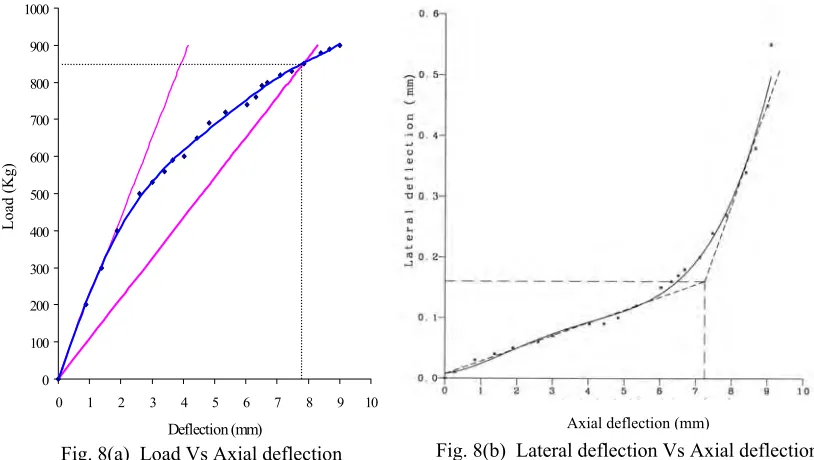
The tube bundle has nonclassical intermediate supports (Fig.6) with belts and ferrules. The buckling strength of tube with multiple span has been determined based on tests. The experimental setup (Fig.7) simulates the actual intermediate support and also the tubesheets at both ends. The load, axial deflection, lateral deflection and strain measurements are made in various spans.
The load deflection curve and a plot of lateral deflection Vs axial deflection are shown in Fig. 8. The critical axial displacement obtained by experiments (minimum value) is 7 mm and the minimum critical buckling load is ~ 850 Kg (2-slope method). This corresponds to a buckling stress of ~115 MPa. The Euler stress obtained by treating the tested tube as a continuous beam is 259 MPa. The corresponding buckling stress after accounting for the imperfection and plasticity as per the simplified approach of Appendix: A7 is ~110 MPa which is very close to the experimental value and hence the simplified approach is followed for PFBR IHX.
For PFBR IHX, the Euler stress is obtained by treating the tube as a continuous beam with variable spans. The extreme ends of the tubes are treated as clamped and the intermediate supports as simply supported. A maximum deviation of 1.0 mm in any span for the built in exchanger is considered. With the design temperature of 798 K, the load
Fig. 6 Non classical intermediate support Fig. 7 Experimental setup
Axial deflection (mm)
Fig. 8(b) Lateral deflection Vs Axial deflection Fig. 8(a) Load Vs Axial deflection
0 100 200 300 400 500 600 700 800 900 1000
0 1 2 3 4 5 6 7 8 9 10
Deflection (mm)
Load (Kg)
controlled buckling limit for the tube span of 675 mm is 24.6 MPa for the Level A loadings. The allowable limits are 1.25 times higher for Level C loadings in accordance with RCC-MR. The corresponding induced stresses are 6.9 MPa and 15.9 MPa and hence meet the limits. The allowable ∆T during thermal transients is also obtained for the tube using the similar procedure followed for the inner shell [6]. For a feed water trip incident (the governing transient), the induced stress under pressure loading is 5.4 MPa and the associated allowable ∆T is ~ 25 K which is higher than the design value of 22 K for the compressive stress. Hence buckling limits are met under normal operation and transient conditions.
Analysis for pullout strength of tube to tubesheet joint In order to evaluate the high temperature strength of tube to tubesheet joint, detailed experimental investigation has been carried out (Fig.9). Totally 12 tests have been completed (7 without relaxation and 5 with simulated relaxation). The accelerated tests have been conducted based on Larson Muller parameter of 20 for the austenitic material. Thus loading at 823 K for 40 calendar years with 75 % capacity factor is equivalent to carrying tests at 930 K for 168 h. All the tests indicated that the rolled and welded joint is stronger than the basic strength of the tube material. Hence the strength of the tube decides the allowable value for mechanical loading. However, the allowable tensile strength of the joint under mechanical loading is 0.95 times the allowable value as per
ASME [7], and also the allowable tensile strength of the joint under mechanical plus thermal loading is twice the allowable value for mechanical loading. Based on the above guidelines of ASME and test results, the allowable values for various loadings have been arrived at. The induced longitudinal stresses are 22.5 MPa during normal operation and 50 MPa during LSWR (level C) which are found to meet the limits. During feed water trip, the pressure stress is 18.0 MPa and the associated allowable ∆T (so as to limit the total longitudinal stress to the allowable value of 125 MPa) is -36 K, which is greater than the design value of -26 K (for tensile stress).
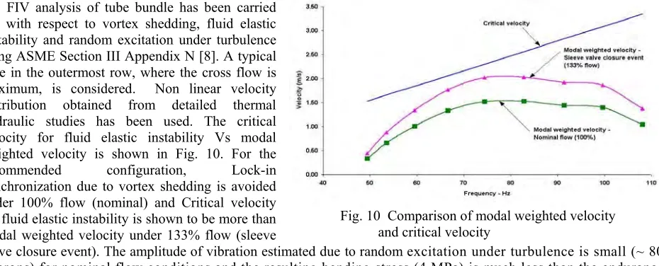
ANALYSIS FOR FIV MECHANISMS
FIV analysis of tube bundle has been carried out with respect to vortex shedding, fluid elastic instability and random excitation under turbulence using ASME Section III Appendix N [8]. A typical tube in the outermost row, where the cross flow is maximum, is considered. Non linear velocity distribution obtained from detailed thermal hydraulic studies has been used. The critical velocity for fluid elastic instability Vs modal weighted velocity is shown in Fig. 10. For the
recommended configuration, Lock-in
synchronization due to vortex shedding is avoided under 100% flow (nominal) and Critical velocity for fluid elastic instability is shown to be more than modal weighted velocity under 133% flow (sleeve
valve closure event). The amplitude of vibration estimated due to random excitation under turbulence is small (~ 80 microns) for nominal flow conditions and the resulting bending stress (4 MPa) is much less than the endurance limit.
In the sector model of support (Fig. 6), the hooping effects of belts are achieved by tightening the bolts at either end and there is fear of loosening of supports under fretting wear (due to vibration) and under creep. The effect of loosening of belt on the boundary condition is obtained by modal hammer tests using the setup shown in Fig.7. The natural frequency of tube measured with full tight belts is 109 Hz. The experiment is repeated with varying tightness of belt. The natural frequency shifted as expected but at the worst case (full loosening) also, the supports behaved slightly better than simply supported boundary condition. The natural frequency measured (106 Hz) was always higher than the theoretical value corresponding to simply supported condition at the intermediate supports (100 Hz). Further, the experiments were carried out on 60 degree sector model (φ 24 X 1 WT tubes) using water as fluid. Tests were carried
Fig. 9 Pullout strength of tube to tubesheet joint
out upto 70% higher flow than the nominal flow. No unknown source of FIV mechanism was found to exist. The tests have also confirmed the absence of vortex shedding or fluid elastic instability and increased the confidence on the analysis for the type of non classical support used in the bundle.
ANALYSIS FOR SEISMIC LOADING
Seismic analysis of IHX has been carried out using response spectrum method corresponding to OBE and SSE seismic loading. FRS at IHX support is used as input spectrum. FE model was prepared using beam, mass, spring and rigid elements and its Spread-out view is shown in Fig. 11. Tube bundle has been replaced by means of four equivalent beams. The equivalence in cross sectional area and moment of inertia (MI) is maintained. The responses (displacement and stresses) are determined using natural modal data obtained from the natural frequency analysis. Fig.12 shows fundamental mode shape (4 Hz), which is the global bending mode of IHX. The functional requirements are met, i.e. there is no mechanical interaction between internal adjacent shells as well as between IHX and IV. The maximum stress intensity due to seismic and normal pressure loading occur at the junction of hot sodium collector and top tube sheet, equal to 89 MPa and 102 MPa under OBE and SSE respectively, which are less than the corresponding RCC-MR stress limits. The tube stresses deduced from the analyses results were found to be within allowable limits. 80 numbers of M30 bolts provided at the top flange were found to meet the stress limits.
ANALYSIS FOR CDA LOADING
The structural integrity of IHX model under CDA has been ensured by the third series (TRIG -III) of experiments on reactor assembly models with internals and details are presented in a companion paper [9]. TRIG-III tests are on 1/13th scaled down mockups which have all the essential features of prototype
geometry. Five tests were conducted on TRIG-III mockups with 22 g LDE which simulates 110 MJ of energy release in the reactor scale which is the design requirement. IHX models in which, two outer rows of tubes and various shells have been simulated were used in this test series. For the tubes and shells, D/t ratios were maintained. The tubes were attached to plates used to simulate the tubesheets at either end, by flaring. It is noted from the tests that IHX are integral with negligible deformations (Fig. 13) and the integrity of IHX specifically tubes was confirmed even for 300 MJ of energy release.
The welded flange at top and the hold on loose flange in two halves and the bolts are designed for a peak cover gas pressure of 2.15 MPa during CDA loading [9]. The welded flanges and the loose flanges are modeled along with bolts in CASTEM 2000. Both flanges are modeled using axisymmetric QUA8 elements. The bolts are modeled as an equivalent axisymmetric shell simulating
only the axial rigidity. The deformation and stress limits of the bolted flange assembly were found to be within the allowable values for the CDA loadings.
CONCLUSION
IHX has been analysed using detailed FEM model incorporating anisotropic equivalent solid plate model of tubesheets, axial and rotational rigidity offered by the tubes. In case of anisotropic analysis, the compressive stresses in the inner shell and in the tubes of innermost row are found to be more than the values obtained from isotropic analysis. Hence it is essential to use more accurate anisotropic model proposed in RCC-MR. The accuracy of anisotropic model is also demonstrated using 3-D analysis on actual perforated model of a validation problem.
Based on the theoretical and experimental investigations of buckling and pullout strength of tubes, the contribution of straight tubes in sharing the mechanical loads (loads due to differential pressure on tubesheets and load due to pressure on bottom dished end) has been realistically estimated and accordingly, the allowable ∆T during thermal transients have been established. The design ∆T values deduced from thermal hydraulic studies were found to be within the above allowable limits. By analysis and model studies, it is demonstrated that the tube bundle is free from FIV risks. The structural integrity of IHX under seismic loading has been ensured by analysis. The integrity of IHX specifically tubes under CDA loadings was confirmed by experiments even for 300 MJ of energy release. The integrity of top flange and bolts under seismic as well as CDA loadings have been confirmed by analysis.
REFERENCES
1. RCC-MR subsection NB for class 1 components, “Design and construction rules for mechanical components of FBR Nuclear Islands (RCC-MR)” AFCEN, Paris, France, 1993.
2. Selvaraj, P. et al., “Review of design basis accident for large leak sodium-water reaction for PFBR”, 4th
international conference on Nuclear Engineering, Louisiana, March 1996.
3. W. J. O' Donnell, “Introduction to Chapter on Perforated plates and shells, Pressure vessel and Piping: Design and Analysis - A Decade of progress”, Vol.2, pp.1041-1046, 1972.
4. Appendix A17 of RCC-MR, “ Equivalent solid plate analysis of tubesheets”, 1993. 5. Appendix A7 of RCC-MR, “Analysis taking account of buckling”, 1993.
6. G.Clement et al, “A practical rule for progressive buckling”, Nuclear Engineering and Design 111 (1989) 209-216 7. ASME SecVIII Div 1, “Basis for Establishing Allowable Loads for tube - tubesheet joints”, 2001.
8. ASME section III Div., Appendix: N, ‘Dynamic Analysis Methods’ 2001.
9. Chellapandi, P. et al.” Analysis for Mechanical Consequences of A Core Disruptive Accident In Prototype Fast Breeder Reactor”, Tran. 17th International Conference on Structural Mechanics in Reactor Technology, Vol. J,
Progue, Czech Republic, August 17-22, 2003.