Stacked Ring Coupled Rectangular Microstrip
Antenna with Slots
Vani R.M1, Inamdar S.R2, Prahlada Rao K3, Hunagund P.V4
Professor, University Science Instrumentation Center, Gulbarga University, Gulbarga, Karnataka, India1
Professor, Dept. of Physics, Karnatak University, Dharwad, Karnataka, India2
Research Scholar, Dept. of Applied Electronics, Gulbarga University, Gulbarga, Karnataka, India3
Professor, Dept. of Applied Electronics, Gulbarga University, Gulbarga, Karnataka, India4
ABSTRACT: This paper discusses the effect of stacking on the performance of a ring coupled rectangular microstrip patch antenna. The antennas have been designed at a frequency of 2 GHz and they have been simulated using Mentor Graphics IE3D simulation software. The substrate used in the design is FR-4 glass epoxy which has a dielectric constant of 4.2. The operating frequency range is from 1-6 GHz. The antennas have been fabricated and the measured results are compared with the simulated results. The measured results are in agreement with their counterparts. The ring coupled rectangular microstrip antenna stacked on ring coupled rectangular microstrip antenna with U-slot on ring yields the widest bandwidth of 9.635%. The ring coupled rectangular microstrip antenna stacked on ring coupled rectangular microstrip antenna with U-slot on ring and patch yields the lowest resonant frequency of 1.27 GHz; thereby producing the best size reduction of 18.862%.
KEYWORDS: Center patch, Ring Coupled, Stacking, U-Slot.
I. INTRODUCTION
Microstrip patch antennas are prominent and popular because of their advantages - light weight, planar structure and ease of integration and compatibility with monolithic microwave integrated circuits (MMIC’s). A serious limitation of these antennas is they posses narrow bandwidth. Many modern communication systems and emerging technologies require antennas with broad bandwidth compact size. New motivation to research is given to enhance the bandwidth and reduce the virtual size of the microstrip antennas [1-3].
A microstrip patch antenna basically consists of a radiating patch on one side of the dielectric substrate which has a ground plane on the other side. Conducting material such as copper or gold is used to make the radiating patch. Microstrip antennas radiate because of the fringing fields between the edges of the patch and the ground. The design of the following microstrip patch antennas have been dealt – Rectangular microstrip antenna (RMA), Ring coupled rectangular microstrip antenna (RCRMA), Ring coupled rectangular microstrip antenna stacked on Ring coupled rectangular microstrip antenna with U-slot on ring (Antenna - 1), Ring coupled rectangular microstrip antenna stacked on Ring coupled rectangular microstrip antenna with U-slot on centre patch(Antenna - 2), Ring coupled rectangular microstrip antenna stacked on Ring coupled rectangular microstrip antenna with U-slot on ring and patch(Antenna - 3).[4-9]
II. RELATED WORK
band using PIN diode as a switch. A PIN diode is incorporated in the slot etched on rectangular patch antenna. The frequency band selectivity is achieved by controlling the state of the switch inserted in the antenna. In [8] authors have designed a dual frequency dual polarized microstrip antenna fed along the diagonal, embedded with a square slot having three extended stubs for frequency tuning. Two additional stubs of the same dimensions are also incorporated at right angles to the base arm. By changing the dimensions of the base arm and stubs in a uniform manner the ratio of the operating frequencies can be lowered. In [9] a broadband high gain microstrip patch antenna using slot is proposed. The slot use on the patch’s surface affects the radiation characteristics of the proposed antenna. By using slot on rectangular patch with coaxial probe feed a wide bandwidth is achieved.
III.DESIGNOFANTENNAS
A. RECTANGULAR MICROSTRIP ANTENNA.
Fig. 1 depicts the schematic of rectangular microstrip antenna.
Fig. 1. Rectangular microstrip antenna.
Table 1 depicts the design parameters of rectangular microstrip antenna.
Table 1: Design parameters of Rectangular microstrip antenna.
Parameter name Value
Substrate thickness 1.6mm Dielectric constant 4.2 Design frequency 2 GHz Loss tangent 0.0245 Length of the patch 46.5mm Width of the patch 36.2mm Length of the feed 18.8mm Width of the feed 3.324m Length of the quarter wave
transformer
18.8mm
Width of the quarter wave transformer
B. RING COUPLED RECTANGULAR MICROSTRIP ANTENNA.
Fig. 2 depicts the schematic of ring coupled rectangular microstrip antenna.
Fig. 2. Ring coupled rectangular microstrip antenna.
The length and width of the outer ring are equal to 21.11mm and 17.41mm.The length and width of the inner ring are equal to 15.21mm and 11.41mm.The other dimensions of the antenna are same as that of the conventional antenna.
C. RING COUPLED RECTANGULAR MICROSTRIP ANTENNA STACKED ON RING COUPLED RECTANGULAR MICROSTRIP ANTENNA WITH U-SLOT ON RING (ANTENNA -1).
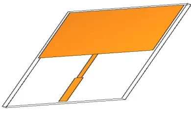
Fig.3 depicts the schematic of ring coupled rectangular microstrip antenna stacked on ring coupled rectangular microstrip antenna with U-slot on ring.
Fig. 3. Ring coupled rectangular microstrip antenna stacked on Ring coupled rectangular microstrip antenna with U-slot on ring (RCRMAUR-RCRMA).
In this configuration, ring coupled rectangular microstrip antenna with U-slot on ring is the bottom antenna and ring coupled rectangular microstrip antenna is the parasitic element placed on top of the bottom antenna. The length and width of the left and right parts of the U-slot on ring are equal to 35.2mm and 0.5mm.The dimensions of the centre part of the U-slot are 45.2mm×0.5mm.The left and right parts of the U-slot are at a distance of 3.5mm from the sides of the rectangular patch.
D. RING COUPLED RECTANGULAR MICROSTRIP ANTENNA STACKED ON RING COUPLED RECTANGULAR MICROSTRIP ANTENNA WITH U-SLOT ON PATCH (ANTENNA -2).
In this configuration, ring coupled rectangular microstrip antenna with U-slot on centre patch is the bottom antenna and ring coupled rectangular microstrip antenna is the parasitic element placed on top of the bottom antenna. The length and width of the left part and right part of the U-slot on patch are 10.41mm and 0.5mm.The dimensions of the centre part of the U-slot are 14.21mm×0.5mm.
E. RING COUPLED RECTANGULAR MICROSTRIP ANTENNA STACKED ON RING COUPLED
RECTANGULAR MICROSTRIP ANTENNA WITH U-SLOT ON RING AND PATCH (ANTENNA -3).
Fig. 5 depicts the schematic of ring coupled rectangular microstrip antenna stacked on ring coupled rectangular microstrip antenna with U-slot on ring and patch.
Fig. 5. Ring coupled rectangular microstrip antenna stacked on Ring coupled rectangular microstrip antenna with U-slot on ring and patch (RCRMAURP-RCRMA).
In this configuration, ring coupled rectangular microstrip antenna with U-slot on patch and ring is the bottom antenna and ring coupled rectangular microstrip antenna is the parasitic element placed on top of the bottom antenna. The length and width of the left part and right part of the U-slot on patch are 10.41mm and 0.5mm.The dimensions of the centre part of the U-slot are 14.21mm×0.5mm. The length and width of the left and right parts of the U-slot on ring are equal to 35.2mm and 0.5mm.The dimensions of the centre part of the U-slot are 45.2mm×0.5mm.The left and right parts of the U-slot are at a distance of 3.5mm from the sides of the rectangular patch.
IV. FABRICATED ANTENNAS AND RESULTS
Fig. 6, 7, 8 and 9 depict the photographs of the fabricated antennas.
Fig. 7. Photograph of the fabricated Antenna – 1 (RCRMAUR- RCRMA).
Fig. 8. Photograph of the fabricated Antenna – 2 (RCRMAUP- RCRMA).
Fig. 9. Photograph of the fabricated Antenna - 3 (RCRMAURP- RCRMA).
The various characteristics of the antennas designed in section 2 are studied. The simulated and measured return loss characteristics of the above mentioned antennas are shown in Fig. 10, 11, 12, 13 and 14 respectively. The values of resonant frequency, return loss and bandwidth are calculated using these figures.
1 2 3 4 5 6
-40 -35 -30 -25 -20 -15 -10 -5 0
R
e
tu
rn
L
o
s
s
[
G
H
z
]
Frequency [GHz]
Fig. 11. Plot of return loss versus frequency of RCRMA.
The antenna RCRMA is resonating at the fundamental frequency of 1.575 GHz with return loss of -12.18 dB. Harmonic frequencies are obtained at 2.93 and 3.539 GHz. Measured bandwidth at the fundamental frequency is 40 MHz. The overall bandwidth percentage is 6.35%.
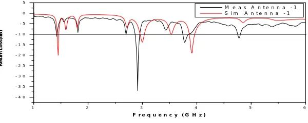
Fig. 12. Plot of return loss versus frequency of Antenna – 1.
Fig. 12 depicts that antenna -1 is resonating at 1.42, 2.91, 3.77 and 4.78 GHz respectively. The bandwidths measured are 30, 90, 120 and 60 MHz. The antenna – 1 yields an overall bandwidth of 9.635%.
Fig. 13. Plot of return loss versus frequency of Antenna - 2.
From Fig. 13, antenna-2 is resonating at four frequencies 1.43, 2.69 and 3.22 GHz respectively. The return loss at the fundamental resonant frequency is -10.8 dB yielding an overall bandwidth of 8.194 %.
1 2 3 4 5 6
-35 -30 -25 -20 -15 -10 -5 0 R e tu rn L o s s [ d B ] Frequency [GHz]
% Sim. RCRMA % Meas. RCRMA
1 2 3 4 5 6
- 4 0 - 3 5 - 3 0 - 2 5 - 2 0 - 1 5 - 1 0 - 5 0 5 R e tu rn L o s s (d B )
F r e q u e n c y ( G H z )
M e a s A n t e n n a - 1 S i m A n t e n n a - 1
1 2 3 4 5 6
- 2 0 - 1 8 - 1 6 - 1 4 - 1 2 - 1 0 - 8 - 6 - 4 - 2 0 R e tu rn L o s s [ d B]
F r e q u e n c y [ G H z ]
Fig. 14. Plot of return loss versus frequency of Antenna - 3.
Fig. 14 shows that the fundamental resonant frequency of antenna -3 is 1.277 GHz. The harmonics are at 2.129, 2.262, 2.836 and 4.035 GHz respectively. The bandwidths measured at these frequencies are 14, 22, 44, 65 and 87 MHz respectively. The overall bandwidth is equal to 8.521%.
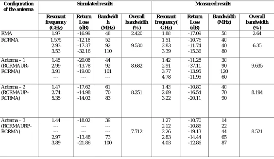
Table 2 summarizes the simulated and measured results and table 3 the measured results of size reduction.
Table 2: Simulated and measured results.
1 2 3 4 5 6
- 2 5 - 2 0 - 1 5 - 1 0 - 5 0 R e tu rn L o s s (d B )
F r e q u e n c y ( G H z )
M e a s A n t e n n a - 3 S i m A n t e n n a - 3
Configuration of the antenna
Simulated results Measured results
Resonant frequency (GHz) Return Loss (dB) Bandwidt h (MHz) Overall bandwidth (%) Resonant frequency( GHz) Return Loss (dB) Bandwidth (MHz) Overall bandwidth (%)
RMA 1.97 -16.99 48 2.420 1.88 -17.09 50 2.64
RCRMA 1.575 2.93 3.53 -12.18 -17.37 -32.16 52 92 110 9.530 1.51 2.83 3.39 -10.76 -11.74 -15.36 40 40 80 6.35
Antenna – 1 (RCRMAUR– RCRMA) 1.45 2.99 3.91 --- -20.08 -13.78 -19.00 --- 44 92 101 --- 8.682 1.42 2.91 3.77 4.78 -11.28 -37.11 -13.95 -11.95 30 90 120 60 9.635
Antenna – 2 (RCRMAUP– RCRMA) 1.47 2.74 5.35 -17.62 -14.98 -14.02 61 70 83 8.251 1.43 2.69 3.22 -10.80 -16.54 -20.11 40 70 90 8.194
resonant frequency. Among the five antennas, ring coupled rectangular microstrip antenna stacked on ring coupled rectangular microstrip antenna with U-slot on ring provides the best results in terms of bandwidth of 9.635%. From figures 10 and 11, rectangular microstrip antenna and ring coupled rectangular microstrip antenna are resonating at frequencies of 1.88 and 1.51GHz respectively. The virtual size reduction yielded by antenna-3 is 18.862%, highest compared to other designed antennas.
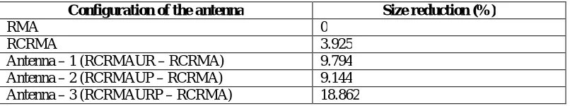
Table 3: Measured results of size reduction.
Configuration of the antenna Size reduction (%)
RMA 0
RCRMA 3.925
Antenna – 1 (RCRMAUR – RCRMA) 9.794 Antenna – 2 (RCRMAUP – RCRMA) 9.144 Antenna – 3 (RCRMAURP – RCRMA) 18.862
The results discussed above can be justified as below. With the introduction of U-slot, the length of the current path increases thereby causing a decrease in the resonant frequency, which results in the virtual decrease in the size of the antenna. Combination of U-slot, ring coupled rectangular microstrip antenna and stacking produce multiple resonances which leads to increase in overall bandwidth.
V. CONCLUSION
The above mentioned antennas have been designed and fabricated at a frequency of 2GHz with a good return loss. The antennas have been compared on various parameters to judge their performance. The results depict that the introduction of ring coupling and U- slot results in the decrease of resonant frequency of the antenna and subsequently causes size reduction. Wide band and multiple band responses have been demonstrated using the technique of stacking .The bandwidth of the conventional microstrip antenna has been enhanced by 7%. A minimum of three resonances have been obtained. As a result the performance of the conventional microstrip antenna has been improved. The results obtained satisfy the needs of wireless communications.
REFERENCES
[1] Constantine A Balanis; Antenna Theory, Analysis and Design, John Wiley & Sons Inc 2nd edition.1997. [2] I. J. Bahl and P. Bhartia, Microstrip Antennas, Artech House, 1980.
[3] Bhunia S, “Effects of Slot Loading on Microstrip Patch Antennas”, International Journal of Wired and Wireless Communications, Vol.1, Issue 01, October, 2012.
[4] P. V. Subbaiah and R. S. Rao; Antennas and Wave Propagation.
[5] Prof James Scott; Lecture notes of EEET1071/1127 Microwave and Wireless Passive Circuit Design.
[6] Murli Manohar, S. K. Behera and P. K. Sahu, “Design of Single Feed Dual Polarized and Dual Frequency Rectangular Patch Antenna” , 5th International Conference on Microwave, Antenna, Propagation and Remote Sensing, 2009 .
[7] Akanksha Tandon, B.R.Dutta and Yogesh K.Bhumia, “Design and Simulation of a Tunable Frequency Microstrip Patch Antenna” ,International Journal of Research in Engineering and Technology, Vol.12, Issue. 12, pp. 805-808, Dec 2013.
[8] G.S. Binoy, C. K. Aanandan, K. Vasudevan, and P. Mohanan, “Dual Frequency dual polarized slot-coupled compact microstrip antenna for communication systems”, International Journal of Electronics, Vol 89, Issue 03,pp.191-195.
[9] Sharad Mishra and Omesh Singh Hada, “Broadband Microstrip Patch Antenna Using Slot”, International Journal of Computer Applications, Vol 108, Issue 06, December 2014.
BIOGRAPHY
workshops and symposiums for the benefit of university faculty and PG students. Her areas of interest are microwave antennas, compact and broadband antennas, Embedded controllers and Wireless communication. She has completed one UGC major research project.
Inamdar S.R received his B. Sc and M. Sc Physics in the year 1981 and 1983. He has received his Ph. D in the year 1990. Currently he is working as Professor in the department of Physics, Karnatak University, Dharwad, Karnataka. He has 50 research publications in National/International reputed journals. He has presented more than 65 research papers in National/International conferences. He has guided many Ph.D and M.Phil students. He has completed 7 major research projects funded by UGC, CSIR and BRNS.
Prahlada Rao K received his M.E from RMIT University, Australia and B.E from Osmania University, India. Currently he is pursuing his Ph. D in the field of microwave antennas from the department of Applied Electronics, Gulbarga University, Gulbarga. He has 3 research publications in international conferences and 1 in international journal. His areas of research interests include Microstrip patch antennas and arrays, Electromagnetic Band Gap Structures, Defective Ground Structures