c
Owned by the authors, published by EDP Sciences, 2015
Experimental investigation of bond strength under high loading rates
Mathias Michal1,a, Manfred Keuser1, George Solomos2, Marco Peroni2, Martin Larcher2, and Beatriz Esteban1 1Universit¨at der Bundeswehr M¨unchen, Werner-Heisenberg-Weg 39, 85577 Neubiberg, Germany
2European Commission – Joint Research Centre, Via E. Fermi 2749, 21027 Ispra (VA), Italy
Abstract. The structural behaviour of reinforced concrete is governed significantly by the transmission of forces between steel and concrete. The bond is of special importance for the overlapping joint and anchoring of the reinforcement, where rigid bond is required. It also plays an important role in the rotational capacity of plastic hinges, where a ductile bond behaviour is preferable. Similar to the mechanical properties of concrete and steel also the characteristics of their interaction changes with the velocity of the applied loading. For smooth steel bars with its main bond mechanisms of adhesion and friction, nearly no influence of loading rate is reported in literature. In contrast, a high rate dependence can be found for the nowadays mainly used deformed bars. For mechanical interlock, where ribs of the reinforcing steel are bracing concrete material surrounding the bar, one reason can be assumed to be in direct connection with the increase of concrete compressive strength. For splitting failure of bond, characterized by the concrete tensile strength, an even higher dynamic increase is observed. For the design of Structures exposed to blast or impact loading the knowledge of a rate dependent bond stress-slip relationship is required to consider safety and economical aspects at the same time. The bond behaviour of reinforced concrete has been investigated with different experimental methods at the University of the Bundeswehr Munich (UniBw) and the Joint Research Centre (JRC) in Ispra. Both static and dynamic tests have been carried out, where innovative experimental apparatuses have been used. The bond stress-slip relationship and maximum pull-out-forces for varying diameter of the bar, concrete compressive strength and loading rates have been obtained. It is expected that these experimental results will contribute to a better understanding of the rate dependent bond behaviour and will serve for calibration of numerical models.
1. Introduction
1.1. Bond between steel and concrete
For reinforced concrete structures under blast and impact not only the rate dependence of steel and concrete influences the structural behaviour. Their interaction determines significantly the structural response under static and dynamic loading. The transfer of forces between steel and concrete is always connected to a relative displacement. Already after a slight displacement the chemical adhesion is overcome and the main mechanism of bond, the mechanical interlock is activated. Thereby the ribs of the reinforcement are bracing concrete consoles in the concrete surrounding the steel. After shearing of the concrete consoles, only the frictional resistance remains for the transmission of forces. The bond stress is defined as the evenly over the circumference of the bar distributed force that is transferred between steel and concrete. For the description of bond the bond stress is related to the slip (Fig.1). While for static loading with small deformation the assumption of a rigid bond mostly leads to satisfactory results, this can cause a wrong judgement of the structural behaviour under dynamic loading.
Only limited research has been done on bond under high loading rates in the past [1–6]. An overview is given in [7]. The same parameter influencing the static bond conditions are valid for bond behaviour under high loading rates. Some of them are of particular importance for the
aCorresponding author:[email protected]
increase of dynamic bond strength as compared to static behaviour. With increasing concrete compressive strength a decreasing rate dependence of bond strength has been observed. Another parameter is given with the geometry
of the ribs. In the majority of the reviewed research there
seems to be no significant influence of loading rate for plain bars, the bond resistance of deformed bars increases with higher loading rates. The stress distribution under dynamic loading is more concentrated. With increasing
bond length, the rate dependence decreases. Localized
cracks due to concentrated transfer of bond stress for faster rate loading can lead to a brittle failure of structures showing a ductile behaviour under static loading. The spatial stress condition in the concrete leads to circular tensile forces, this can result in a change of the failure type from pull-out of the bar to splitting of the concrete cover. Tests showed increased ultimate loads under dynamic loading for specimens failing by pull-out but a higher dynamic increase for specimens failing by splitting. Only for a short loading duration the increase of bond strength can result in higher load bearing capacity. With increasing load duration the bond strength decreases.
1.2. Hopkinson Bar Technique
The Split-Hopkinson-Bar (SHB) is often used to determine the uniaxial material properties for medium strain rates. The theory of the method can be found in [8–11]. Thereby the specimen is sandwiched between an incident and an output bar (Fig. 2). With a loading device a stress wave
Figure 1. Idealized bond-slip-relationship [7].
Figure 2. Schematic test configuration SHB.
is induced in the incident bar. At the interface between bar and specimen the wave is partly reflected and partly transmitted to the specimen. This process is repeated at the transition to the output-bar and leads to multiple reflection in the specimen. If the time the wave needs to pass through the specimen is essential short compared to its temporal extension, a uniform stress and strain distribution is assumed and the well known formulae for the analysis of the SHB-Test based on the propagation of a one-dimensional wave can be used.
The displacement of the initial (uA) and end (u)
cross-section of the specimen is obtained by integrating the particle velocity vp(1)(2).
uA(t)= t
0
vp,A(t)dt =C0,Bar t
0
[εI(t)−εR(t)] dt
(1)
u(t)=
t
0
vp,(t)dt =C0,Bar t
0
εT(t)dt. (2)
Using the difference of the displacements and the original length of the specimen, the strain and thereby the strain rate and stress in the specimen can be calculated.
For the bond tests modified configurations of the Split-Hopkinson-Bar have been applied.
2. Rebar pull-out tests
Pull-out tests have been performed by employing Hopkinson bar techniques at the JRC in Ispra [6]. Confined and unconfined cylindrical specimens with a diameter of 100 mm and bars with ds=20 mm have been tested. The
length of the specimen varied with the embedment length (lb=100 mm=5 ds, 200 mm=10 ds). A bond breaker
of length 50 mm has been incorporated on both ends. These parts have been subdivided into three equal sectors.
Figure 3. (a) Principle of functioning of the JRC modified
Hopkinson bar; (b) details of mounting of the rebar specimen in the inversion canister between the incident and transmitter bar [6].
The specimens have been manufactured in two concrete compressive strengths (C25/30, C50/60).
An incident strain pulse was generated by pre-stressing and abruptly releasing a long bar, which was the contin-uation of the incident bar. The diameter of the incident bar was 72 mm and its length approximately 8 m. A 1.1 m long steel inversion canister, housing the specimen, was connected to its end (Fig. 3). The transmitter bar of diameter 25 mm and length 50 m was connected by a collar to the rebar of the specimen. The pull-out Force was measured by a strain gauge at the output bar and the displacement (slip) was referred to the interface point rebar/concrete at the front part of the specimen (point A).
The specimens confined by a steel tube with wall-thickness of 10 mm failed by pull-out. Due to the small concrete cover of 2.5·ds the unconfined specimens failed
by splitting of the concrete. While bond strength increased for C50/60 under high rate loading, the increase has been higher for the C25/30 specimens (Fig.4). The increase of ultimate bond strength for doubling the embedment length under dynamic loading was lower compared to the increase under static loading. A detailed description of the tests and further results can be found in [6].
3. Rebar push-in tests
In a current research project, funded by the Federal Ministry of Economics and Technology (BMWi) the bond behaviour between steel and concrete is investigated. In collaboration between the University of the Bundeswehr and the Fraunhofer Ernst-Mach-Institute (EMI) push-in tests are performed using a Split-Hopkinson-Bar.
The push-in specimen is installed between the incident and the output bar (Fig. 5). The length of the incident bar is 5 m, that of the output bar 3.5 m and their diameter 75 mm. The bars and the transition cylinders are made of aluminium.
75% 100% 125% 150% 175% 200% 225% C25/30 lb = 5 ds pull-out
C25/30 lb = 5 ds spling
C25/30 lb = 10 ds
pull-out
C25/30 lb = 10 ds
spling
C50/60 lb = 5 ds spling es ae rc ni ci ma ny d
Figure 4. DIF for different concrete compressive strengths, bond
lengths and failure mechanisms in [6].
Figure 5. Schematic push-in test SHB configuration.
between specimen and output bar. With specially drilled holes and a mirror it is possible to measure the translation of the bar with a vibrometer. The slip is determined by the difference of the signal given by the vibrometer and the overall displacement of the specimen calculated with formula (2) from the time-shifted signal of the strain gauge mounted on the output bar. The dispersion in the bar has been considered with a VBA-Routine based on the method described in [8,10–12].
The wave is separated in its frequency components using Fourier transformation (formulas 3–9).
f (t)=a0
2 +
∞
n=1
dn·cos (nω0t−n) (3)
n =ar ctan (bn/an) phase angle (4)
ω0=2π/T angular f r equency. (5)
Fourier coefficients:
a0=
2
T
T/2
−T/2
f (t)dt (6)
an =
2
T
T/2
−T/2
f (t)·cos(nω0t )dt f or n≥1 (7)
-0,2 0 0,2 0,4 0,6 0,8 1 1,2 1,4
1,44 1,48 1,52 1,56
st
ra
in
[mm/m]
me [ms] recorded gauge 2 gauge 4 shied gauge 4 corrected
-0,2 0 0,2 0,4 0,6 0,8 1 1,2 1,4
2 2,04 2,08 2,12 2,16
st
ra
in
[mm/m]
me [ms]
recorded gauge 4 gauge 2 shied gauge 2 corrected
Figure 6. Backwards (left) and forwards (right) time-shifted and
dispersion corrected signalsx=3 m, C0=5211 m/s.
bn =
2
T
T/2
−T/2
f (t)·sin(nω0t )dt f or n≥1 (8)
dn =
a2
n +b2n. (9)
The phase velocity of the n-th frequency is determined by a numerical iteration. A wave lengthn,iis assumed and the
phase velocity Cn,i is calculated with formula (10). With
the interpolated phase velocity given by the table in [10] the wave lengthn,jcan be calculated again using formula
(10). If Cn,i and Cn,j doesn’t show sufficient agreement
(e.g. Cn/1000), the calculation process is repeated with
a mean wave length n,k=0.5·(n,i+n,j). With the
known wave velocity the phase angle difference to the phase angle without dispersion can be calculated with formula (11), where x is the distance over which the signal is shiftet.
Cn,i =
n·ω0·n,i
2·π =
n·n,i
T (10)
dn=n·ω0·
x Cn
−x
C0
· (11)
The new wave can be constructed with formula (12). In this study a number of 100 Fourier components has been chosen.
f (t)= a0
2 +
∞
n=1
dn·cos [nω0t−(n +dn)]. (12)
In the described procedure only the first mode vibration of the Pochhammer-Chree analysis is considered, but Fig.6 shows the good agreement of the time-shifted, dispersion-corrected signal with the recorded signal.
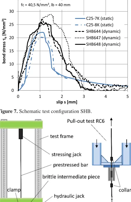
In addition the displacement of the transition cylinder, used for load transfer to the reinforcement bar, and the specimen has been measured by an optical measuring device. Both methods showed good agreement. The transferred force is obtained from the strain gauge on the output bar. After a time-shift of the force, the bond-slip diagram could be drawn (Fig.7).
0 5 10 15 20 25 30 35
0 1 2 3 4 5
bo
n
d
s
tress
ττb
[N
/mm²
]
slip s [mm]
C25-7K (stac) C25-8K (stac)
SHB644 (dynamic) SHB647 (dynamic) SHB648 (dynamic) fc = 40,5 N/mm², lb = 40 mm
Figure 7. Schematic test configuration SHB.
Figure 8. Schematic test configuration.
rate-dependent increase in bond strength. On this basis, an extensive experimental program will be conducted as a contribution to the research on bond stress under high loading rates.
4. Development of a new test setup
4.1. Test configurationA new test setup (Fig. 8) based on the idea of Albertini [13] to induce a tensile wave by abruptly releasing the elastic mechanical energy stored inside a prestressed bar has been developed at the UniBw [15]. It is planned, to use specimens based on the RILEM pull-out test (RC6) and the RILEM beam test (RC5) [14].
The procedure of the tests is as follows: A prestressing bar is blocked by static friction between the bar and two bearing shells after a horizontal force is applied. Then the vertical force can be increased until the required prestressing is achieved. The prestressed bar is a DYWIDAG threadbar type 18WR with a diameter of 17.5 mm and a nominal cross-section area of 241 mm2. The
maximum pretension force is given by the manufacturer
Figure 9. Blocking system.
with 0.9·Fp0.1k=204 kN and the nominal tensile strength
with Rm=1050 N/mm2. For the tests the pretension force
has to be within the elastic range of the material. After removing the blocking system a release wave is running through the prestressed part of the bar and a tensile wave propagates in the direction of the specimen. The length of the wave equals twice the length of the prestressed part of the bar and its amplitude is half of the prestressing.
While for the pull-out tests the induced wave runs directly through the specimen and principles of wave propagation will be used for the evaluation of the tests, there is no direct connection for the beam tests and inertia has to be considered.
A crucial part of the configuration is the brittle intermediate piece. To obtain high strain rates the preload force needs to be released abruptly. A blocking system similar to the theta-clamp, developed at the JRC [16,17] has been chosen (Fig. 9). The system consists of several elements. When the clamping force is applied, four struts are bracing against joints, held together by a brittle bolt. The force is increased up to a certain limit and the bar can be pre-tensioned. After a further increase of the force the bolt fails and the whole system collapses into pieces. This leads to a sudden release of the blocking and a steep rise of the wave. The bolts have been made of 42CrMo4 with a tensile strength of 1560 N/mm2.
4.2. Pull-out Test (RC6)
First tests are based on the configuration for the RILEM Pull-out test [14]. The specimens have been modified as the focus in these tests lies on splitting failure. For the reinforcement a DYWIDAG prestressing steel 18 WR with a diameter of 17.5 mm has been chosen. It is thus possible to directly connect the specimen with the prestressed bar of the test setup. The rebar in the cylindrical specimens with a diameter of 85.6 mm has a bond length of 70 mm=4 ds. The concrete cover is with 34.05 mm nearly 2 ds. On both ends of the concrete specimen there is a bond free length of 50 mm.
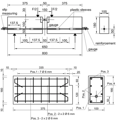
Figure 10. Specimen beam test.
Because of the small slip only a part of the wave can be transferred to the concrete. To prevent reflections, the bar is continued behind the specimen.
The static tests can be performed with the same config-uration, which improves the comparability of the results. Tests with similar specimens and the method already described in chapter 2 will be performed at the JRC. 4.3. Beam Test (RC5)
With the RILEM Beam Test [14] the situation of a reinforcement bar in a bending beam should be simulated. The specimen consists of two identical reinforced halves of a beam connected by the reinforcement for the bond test and a steel hinge for the transfer of the compressive force (Fig.10). The recommended dimensions of the specimen differ according to the diameter of the bar. For the dynamic beam test specimens with a bar diameter of 10 mm will be used.
For the static tests the bond stress can be calculated using the applied vertical load (13,14).
Fs =1,25·F (10≤ds<16 mm) (13)
τb =
Fs
π·ds·lb·
(14) In the dynamic test the pull-out force will be determined by a strain gauge mounted at mid span at the bar as due to inertia the formula used in the static test can’t be applied.
5. Conclusions and outlook
The bond between steel and concrete is essential for reinforced concrete structures. It’s based on adhesion, friction and mechanical interlock. Literature has been reviewed and static and dynamic tests on bond between steel and concrete have been performed with different
methods by the University of the Bundeswehr Munich and the Joint Research Centre in Ispra. Due to the different test methods and boundary conditions it is difficult to compare results drawn from literature. For deformed bars an increased bond strength with increasing loading rate can be noted. The rate dependent increase of concrete strength seems to be of great importance for this phenomenon but there is no knowledge from the tests of the local strain rates in the concrete. The main parameter influencing the rate dependent bond behaviour can be identified as concrete compressive strength, diameter of the bar and geometry of the ribs, bond length, failure type and load duration. To quantify them there is still a considerable need for research.
For the design of reinforced concrete structures under blast and impact the knowledge of the rate dependent bond behaviour is important. Localized cracks or a decreased rotation capacity due to the increased bond can lead to undesirable effects on structures.
Further tests will be conducted with a new developed test configuration at the UniBw and a proven method at the JRC, using similar specimens. This can lead to a better understanding and interpretation of the results obtained by the different test methods.
References
[1] R.J. Hansen, A.A. Liepings, Proc. ACI J., Vol. 59, No. 4, 563–583 (1962)
[2] H. Paschen, J. Steinert, O. Hjorth, Untersuchungen ¨uber das Verbundverhalten von Betonst¨ahlen bei Kurzzeitbeanspruchung, Tech. Rep., TU Braun-schweig (1974)
[3] E. Vos, Reinhardt H.W., Rep. 5-80-6, Delft Univ. of Tech. (1980)
[4] C. Yan, PhD Thesis, Univ. of Brit. Col. (1992) [5] J.H. Weathersby, PhD Thesis, Louisiana State Univ.
(2003)
[6] G. Solomos, M. Berra, Mat. and Struct. 43, 247–260 (2010).
[7] M. Michal, M. Keuser, in Proc. of 9th International Conference on Structural Dynamics, EURODYN 2014, Porto, Portugal (2014)
[8] R.M. Davis, Phil. Trans. of the Roy. Soc.of London, Series A, Vol. 240, No. 821, 375–457 (1948) [9] H. Kolsky, Proc. Phys. Soc. B62, 676–700 (1949) [10] D. Bancroft, Phys. Rev., 59, 588–593 (1941) [11] J.C. Gong, L.E. Malvern, D.A. Jenkins, J. of Eng.
Mat. and Tech., 112, 309–314 (1990)
[12] S. Zheng, Dissertation, University Karlsruhe (1996)
[13] C. Albertini, M. Montagnani, in Proc. of the Conference on Mechanical Properties at High Rates of Strain, Oxford (1974)
[14] RILEM, Rec. for the Testing and Use of Constr. Materials, E & FN Spon, London (1994)
[15] M. Michal, Dissertation, University of the Bun-deswehr Munich (to be published)
[16] C. Albertini, E. Cadoni, G. Solomos, Phil. Trans. R. Soc. A 372: 20130197 (2013)
![Figure 1. Idealized bond-slip-relationship [7].](https://thumb-us.123doks.com/thumbv2/123dok_us/8175629.1365403/2.595.310.537.72.250/figure-idealized-bond-slip-relationship.webp)
![Figure 4. DIF for different concrete compressive strengths, bondlengths and failure mechanisms in [6].](https://thumb-us.123doks.com/thumbv2/123dok_us/8175629.1365403/3.595.60.284.70.297/figure-different-concrete-compressive-strengths-bondlengths-failure-mechanisms.webp)