VMCrypt - Modular Software Architecture for
Scalable Secure Computation
Lior Malka
∗Jonathan Katz
†Abstract
Garbled circuits play a key role in secure computation. Unlike previous work, which focused mainly on efficiency and automation aspects of secure computation, in this paper we focus on software modularity and scalability, considering very large circuits. Our main contribution is a virtual machine that dynami-cally loads hardware descriptions into memory and destructs them as soon as they are done computing. Our software also introduces a new technique for parallel evaluation of garbled circuits. The software is designed in a completely modular fashion, allowing developers to integrate garbled circuits through an API (Abstract Programming Interface), without having to modify the base code. We measure the performance of this architecture on several circuits with hundreds of millions of gates. To the best of our knowledge, these are the largest scalable secure computations done to date.
1
Introduction
Secure computation is a fundamental task in modern systems as it enables parties to collaborate while keeping their information private. Specifically, a two-party protocol for secure computation allows a server (holding inputx) and a client (holding inputy) to compute f(x, y) such that either party learns nothing beyond the output off. Secure computation has been studied mainly from a theoretical perspective, but in the last few years it has been utilized for implementing real world systems. Examples include implementations of systems for privacy-preserving face recognition [7, 26, 22], fingerprint matching [1, 8], and DNA processing [13].
Yao’s Garbled Circuits Technique [29] plays a key role in the construction of secure protocols. In this approach, the parties first prepare a representation of f as a boolean circuit Cf. Next, the server chooses
secret keys (called wire labels) for each wire in Cf, encrypts a a lookup table for each gate, and sends all
lookup tables, called thegarbled circuit, to the client. Thisgarblingstage is followed by an oblivious transfer protocol where the client acquires wire labels corresponding toy. The server also sends the client wire labels corresponding tox. Having obtained the wire labels forxandy, the client decrypts all lookup tables until the output gates are decrypted andf(x, y) is revealed. This is called theevaluation stage.
The garbled circuit technique has been used widely, most notably in Fairplay [19]. Fairplay introduces a high level language that allows the user to define the function f to be computed. This program is given to the Fairplay compiler, which produces a hardware descriptionCf of the boolean circuit for computingf,
and writes it into a text file. When the Fairplay client and Fairplay server are run, they readCf from the
text file and store it in memory as an objectOf. This allows them to garble and evaluate the circuit.
The main motivation for Fairplay was to show that Yao’s technique can be implemented in practice. More recently, the TASTY system [11] was proposed, which combines the benefits of homomorphic encryption with those of garbled circuits. The main motivation behind TASTY is automation of secure two-party computation. We give a more detailed discussion of previous work in Section 1.2, but we remark that the motivation here is different. Specifically, our goal is to develop a software architecture that would support very large garbled circuits (scalability) and allow developers to integrate these circuits in any application (modularity). In order to provide some measures of comparison we contrast VMCrypt with Fairplay. We
∗Intel. Work done while at the University of Maryland. Email: [email protected]
made this choice because Fairplay is based purely on garbled circuits whereas TASTY is a combination of homomorphic encryption and garbled circuits, but as we later show, the comparison applies also to TASTY.
1.1
Our Results
We present a new software architecture for scalable secure computation, called VMCrypt. Asoftware library
is code that provides services to independent programs via an abstract programming interface (API). Since VMCrypt is a library, developers can use it to integrate garbled circuits into their protocols. This enables code reusability and reduces development, debugging, and testing costs. Another difference between a library and an application is flexibility. For example, Fairplay users are restricted to a specific garbling method and a specific encryption method used in the garbling. In VMCrypt, which was designed to be customized by the application, these are defined as interfaces and passed as a parameter. Thus, a developer can pass their own implementation, or use the one provided by VMCrypt. Modularity is also important to cryptographers. VMCrypt decouples security from implementation, and in doing so it enables cryptographers to implement any level of security (e.g., semi-honest, covert, fully malicious) without changing the base code. In Fairplay, on the other hand, security is hard wired into the code. Developing libraries is hard because it requires abstracting a large system into independent modules, encapsulating these modules, and defining methods that allow them to work together regardless of underlying implementation.
The architecture of VMCrypt is completely different from that of Fairplay. In VMCrypt, circuits (called
components) are simply java classes. Hence, they receive their parameters at run time, via the constructor. In Fairplay, on the other hand, circuit parameters are passed at compile time. To see why this has serious implications in practice, consider a secure database search protocol, where the server has records ⟨xi, pi⟩,
and the client, who holds y, wants to learn all pi for which xi =y. When a VMCrypt component for this
function is instantiated, it takes three parameters: the bit length ofy, the bit length ofpi, and the size of the
database. Since these parameters are passed at run time, any table can be chosen dynamically. That is, a server using VMCrypt can run secure database queries with multiple clients on multiple tables with different sizes, all changing at run time. In contrast, a Fairplay server and client must run the Fairplay compiler every time any parameter changes. This is unrealistic, especially considering the amount of time and memory the Fairplay compiler requires. An immediate consequence of this difference is that in VMCrypt there is no offline computation phase. Protocols using VMCrypt run on the fly. Components written in VMCrypt will be complied once and for all.
The second difference between Fairplay and VMCrypt is that Fairplay executes Yao’s protocol in sequence, whereas VMCrypt executes it in parallel. Specifically, in Fairplay the server first garbles the circuit, then the client receives the garbled circuit as well as wire labels (some of which are transferred using oblivious transfer), and finally the client evaluates the garbled circuit. In VMCrypt, on the other hand, the circuit is garbled into the network stream and evaluated from it. That is, immediately after a lookup table is encrypted, it is sent to the client, who immediately decrypts and discards it. To achieve this we interleave oblivious transfer (OT) in the garbling. This is not trivial because, unlike Fairplay, where OT is executed per wire, in VMCrypt OT is done in bulk, which significantly speeds up the computation. We cover this process in detail in Section 2.
Parallelizing Yao’s protocol has far reaching implications. The first is that we have eliminated the need for storage. In real life applications, where there could be easily billions of lookup tables or wire labels, this also means that time consuming disk reads and writes are eliminated. The other implication is that the client can compute parts of the output before the server even finished garbling the circuit. For example, in our database search experiment, the client learns the output in location i(which is pi ifxi =y, and null
otherwise) throughout the protocol. In Fairplay, on the other hand, the client is idle while the server garbles the circuit, and the server is idle while the client evaluates the garbled circuit.
will crash on real life circuits. In VMCrypt, on the other hand, components require very small amounts of memory (specifically, a constant amount in the case of database search). Thus, VMCrypt makes secure com-putation scalable. What allows VMCrypt to be memory efficient is the components themselves. Intuitively, the components are like a virtual machine that loads hardware descriptions into memory when they receive input and destructs them when they are done computing. We give a detailed description of this mechanism in Section 3.
VMCrypt scales much better than Fairplay. In the case of the database function, for example, Fairplay compilation alone takes 50 seconds and 0.7 GB memory (23% of a 3 GB RAM) when the database size is 40 records. The compiler crashes after 3 minutes when the number of records is increased to 55. With VMCrypt, on the other hand, when the database size is 10,000, the entire protocol terminates after 19 seconds. Moreover, each party (and the Java virtual machine that executes it) uses only 0.15 GB memory (4.8% of 3 GB). More importantly, even when we increase the database size to 1 million (which increases the size of the circuit to 100 million gates), the parties still use the same amount of memory. We also implemented the set intersection and minimum functions. In all cases we evaluated very large circuits. This is critical because a software cannot claim to be scalable by passing only one benchmark; it needs to scale on several circuits with different structural properties. We remark that TASTY [11] showed much better performance than VMCrypt in the case of set-intersection. This is due to the technique of [9, 16], which does not use garbled circuits at all. We also remark that combining homomorphic encryption with garbled circuits yields superior performance. Detailed performance analysis is given in Section 5.
1.2
Related Work
Garbled circuits, due to Yao [29], play a key role in the study of secure computation, and as was shown recently (e.g., [17, 15, 14, 25, 24, 6]), they also have potential in practice. Other popular techniques for secure computation are based on homomorphic encryption (c.f., [23, 5, 10, 28, 27]).
Fairplay [19] was the first work to demonstrate the feasibility of two-party secure computation based on garbled circuits. The multi-party version was given in [2]. More recently, a system called TASTY was given in [11], which combines the benefits of homomorphic encryption and garbled circuits (it also incorporates many other improvements). Other works focusing on the automation and benchmarking of cryptographic protocols were given in, e.g., [3, 4, 18, 21].
The comparison provided earlier between VMCrypt and Fairplay applies also to TASTY. Specifically, since TASTY provides a high level language, it does not have an API (which means that it cannot be inte-grated in other programs) and it requires compilation (which impacts performance). In terms of scalability, TASTY does not deal with large circuits, except for one example where memory consumption climbs as the circuit reaches 4.2 million gates, and crashes thereafter. Due to the way it loads and destructs circuit descriptions, VMCrypt consistently used about 5% memory, independently of the circuit or the input size. Each of our circuits has been evaluated up to size 100 million gates, but as our tests show, we could have chosen any large number (for example, billions of gates).
2
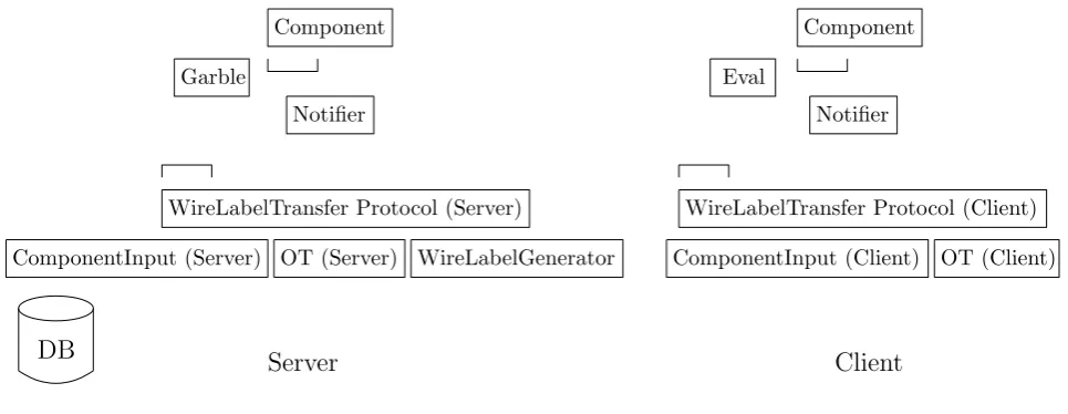
Overview of VMCrypt
This section describes VMCrypt modules, excluding components, which we discuss in the next section. We describe how the modules work when put together, but we stress that each module stands on its own.
Component
Garble
Notifier
ComponentInput (Server)
WireLabelTransfer Protocol (Server)
DB
ComponentInput (Client) OT (Server) WireLabelGenerator
WireLabelTransfer Protocol (Client)
OT (Client) Notifier
Component
Eval
Server
Client
Figure 1: Overview of main VMCrypt modules.
inputs ready. On the server side the function isGarble and the object is aWireLabelPair. On the client side the function isEval and the object isWireLabel. Both functions implement abstract classFunction.
Immediately after the notification process begins, gates receive wire label pairs on all their input wires and pass execution to the garble function. The garble function starts writing lookup tables into the network, and gates notify their output wires with a wire label pair. A symmetric process executes on the client side. That is, gates receive wire labels (as opposed to wire label pairs), the evaluation function decrypts lookup tables it receives, and gates notify their output wires with wire labels. The notifiers repeat this, segment by segment, until the entire component is notified. Immediately after the server sends the last lookup table, the client computes the output.
Oblivious transfer is not executed before or after the garbling; it is interleaved in the garbling. What makes this possible is abstract classWireLabelTransport. VMCrypt provides a server side implementation for this class calledWLTPServer(wire label transport protocol, server side) and a client side calledWLTPClient. The role of the wire label transport protocol is to guarantee that when the notifier on the server side receives a segment of wire labels, the notifier on the client side already has them. This enables the server to stream lookup tables, knowing that the client will be able to decrypt them on the fly and discard them immediately. The obvious implication of this streaming is that no storage is necessary for either wire labels or lookup tables. This is a significant advantage because the garbled circuit can be very large. Moreover, time consuming read/write operations are eliminated, thus reducing running time.
We describe the wire label transport protocol parameters, starting with the OT sub protocol. VMCrypt provides two OT implementations [20, 12], but of course any OT protocol can be passed as an argument. The second parameter is an implementation of interfaceWireLabelGenerator. The role of this interface is to provide wire label pairs for the wire label transport protocol. A standard implementation of this interface would simply return two random strings as a WireLabelPair, but VMCrypt implements the ”free XOR” idea [15] and therefore our implementation of this interface produces a pair ⟨r, r⊕R⟩, whereris a freshly chosen random string, andRis a fixed random string. To use standard garbling, all that one needs to do is provide the standard implementation forWireLabelGenerator, with the corresponding implementations of
Functionfor garbling and evaluation, and pass them as arguments to the respective classes.
(b) BinaryMIN (c) MIN
BinaryMIN BinaryMIN BinaryMIN
(a) BitMUX
MUX CMP
x y
carry
x y c
∧
Figure 2: Components of the MIN circuit due to [14, 26]
input. Implementations of CircuitInputplay another important role: if the input of the party is too large (e.g., a database) to hold in memory, thenCircuitInputcan read it from its origin segment by segment, as opposed to loading it all at once in the beginning.
The wire label transport protocol implements an OT bucket. This bucket enables executing OT in bulk, which is several orders of magnitude faster than individual OT operations. On the server side the OT bucket contains pairs of random strings ⟨rj,0, rj,1⟩. On the client side it contains one stringrj,b per pair, where
b∈ {0,1} is the client input at wire indexj. Wire labels are transferred as follows. If⟨Wi,0, Wi,1⟩is a wire label pair corresponding to a server inputb, thenWi,b is sent to the client. Otherwise,⟨Wi,0⊕r0, Wi,1⊕r1⟩
is sent, where⟨r0, r1⟩ is the pair of masks at the top of the OT bucket. This works because the wire label
transport protocol examines current and future segments to find what the client will need when future wires are reached. When the bucket is empty, the OT protocol is invoked to refill it.
3
The Component Module
The component module is the heart of VMCrypt. It has gone through four development cycles. In each cycle we evaluated performance, usability, and utility. We start with the original design and explain how it evolved to the current version.
First version. The first version of the component module was inspired by the minimum function,
which plays a central role in privacy-preserving systems [7, 26, 22, 1]. We defined two types of components:
Gate and Circuit. We also provided wires to connect them. Our idea was that developers would be able to construct small circuits, and then use them as building blocks for larger circuits. For example, a bit multiplexer (Figure 2 a) would be built in a low-level manner, from gates and wires. A string multiplexer, on the other hand, would be built from the bit multiplexer. Next, a multiplexer and a comparator can be used to build a circuit for finding the minimum of two numbers (Figure 2 b), which is then used to build a circuit for finding the minimum ofN numbers (Figure 2 c). This approach is similar to programming in
C+ + in the sense that developers have both the low-level power ofC and the modularity provided by an object-oriented language. Another advantage of this approach is that developers can share components or replace them with better implementations.
To instantiate a circuit for finding the minimum of N numbers whose bit length is arity, VMCrypt developers use the following standard Java syntax: Component c = new MIN(N, arity). The problem is that, even for modest values N = 1,000,000 and arity = 64, the number of wires needed to connect the
BinaryMINcircuits is 3∗arity∗(N−1) = 194 million wires (excluding wires and gates inside theBinaryMIN). Moreover, wires are implemented as lists (classVectorin Java) to allow fan out degree higher than 1. Thus, the memory needed to instantiate theMINcircuit is prohibitive. The code of this version was used in [8].
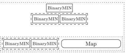
Second version. The objective of the second version was to provide components for wireless circuit
Map
BinaryMIN BinaryMIN
BinaryMIN BinaryMIN BinaryMIN
Figure 3: TheMINcomponent.
in-degree of the first sub component with the port. If the port is smaller, then the sub component receives the signal. Otherwise, the in-degree is subtracted from the port, and the switch iterates on the next sub component (of course, like all other mechanisms, this is automatically taken care of by the component and is transparent to the developer).
The switch brings up a difficult dilemma that is general to all the components. That is, should we equip a switch with output wires or not? Without output wires components will not be able to connect to each other. With them we create the same amount of wires that we wanted to eliminate in the first place. Our solution was to replace output wires of components other than gates with one pointer, and allow input wires only in circuits. Thus, gates will still be able to send signals to multiple components, but non-gate components will only be able to send signals to one component. In the rare case where this would be too restrictive, we provide a Splitter, which enables routing to multiple components. This dilemma represents a conflict between utility, usability, and efficiency, that predominated throughout the entire development process.
The other problem with the switch was that routing a signal requires linear time (as opposed to constant when using wires). This becomes quadratic per component, and increases the running time considerably. To solve this problem we introduced theUniSwitch. This component contains multiple copies of the same sub component. Thus, it can route a signal in constant time by dividing the value of the port by the in-degree of this sub component. TheUniSwitchturned out to be very useful as it enables constructing components that mimic aforloop.
Let us use these components to build the MIN component without wires. As shown in Figure 3, this component has a BinaryMIN circuit at the root, and a UniSwitch containing BinaryMIN at each layer, except the base, which is a Switch containing two sub components: aUniSwitchand a component called a Map. The map requires almost no memory as it contains nothing inside. When it receives input on port
i, it simply outputs it on port m(j), wheremis the function implemented by the map (the identity in this case). The map is used here to pass the signal one level up in case that the tree is not perfect. Notice that all the components reside inside aSwitchwhose input layer is the base layer.
Having builtMIN, let us revisit the java statementComponent c = new MIN(N, arity), which motivated all the new components in the second version. This statement no longer creates millions of wires. However, since all theBinaryMINcircuits are made of wires and gates, the MINcircuit still requires an unacceptable amount of memory.
Third version. The third version of the component module introduced the Bus. If VMCrypt has one
most important module, the bus would be it. The bus has a very simple task: it counts the number of signals leaving the component. When this number reaches zero, the bus invokes the destruct method of the component. This removes the component from memory. All VMCrypt components have a bus, except for gates, which self destruct.
Let us see how much memory the MINcomponent from Figure 3 requires now. The first signal will build the base layer, which contains two components, but only theUniSwitchwill build because theMapreceived no signal yet (assuming the signal is from the leftmost position). Inside the UniSwitch, only the leftmost
BinaryMINcircuit is built because the other ones received no inputs yet. Because theBinaryMINis also built from sub components, only those that receive this signal will be built, and so on. Eventually, the signal will hit a gate, who will store it and wait for the other signal (assuming a binary gate). When this signal arrives, the gate computes, destructs, notifies its output wire, and the process continues. When theBinaryMINfires its last output, it is destructed by its bus. In the case of a UniSwitch, even the reference to this object is removed from memory. Hence, theUniSwitchfrom the base layer becomes empty. Since each layer notifies the one above it, the Switch, which contains all these layers, requires log(N) references to components of typeUniSwitchthat are either empty or contain oneBinaryMIN. This is not a flaw in VMCrypt, but rather a consequence of the underlying recursive algorithm we are using. To further improve the notification process we added a Bufferto components of type Circuit. The buffer will build the circuit and flush only after all signals have arrived. Overall, this reduces the amount of time components (both inside and outside the circuit) reside in memory as well as the number of these components.
The notification principle confronted us with the following problem. Consider the MIN circuit from Figure 2 c. TheBinaryMin circuits (Figure 2 b) that make up this circuit take a carry bit (either 0 or 1) as input. Thus, the moment this value becomes available, all of them will be notified and hence built. The amount of memory required for this build is like having the entireMINcircuit in memory, which is clearly unacceptable. In our component for set intersection we faced the same problem. There, we have multiple copies of a sub component for set membership, and all of them are notified with the same set. The core of this problem is that ports cannot decide when to receive their notification.
Fourth version. The fourth version introducespullingandpushingports. A component with a pulling
port does not need to be connected to another component in order to receive its signals. Instead, it pulls them from a globalpulling-pushing table, calledPTable.
The most important aspect of pulling ports is that they can control when they want to be notified. For example, in the scenario mentioned above with theMINcircuit (Figure 2 c), theBinaryMincircuits will not build when the carry bit becomes available. Instead, they decide when to pull this value from the table. Of course, pulling is useless without pushing and therefore any output port can push a value into the table. In theMINcircuit scenario, for example, the carry bit will be initially pushed into the table, and components will pull it from the table.
The table presents several design challenges. Consider, for example, a component that has only pulling ports (we call it a pulling component). According to the notification principle, this component will never get notified and hence never built. The question is therefore who will notify this component and when. We decided that this will be specified by the enclosing component. That is, a component will specify its pulling ports, pulling sub components, and a counter. The component will increase its counter on each notification. When the counter reaches the in-degree of the component, all pulling ports and pulling sub-components will be notified. Thus, pulling can occur before, after, or while the component is receiving notifications. There is another issue. Recall that the role of the bus is to destruct a component once the component fired its last output. If some signals go to the PTableinstead, the bus would not know about them and therefore never destruct the component. This problem has a recursive nature because components are nested. To overcome this issue we decided that such pushing signals will continue to notify buses, but components will ignore them.
We did not conceive situations where a port pulls a value that has not been pushed yet, but to allow this flexibility the table stores references to components making such requests and notifies them as soon as the value becomes available. We decided that only components (but no other object) will push values into the table. This allows developers to exchange components with the guarantee that pulling and pushing information is built into the component.
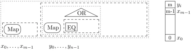
To see how a PTable works in practice, consider the VMCrypt component for set intersection from Figure 4. Intuitively, this component pushes the setX ={x1, . . . , xm−1} of the server into the table, and
Map Map EQ
y0, . . . , yn−1
OR m-1
m
0
xm−1
x0 yi
x0, . . . , xm−1
Figure 4: The set intersection component implemented in VMCrypt.
In detail, the component contains two sub components of typeUniSwitch. The first UniSwitchpushesX
into the table usingm copies of the identity map (recall that only components can push, and in this case the map is the most efficient way to do it). The second UniSwitchcontains ncopies of a Switch for set membership. This Switch contains three sub components. The first is a map that pushes yi into row m
of the table. The second is a UniSwitch that contains m copies of the equality component EQ (of type
Circuit). Thej-thEQcircuit pulls to its leftmost ports the value stored in the table at rowm(initiallyy0)
and to its rightmost ports the value stored in the table at rowj (which isxj). That is, it checks whetheryi
andxj are equal. Thus, theUniSwitchcontaining the EQcircuits outputs a sequence ofm bits that are all
0 if and only ifyi ∈/ X. Because this output is fed into anORcomponent (of typeCircuit), thei-thSwitch
for set membership will output 1 if and only ifyi ∈X.
How much memory did the PTablesave? Suppose that we compute set intersection on databases of size
N = 1,000,000 and that for efficiency we hash set elements into 20 byte strings (that is,arity= 160 bits). This requiresN(N∗arity) +N∗aritywires. The minimum memory cost for a wire is 8 bytes (a reference to the wire plus a reference in the wire itself). Thus, we would need a fantastic amount of 320 terabytes RAM. Let us examine what happens in memory when the set intersection component computes. The component is first notified with the bits ofx0 and therefore only theMapexists fully in memory. There is nothing inside
the map, but notice that now we also need to store information about which ports are pushing. Since all ports are pushing, this requires an array of sizearity, which is the bit length of set elements. Once the map fires its last signal it is destructed by its bus and theUniSwitchin which this map resided becomes empty again. This repeats until x0, . . . , xm−1 are pushed. Now the table contains the entire setX. This is not a
flaw in VMCrypt; it is a consequence of the underlying algorithm we are using for set intersection. Next, we notify the component with the bits ofy0. As before, this causes the map to build and pushy0 into the
table. After the map destructs, the UniSwitch containing the EQ circuit is built. Next, the first equality circuit builds, computes, destructs, and the UniSwitchcontaining it becomes empty again. The output of theEQnotifies the ORcomponent. Since theORwas implemented as a circuit and circuits have a buffer, the output ofEQis stored in this buffer and theORis not built yet. After the lastEQcircuit produces its output, theUniSwitchcontaining the EQdestructs and the buffer of theORis full. This causes the buffer to build the ORand flush all the signals into it. The ORcomputes, destructs, and sends its output to its enclosing component, theSwitch. Since the out-degree of the Switchis also 1, it also destructs. Now we are at the same state as in the beginning because all the components inside the set intersection component are empty. This entire process repeats withy1, . . . , yn−1, and finally the set intersection component destructs.
4
How to Build a Component
In this section we show how to build and test components in VMCrypt. Readers without previous experience in software libraries may find this section technical, even if they are familiar with Java and object oriented programming.
We start with an overview of the component hierarchy (Figure 5). The root of this hierarchy is
Switch UniSwitch
Map
Component
UniGate Gate
Circuit
BaseComponent
BinaryGate
Figure 5: Class hierarchy of components.
role of the ID is in testing (to be described later). Class Gate is extended by two classes: BinaryGate
for binary gates andUniGate for unary gates. All gates receive their type (e.g., XOR, OR, NOT) during instantiation, and their output wire (initially empty) is also created during instantiation. The classesMap, UniSwitch, Switch andCircuitare derived from Component. The main difference between aComponent
and Gate is that the former has aBus, which also implies that it is built only when notified, whereas the later has an output wire and is built when instantiated.
Components are created in VMCrypt by writing a new Java class. Thus, to create a new component we need to consider what sub class of Componentwe will extend, and what sub components our new component will contain. Notice that we can also add new building blocks to VMCrypt by deriving directly from
Component, whereas in Fairplay the language is final and cannot be extended.
4.1
Class
Map
The easiest components to create are from class Map. Such components only need to implement abstract methodmap, which maps one port to another. As an example, the code for the identity map is as follows:
class IDMap extends Map {
IDMap(Bus bus, int inDegree) { super(bus, inDegree);
}
int map(int port) { return port;
}
public String name() { return "IDMap";
} }
The name method returns the name of the component and is used only for testing purposes. We must implement this method in any component we create because, in VMCrypt, any class that can be notified (such asBaseComponent) implements interfaceNotifiable, and this interface requires that two methods be implemented: notify(which handles notifications and is already implemented inComponent) andname.
OurIDMapis very simple. It implements an identity map and does not add new data members toMap. We could, for example, implement a map from inputs of the formx1, y1, . . . , xn, yntox1, x2, . . . , xn, y1, y2, . . . , yn,
in which case we would addnas a data member of IDMapand pass it during construction.
The constructor of IDMaptakes two arguments which are passed to its super class (class Map). Like all sub classes ofComponent, the constructor of Mapwill pass three arguments to the constructor of Component:
inDegree, outDegreeand abus. Those are data members of Component. In the case of Map, the value of
inDegree is passed both asinDegree andoutDegree, which is why our constructor for IDMap only takes
inDegreeas an argument. This completes the description of IDMap and we now describe classComponent
4.2
Class
Component
The most important data member of Component is the bus. We illustrate the role of the bus using the minimum component (Figure 3). The base layer of this component is a Switchwith two sub components: aUniSwitchand anIDMap. Figure 6 shows thisSwitchwith its two subcomponents (theBinaryMINinside the UniSwitchare not shown). Each component has a Bus shown as a grey rectangle. As we mentioned above, all sub classes ofComponentmust pass to the constructor of Componentan instance of classBus. This instance stores a reference (calledout) to a notifiable object that will receive the output of the component. In the case of the minimum circuit, for example, we first instantiate the layer above the base layer (call it
L), then we create a new bus that will point at it by writingBus bus = new Bus(L), and finally we invoke the constructor of the Switchwith busas argument. This bus is shown in Figure 6 at the top left corner of theSwitch. In addition to directing the output, the bus is responsible for destructing a component once it has fired its last signal. For this, the bus maintains a counter. The only role of the outDegreevariable is to set this counter. Consider now the sub components of theSwitch. Their output is intended to L, yet their busses point at the bus of theSwitch. Why? because the bus of theSwitchmust be able to count all the signals leaving the component. If some signals are missing, then it will never destruct theSwitch. The conclusion is that no sub component should have its bus pointing outside its enclosing component. Needless to say, each component we instantiate should have its own new bus.
Let us see how the bus works in practice. Suppose that the first signal theSwitchfrom Figure 6 receives is on port 0. It will pass it to theUniSwitch, who will process it and fire a new signal on, say, port 0. If theoutDegreeof theUniSwitchis, say, 8, then the counter in the bus of theUniSwitchis now 8−1 = 7. Similarly, if the outDegree of the Switch is, say, 16, then the bus of the Switch updates its counter to 16−1 = 15. Of course, it also passes the signal from theUniSwitchout (to the layer above), on the same port it was received, which is 0. The type of bus that we use in theUniSwitchwould not work in theIDMap. To see why, consider what happens when theSwitchroutes signals to theIDMap. Suppose that theinDegree
of theUniSwitchis 16 and that theSwitchreceives a signal on port 16. Since 16 does not fall in the range 0−15, theSwitch will pass it to theIDMap on port 16−16 = 0. Since the map is the identity function, the bus of theIDMapwill pass this signal to the bus of theSwitchon port 0, which will override outputs of theUniSwitch. Thus, when we instantiate the IDMap, we pass to it anOffsetBus, which offsets the port. In this scenario we want the output of theIDMap appearing immediately to the right of the output of the
UniSwitch, and since the outDegreeof the UniSwitchis 8, we instantiate this bus by writingOffsetBus offsetBus = new OffsetBus(bus,8), wherebusis the bus of theSwitch. Any output of theIDMapon port
iwill now be given to the bus of theSwitchon port 8 +i.
In the preceding discussion we covered the role of outDegreeand the Bus. The variable inDegree is different in that its role depends on the component and the sub component. We examine this role for each sub class of Component. In a Map, the inDegree and outDegree are always the same, but inDegree is never used. Similarly, Switch and UniSwitch never use their owninDegree. However, the Switch uses theinDegreeof its sub components for routing. This is why all classes derived fromBaseComponent have an inDegree() method. For modularity, we do not force the UniSwitch to use the inDegree of its sub components for routing. Instead, it takes two parameters: inputTab and outputTab. When a signal is received on porti, it is given to the sub component at index index=⌊i/inputTab⌋. If this sub component outputs a signal on portj, then the bus of theUniSwitchwill output it on portindex∗outputTab+j. Class
Circuit is the only component that uses its inDegree: when a circuit is built, it instantiates inDegree
objects of classWire and stores them in an array of sizeinDegree.
4.3
Class
Circuit
Class Circuitis the only component with input wires. Like in aSwitch, the sub components of Circuit
can be of any type derived from BaseComponent. To create a circuit in VMCrypt, we need to implement two methods: one that instantiates sub components and another that connects them. As an example, we implement the bit multiplexer from Figure 2 a. The skeleton of our class is:
Switch
UniSwitch Map
Figure 6: The role of the Bus.
BitMUX(Bus bus) { super(bus, 3,1);
}
public String name() { return "BitMUX";
} }
The numbers 3 and 1 are theinDegreeandoutDegreeof the component, respectively, and as mentioned before thenamemethod is mandatory. ClassCircuithas an array calledcomponents. The elements of this array can have different types, but in this case they are all binary gates, hence the generic BinaryGate in the definition of the class. Instead of referring to the i-th sub component as component[i], we name the gates of theBitMUXfrom bottom to top as XOR1,ANDandXOR2and define them as data members. That is, we add toBitMUXthe line
public static final int XOR1 = 0;
This allows us to refer to the first component as components[XOR1] instead of components[0]. Using the same principle we define ANDas 1 andXOR2 as 2. Now we are ready to write the BitMUX method that defines sub components:
void define sub components(){ components = new BinaryGate[3]; components[XOR1]= new BinaryGate(
BinaryGate.Type.XOR); components[XOR2]= new BinaryGate(
BinaryGate.Type.XOR); components[AND]= new BinaryGate(
BinaryGate.Type.AND);
}
This method will be called when the circuit receives its first input. After this method completes, class
Circuitwill initialize its inputWires array to size inDegree(which is 3 in our case), create empty wires, and invoke the method that connects them. Before implementing this method, we name the input and output wires of theBitMUX, just like we did with gates. That is, we define X,Y,Cand OUTPUTas constants 0,1,2 and 0, respectively. Now we connect the wires:
void connect wires() {
inputWires[X].connectTo(components[XOR1], BinaryGate.LEFT);
BinaryGate.LEFT);
inputWires[Y].connectTo(components[XOR1], BinaryGate.RIGHT);
inputWires[C].connectTo(components[AND], BinaryGate.RIGHT);
components[XOR1].connectTo(components[AND], BinaryGate.LEFT);
components[AND].connectTo(components[XOR2], BinaryGate.RIGHT);
components[XOR2].connectTo(bus,OUTPUT)
}
The connectTomethod takes a reference to a Notifiable object, such as a component or a bus, and an integer port (the variables LEFT and RIGHT represent ports 0 and 1, respectively). This pair, called a
socket, is stored in classSocket. ClassWire is simply a JavaVectorof sockets. ApplyingconnectToto a wire adds a socket to the vector, and applyingconnectToto a gate invokesconnectToon its output wire.
Once building blocks like BitMUXare built, higher level circuits can be built more easily. For example, ourMUXon strings of lengtharityinstantiates arityelements of BitMUXin define sub components(), and connects their input and output wires inconnect wires().
4.4
Classes
Switch
and
UniSwitch
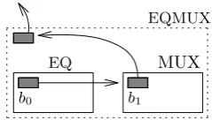
Now we show how to create aSwitch. As an example, we will implement an equality multiplexer (Figure 7). This component, used in our database search component, is called an EQMUX. It takes two pairs: the first pair⟨x, x′⟩is fed into a component for equality testing and the second pair ⟨y, y′⟩is fed into a multiplexer. If x = x′, then the EQMUX outputs y, and otherwise it outputs y′. Just like class Circuit, class Switch
has an arraycomponents that holds its components. It also has an array inputComponentsfor specifying the input receiving components. In this case the two arrays are equal, but there are examples like the minimum component (Figure 3) where this is not the case. Because we have already seen how to implement a constructor and anamemethod, we only specify sub components:
void define sub components() { Bus b1 = new Bus(bus);
MUX mux = new MUX(b1, MUXarity);
OffsetBus b0 = new OffsetBus(mux,
mux.CHOICE); EQ eq = new EQ(b0, EQarity);
components = new Component[] {EQ, MUX}; inputComponents = components;
}
The variablesEQarityand MUXarityare data members ofEQMUX. They denote the bit length of inputs to theEQand theMUX, respectively. The output of EQis one bit fired on port 0. Since this output needs to be given to theMUXon the port that defines the choice bit, we use an offset bus. Having defined the location of this port inMUXas CHOICE, the offset bus can refer to it in a modular fashion, without knowing that the port is at the rightmost position.
Now we create theUniSwitchthat contains theEQcircuits in the set intersection component (Figure 4). Recall that, unlike a Switch, a UniSwitch can contain sub components of only one type and there is no array to hold them. Instead, a balanced binary tree (JavaTreeMap) holds sub components sorted by their index. This allows routing in O(log(n)) time, where nis the number of sub components currently residing
EQ
EQMUX
MUX
b0 b1
Figure 7: An equality multiplexer.
experiments we never had inside theUniSwitchmore than one sub component at a time. This reduces the
UniSwitch cost of routing and memory to O(1). Consequently, our database component uses a constant amount of memory, regardless of the database size. The code below implements the method that builds the sub component. As before, we skip the constructor or the name method of the UniSwitch. The method
setInfoprepares the information for pulling wires, and will be described shortly.
EQ construct sub component(
DynamicBus dynamicBus, int index) { EQ eq = new EQ(dynamicBus, arity); eq.info = setInfo(index);
return eq;
}
The variable arity denotes the bit length of strings compared by EQ. Since the UniSwitch already prepared a DynamicBus for us, all that is left is to instantiate theEQ with this bus, set information about pulling wires, and return theEQobject back to the UniSwitch, who will add it to itsTreeMap.
The functionsetInfotakes the index of the sub component from theUniSwitch. It creates information about pulling wires based on this index and stores it in info, which is a data member of Component. Notice thatsetInfois not a member of UniSwitch, but rather it belongs to the class that we are creating by extending UniSwitch. The variable info is of type ExtraInfo. The reason for this name was to accommodate future information that developers may want to add to components. The method setInfo
therefore instantiates a new instance of ExtraInfoand sets its data member pullingPortsto an array of pulling ports. Elements of this array are of typePTableSocketand contain three integers: port number, table row, and table column. Initiating, for example, pullingPorts as an array {new PTableSocket(p,i,j)}
will make the component pull into portpthe value stored in the table at row iand columnj. Recall that components control when their ports pull. In this case, all ports ofEQare pulling (it is a pulling component). Since it will not be notified with a value, it receives only onepulling notificationfrom its enclosing component. Method setInfo must set upCounter(which is another data member of ExtraInfo) to the inDegree of
EQminus 1. This is because pulling occurs if and only if upCounterequals inDegree. Thus, once theEQ
receives its pulling notification, it will incrementupCounterand immediately pull all of its ports.
4.5
Classes
TestModule
and
Monitor
Once a component has been written, it can be tested for correctness with class TestModule. This class creates an instance of StandardInput. It notifies the component with bits from this input and the function
Calculate. This causes the component to calculate and the output to be directed to an object of class
StandardOutput. The test module enumerates over all possible inputs. If the component implements interfaceTestable, then it can be automatically tested for correctness. Notice that, unlike Fairplay, there is no need to run the full secure protocol to test the function for correctness.
31MB
GB 1.5 number of records
in database
total time in minutes
0.31 13.4 26.7
106
104
GB 3
106 2
Figure 8: Running time of secure database search.
that includes values of relevant variables. Events are implemented in two Javaenum classes. Component events, defined in class ComponentEvent, describe 18 events that occur inside components. These include construction, destruction, reception and sending of signals, pulling and pushing, component output, and so on. Protocol events, defined in class ProtocolEvent, describe 13 protocol related events, such as protocol start and finish, lookup tables sent and received, etc.
As mentioned, components have anID, which is a pair of integers(depth,index). When sub components are built, they are assigned depththat is one higher than their enclosing component, and a unique index
within this component. The monitor displays thisIDalongside reports it receives from components. Developers can add events or create new classes of events. Also, they can configure the monitor, e.g., to display only certain events, or only show events below or above a certain depth. Setting MONITOR=falsein classMonitordisables monitoring.
5
Performance
In this section we analyze the performance of VMCrypt. All tests were executed on a Thinkpad X301 laptop with 3 GB RAM and a 1.6 GHz Intel Core2 Duo processor running Ubuntu Linux. The Java Virtual Machine (JVM) was run as is, without special arguments. Parties communicated through the loopback network interface. Encryption was implemented with SHA-1 modeled as a random oracle, and wire label length was 120 bits. Our conclusions are given in Section 6.
We start with the database search function. The input to this function is an array of records⟨xi, pi⟩and
a stringy, wherexi andpi are viewed as columns in a database table. The output is allpi for whichxi=y.
The component for this function is implemented in VMCrypt as class DBSearch. In the original Fairplay paper [19] it was implemented under the nameKeyed Database Search (KDS).
Since Fairplay circuit parameters are passed at compile time, the compiler must be run in each execution. Thus, we compared the performance of our full protocol with that of the Fairplay compiler [19] alone (ignoring the time and memory it takes to actually execute the Fairplay protocol). Since the time and memory complexity of the Fairplay compiler are not reported in the literature, we carried our own test on a table where the length of each ofxi, pi andy is 20 bits. When the table size isN= 20 records, the compiler runs
for 10 seconds. WhenN = 40 the running time is 50 seconds. Obviously, this is not linear. When N = 55 the compiler runs for 3 minutes and then crashes with a JavaOut Of MemoryError. In the case ofN = 40, memory consumption climbs gradually to 23% of the RAM. WhenN = 55, it reaches 26%.
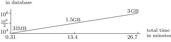
In VMCrypt, whenN = 10,000 the running time of the secure database search protocol is 19 seconds. Figure 8 describes the running time (in minutes) and communication complexity for values of N up to 1 million. The component with 1 million records has 100 million gates and 60 million lookup tables (the number of non-XOR gates).
GB 1.4 28MB
0.3 22.2
104 106
106 2
2.7GB
44.5 set size
total time in minutes
Figure 9: Running time of secure minimum.
3.2GB
0.31 10.3 1581
1000 158
1.3GB
MB
32
25.1
total time in minutes set size
Figure 10: Running time of secure set intersection.
significant savings on disk read and writes. Finally, 84% of the running time was consumed by cryptographic operations and communication. This means that VMCrypt overhead was only 16% (this was measured by calculating the component). Unfortunately, we could not compare this overhead to that of existing garbling algorithms as such statistics are not provided in the literature.
Our next test was the minimum component, implemented in VMCrypt as class MIN (Figure 3). This component takes N integers (of length 20 bits each) and outputs their minimum. In our experiment, half of the integers belong to the client and half belong to the server. We remark that, in practice, parties will have shares of the integers, and the function would first add the shares and then find the minimum.
The running time (in minutes) and communication complexity of the protocol for secure minimum are given in Figure 9. These are linear in N because, as with the DBSearchcomponent, the underlying (non-secure) algorithm runs in linear time. On average, parties used 5% of the memory (independently ofN), and VMCrypt overhead was 10%. Notice that the running time is almost double that of the DBSearch
component. This is because half of the inputs required oblivious transfer, and the number of lookup tables was almost double (theMINcomponent with 1 million inputs had 110 million gates and 90 million lookup tables).
Our last test was the set intersection component, implemented as class SetIntersection (Figure 4). This component takes two sets of size N and M, and outputs their intersection. We fixed the bit length of set elements to 20 bits. To simplify the presentation we choseN =M. The running time (in minutes) and communication complexity of the protocol for secure set intersection are given in Figure 10.
Notice that, unlike previous tests, the size of the set intersection component is quadratic inN due to the underlying (non-secure) algorithm it implements. For comparability with previous tests, we chose values of
N ranging from 158 to 1581. Thus, when N = 158 we haveN2 ∼= 104 and the component has 1 million
gates and 0.5 million lookup tables. Similarly, whenN = 1581 we haveN2 ∼= 106 and the component has 100 million gates and 50 million lookup tables. On average, parties used 5% of the memory (independently ofN), and VMCrypt overhead was 15%.
6
Conclusion
a running time that is linear in the number of gates.
VMCrypt provides a rich toolkit for creating, debugging, and tracking components. These components are Java class files that are compiled once and for all. They can be instantiated and parameterized at run time. This allows secure computation protocols to be run on the fly, without an expensive pre computation phase. Streaming the garbled circuit eliminated storage and disk access costs. As our tests show, these improvements lead to scalability and outstanding performance.
References
[1] M. Barni, T. Bianchi, D. Catalano, M. D. Raimondo, R. D. Labati, and P. Faillia. Privacy-preserving fingercode authentication. InMM&Sec’, Roma, Italy, 2010. ACM.
[2] A. Ben-David, N. Nisan, and B. Pinkas. Fairplaymp: a system for secure multi-party computation. In
ACM Conference on Computer and Communications Security, pages 257–266, 2008.
[3] D. Bogdanov, S. Laur, and J. Willemson. Sharemind: A framework for fast privacy-preserving compu-tations. InESORICS, pages 192–206, 2008.
[4] I. Damg˚ard, M. Geisler, M. Krøigaard, and J. B. Nielsen. Asynchronous multiparty computation: Theory and implementation. InPublic Key Cryptography, pages 160–179, 2009.
[5] I. Damg˚ard and M. Jurik. A generalisation, a simplification and some applications of paillier’s proba-bilistic public-key system. InPublic Key Cryptography, pages 119–136, 2001.
[6] I. Damg˚ard and C. Orlandi. Multiparty computation for dishonest majority: From passive to active security at low cost. InCRYPTO, pages 558–576, 2010.
[7] Z. Erkin, M. Franz, J. Guajardo, S. Katzenbeisser, I. Lagendijk, and T. Toft. Privacy-preserving face recognition. InPrivacy Enhancing Technologies, pages 235–253, 2009.
[8] D. Evans, Y. Huang, J. Katz, and L. Malka. Efficient privacy-preserving biometric identification. To appear in the 17th Proceedings of the Network and Distributed System Security Symposium, NDSS 2011.
[9] M. J. Freedman, K. Nissim, and B. Pinkas. Efficient private matching and set intersection. In EURO-CRYPT, pages 1–19, 2004.
[10] C. Gentry. Fully homomorphic encryption using ideal lattices. InSTOC, pages 169–178, 2009.
[11] W. Henecka, S. Kgl, A.-R. Sadeghi, T. Schneider, and I. Wehrenberg. Tasty: Tool for automating secure two-party computations. InACM Conference on Computer and Communications Security, 2010.
[12] Y. Ishai, J. Kilian, K. Nissim, and E. Petrank. Extending oblivious transfers efficiently. InCRYPTO, pages 145–161, 2003.
[13] S. Jha, L. Kruger, and V. Shmatikov. Towards practical privacy for genomic computation. In IEEE Symposium on Security and Privacy, pages 216–230, 2008.
[14] V. Kolesnikov, A.-R. Sadeghi, and T. Schneider. Improved garbled circuit building blocks and applica-tions to aucapplica-tions and computing minima. InCANS, pages 1–20, 2009.
[15] V. Kolesnikov and T. Schneider. Improved garbled circuit: Free xor gates and applications. InICALP ’08: Proceedings of the 35th international colloquium on Automata, Languages and Programming, Part II, pages 486–498, Berlin, Heidelberg, 2008. Springer-Verlag.
[17] Y. Lindell, B. Pinkas, and N. P. Smart. Implementing two-party computation efficiently with security against malicious adversaries. InSCN, pages 2–20, 2008.
[18] P. D. MacKenzie, A. Oprea, and M. K. Reiter. Automatic generation of two-party computations. In
ACM Conference on Computer and Communications Security, pages 210–219, 2003.
[19] D. Malkhi, N. Nisan, B. Pinkas, and Y. Sella. Fairplay—a secure two-party computation system. In
SSYM’04: Proceedings of the 13th conference on USENIX Security Symposium, pages 20–20, Berkeley, CA, USA, 2004. USENIX Association.
[20] M. Naor and B. Pinkas. Efficient oblivious transfer protocols. InSODA, pages 448–457, 2001.
[21] J. D. Nielsen and M. I. Schwartzbach. A domain-specific programming language for secure multiparty computation. InPLAS, pages 21–30, 2007.
[22] M. Osadchy, B. Pinkas, A. Jarrous, and B. Moskovich. Scifi - a system for secure face identification. In
IEEE Symposium on Security and Privacy, pages 239–254, 2010.
[23] P. Paillier. Public-key cryptosystems based on composite degree residuosity classes. In EURO-CRYPT’99: Proceedings of the 17th international conference on Theory and application of cryptographic techniques, pages 223–238, Berlin, Heidelberg, 1999. Springer-Verlag.
[24] A. Paus, A.-R. Sadeghi, and T. Schneider. Practical secure evaluation of semi-private functions. In
ACNS, pages 89–106, 2009.
[25] B. Pinkas, T. Schneider, N. P. Smart, and S. C. Williams. Secure two-party computation is practical. InASIACRYPT, pages 250–267, 2009.
[26] A.-R. Sadeghi, T. Schneider, and I. Wehrenberg. Efficient privacy-preserving face recognition. InICISC, pages 229–244, 2009.
[27] N. P. Smart and F. Vercauteren. Fully homomorphic encryption with relatively small key and ciphertext sizes. InPublic Key Cryptography, pages 420–443, 2010.
[28] M. van Dijk, C. Gentry, S. Halevi, and V. Vaikuntanathan. Fully homomorphic encryption over the integers. InEUROCRYPT, pages 24–43, 2010.
![Figure 2: Components of the MIN circuit due to [14, 26]](https://thumb-us.123doks.com/thumbv2/123dok_us/1869788.1243267/5.595.115.507.73.185/figure-components-min-circuit.webp)