134
Automated subscriber airtime recharging system using
GSM network and SIM900 wireless module
Ashutosh Behura
1, Loy Larvin Rao
2Faculty of School of Computer Science and Engineering1, School of Computer Science and Engineering2 KIIT University, Bhubaneswar, India1, 2
Email: [email protected]1, [email protected]2
Abstract- Network carrier service centers and kiosks provide prepaid recharge and post-paid bill payment
facilities for their respective carriers. In countries like India, when customers wants to buy airtime, they go to carrier kiosks where salesmen carry out the transaction by sending the subscriber’s number and the amount to be recharged through an SMS to the carrier server. The SMS message is sent through a mobile phone and a register book or spreadsheet is maintained to keep a track of all the transactions done. Since this is done manually, errors in transactions and record maintenance occur frequently. To overcome this, an automated recharge and data logging system was developed which could be plugged in conveniently to any laptop or PC in a kiosk. The system utilizes a SIMCom Sim900 GSM/GPRS module connected to a computer through a RS232 serial port. A driver program on the computer runs a simple graphical interface developed using GTK1.2 to make the process user-friendly. This system will help reduce human error significantly by making the transactions faster, maintaining transaction logs and generating receipts automatically. Also, since the system utilizes GSM network for transaction processing, in the event of internet link failure, it serves as a substitute to web-based recharging applications that require data communication. There by increasing the reliability of transactions.
Index Terms- SIM900, SMS, airtime, subscriber recharge, GSM
1. INTRODUCTION
Mobile network subscribers often have to go to their respective network operator store to buy airtime or pay for their usage of other network services. In countries like India, for years, this process has been carried out by carrier network salesmen who use a mobile phone to send a recharge request to the carrier server. They maintain a register to log the transactions of the day for the purpose of auditing and verifying later. Since this process is done manually, mistakes in obtaining subscriber numbers of customers and errors in log maintenance is common. It takes additional time to generate receipts making the transactions a longer process. Also, in developing cities like Bhubaneswar and other semi-urban areas, where internet link is unreliable, systems that rely on web application to conduct such services come to a disappointing halt very often.
To prevent such mishaps from happening, we built an automated system using a GSM/GPRS module called SIM900 manufactured by SIMCom Wireless Solutions with a serial port interface. This system was built to work with any laptop running on a Ubuntu/Linux platform. A driver algorithm was developed that could communicate with the carrier server by sending and receiving transaction messages through SMS automatically. By applying simple string processing on the server response messages, further action was determined. The driver algorithm was then attached to a GTK interface for user friendly interaction for the salesmen. Since the system used
GSM communication to carry out the transaction, the system also serves as an alternative to web applications in an event of internet link failure. Along with achieving reliability, the main objective was to make the transactions a faster process and maintaining transaction information in the form of log report, hence reducing crowd at recharge counters and serving customers faster.
2. MATERIAL AND METHOD
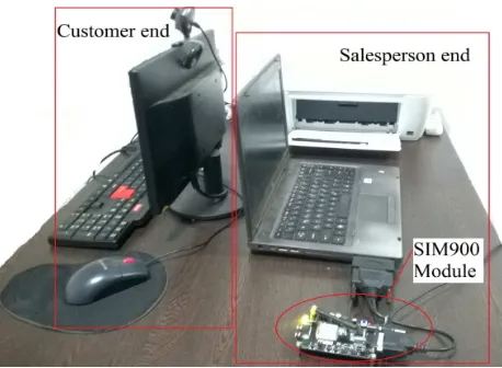
[image:1.595.302.531.571.739.2]To make a system user-friendly for both, the customer and the salesperson to operate, the design of the system included two screens located on either side
135 of the transaction counter displaying the system
interface. With keyboards on both sides, the system allowed the customer to enter his/her name, phone number, recharge type and recharge amount. As shown in Fig. 1, this setup aids in reducing communication gaps since the system engages the customer to enter his/her details. The salesperson only authenticates the transaction by entering the security pin in an entry field whose contents are not visible, just like any other password field. Thus, the chances of wrong information being entered into the system is significantly reduced. Also, in a case when such a mishap happens, the salesperson is no longer responsible for it.
2.1. GSM/GPRS modem
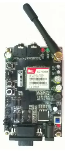
For the purpose of establishing a connection with the carrier server, a GSM/GPRS wireless module was used. SIMCom SIM900 GSM/GPRS module (Fig. 2) is a compact and reliable wireless module manufactured by SIMCom Wireless Solutions. It is a complete Quad-band GSM/GPRS module designed with a single-chip processor integrating AMR926EJ-S core, allowing the user to benefit from small dimensions and cost-effective solutions. Featuring an industry-standard interface, the SIM900 delivers GSM/GPRS 850/900/1800/1900MHz performance for voice, SMS and data, in a small form factor and with low power consumption. With a tiny configuration of 24mm x 24mm x 3 mm, SIM900 can fit almost all the space requirements in all applications, especially for slim and compact demands of design. These modules are usually built into boards that can be connected directly to the computer/laptop through a USB or a serial port. The modem uses Hayes AT commands, for interacting with processor or controller, which are communicated through serial communication. The module that we used to build the system had a RS232 serial port interface to connect with a laptop computer running Ubuntu 12.04.
2.2.Driver program
[image:2.595.119.233.267.532.2]The driver program is a device driver which is written in C and a simple graphical interface is provided using GTK 1.2. GTK 1.2. is preferred because of its portability to other platforms such as Windows. The driver software is designed in a way such that it is user-friendly for the salesperson and the customer as well. The graphical interface as shown in the screenshot in Fig. 3, consists of entry fields necessary to carry out a transaction, such as, the name of the customer, cell phone number, the type of recharge, recharge amount and security pin. Once the data has been entered in the fields and the submit button has been clicked, the driver program collects the data from the interface and starts the process of Fig. 2. SimCOM SIM900 module with serial
interface.
[image:2.595.126.483.590.746.2]136 request generation. It communicates with the module,
and handles the server responses received by the module. After every transaction, the record is maintained in a simple text log file and after every successful transaction, the print button is activated which allows the user to print a receipt of the current transaction. On clicking this button, the driver program generates a receipt by printing the details of the transaction using the default printer and the standard “lpr” command in Linux. The algorithm followed by the driver is described in detail in section 4.
2.3. Port configurations
In order to communicate with the modem through a RS232 serial port, the data needs to be sent in raw mode with specific settings. These appropriate settings were achieved by modifying the termios structure of the terminal device (SIM900 module). The termios data structure is a POSIX compliant data
structure that contains members that configure the terminal input, terminal output, hardware control and local control flags. Fig. 4 shows the termios settings required for proper data transmission and reception by the modem.
3. Recharge request generation and SMS processing
Before carrying out transactions, the driver program must ensure that certain parameters of the SIM900 module are correctly set. This is necessary to properly communicates with the carrier server through SMS messages. To set the correct parameters and to create, send and read SMS messages, the following Hayes AT commands are used:
• ATE<value>\r
This setting determines whether or not the modem echos characters received form the driver program. In this case the value is set to 0, which disables echo. This is important to
properly process the data received from the modem.
• AT+CMGF=<option>\r
This command sets the parameter to denote which input/output format of messages is to be used. In this case we use the option “1” to set text mode for the messages.
• AT+CMGS=”<receiver’s number>”\r This command is used to create an SMS message to be sent to the number mentioned inside the double quotes. After sending this command, the module responds with a prompt “>” requesting the contents of the message. Once the content of the message is sent to the module, the ASCII character 19 which corresponds to Ctrl+Z is sent to the module to signify the end of the content and dispatch the message. If the message is successfully sent, the modem returns
“+CMGS:<message reference number>”.
• AT+CMGR=<index number>\r
This command is used to read the messages stored in the index location mentioned in the argument. The modem responds by transmitting the contents stored in that memory index of the SIM card. This command is useful when it comes to reading the messages sent by the carrier server.
• AT+CMGDA=<option>\r
This command provides the option to clear or delete message from the SIM memory. The driver algorithm requires the “DEL ALL” option to delete all messages when the program starts for the first time or when the SIM memory becomes full.
137 of INR 100 for a cell phone number 999999999 which
is a subscriber of Reliance Telecom, the program generates a string “er100to9999999999” which is recognized by the Reliance server as “Easy Recharge of amount INR 100 to 9999999999” This string is then sent to “53738”, a short code/short number for Reliance Telecom, through a SMS message. Once the message has been sent, the validation system is initiated by the carrier server. The request generation process is explained in a step by step process below:
1) Driver program generates the request message:
AT+CMGS=”2323”\r Er100to9999999999\r ^Z
2) The server receives the message, validates the request and sends a verification code followed by a PIN request if validation is successful. In case it fails, the server sends a message containing the reason for failure. 3) On successful validation by the server, the
driver program receives the message containing the verification code and PIN request. The driver program copies the entire contents of the message received, appends the PIN and sends another message to the carrier server.
4) Depending on the correctness of the PIN the carrier server sends a success or failure message which is logged by the driver program.
Throughout the 4 steps there are several server responses and situations that the driver program needs to handle, such as:
• Incorrect subscriber number that does not exist in server database.
• Insufficient balance to carry out the recharge.
• Incorrect PIN entered during validation process.
• Incorrect recharge amount entered.
• Modem disconnected while transaction in process
4. Driver Algorithm
The following algorithm was developed to carry out the recharge request generation and response handling.
1. START the GTK graphical interface 2. IF the modem is connected:
2.1.Set the tty device settings to raw mode 2.2.IF resume flag = true:
2.2.1. Set resume flag = false 2.2.2. GOTO step 14
2.3.Delete all messages in the SIM card
ELSE:
2.1. Display “modem not connected” 3. Delete all messages in the SIM card 4. Wait for Submit or Close button invocation 5. IF Close button invoked:
5.1.GOTO step 20 6. IF Submit button invoked:
6.1.Locally validate the entered data and ensure the following:
6.1.1. Name field not empty 6.1.2. Recharge type and amount
entered
6.1.3. PIN field not empty 7. If local validation succeeds:
7.1.GOTO step 8
ELSE:
7.1. Display “Invalid field entry” and GOTO step 4
8. Create recharge request string and send a SMS message to carrier server
9. Wait for a server response SMS message (Time out = 2 mins)
10. IF modem connection check returns FALSE or Time out = TRUE:
10.1.Display “Failed/Modem disconnected”
10.2.GOTO step 2
11. IF server response message content = “not a valid number”:
11.1.Display “not a valid number” 11.2.GOTO step 3
12. IF server response message content = “request already placed”:
12.1.Display “request already placed” 12.2.GOTO step 3
13. IF server response message content = “VERIFY=<code>PIN=?”:
13.1. Copy the message contents and append the PIN from the PIN field into a string
13.2. Send the string through a SMS message to the server short number
13.2.1. IF message sent successfully: 13.2.1.1. GOTO step 14
ELSE:
13.2.1.1. Display “Failed/Modem disconnected”
13.2.1.2. GOTO step 2 14. Wait for a server response SMS message 15. IF modem connection check returns FALSE:
15.1.Set resume flag = TRUE 15.2.GOTO step 2
138 16.1.Display “request failed”
16.2.LOG the message into the log file along with subscriber details 16.3.GOTO step 3
17. IF server response message content = “incorrect PIN”:
17.1.Display “Incorrect PIN”
17.2.LOG the message into the log file along with subscriber details 17.3.GOTO step 3
18. IF server response message content = “Successful”:
18.1.Display “Request successful” 18.2.LOG the message into the log file
along with subscriber details 18.3.Prepare receipt and enable Print
button
19. Wait for print or reset button invocation. 20. IF print button invoked:
20.1.Print receipt 20.2.Disable print button 20.3.Reset all fields 21. IF reset button invoked:
21.1.Reset all fields 21.2.Disable print button 22. GOTO step 3
23. END
5. Testing and Comparison
[image:5.595.298.531.107.172.2]For the purpose of testing, the system was installed and tested at Grace Communications, which is a Reliance Telecom service center in Bhubaneswar. To see if the automated system had an advantage over the conventional recharge routine, the system was tested for 4 hours every day over a period of two days and individual transaction times were measured. Customers were alternately directed to the either the automated recharge system or a salesman using the conventional approach. The average time per transaction of the automated system was compared with the conventional method where the salesman used a cellphone to carry out the transaction and created logs and receipts manually. The transaction time mentioned in table 1 and table 2 is the time elapsed from the moment a customer finishes giving his details such as his/her name, type of recharge and amount, up until the moment the system displays a success message on screen. Only successful transactions were taken into consideration for comparison as invalid/failed transactions complete in shorter time and vary widely among test cases.
Table 1. Performance of the automated recharging system
Day Average Transaction
Amount
Average Time per Transaction
Total Transaction
Amount
Day 1 534.15 54.11 13,880 Day 2 455.50 52.25 12,400
Table 2. Performance of conventional method
Day Average Transaction
amount
Average Time per transaction
Total transaction
amount
Day 1 575.35 67.78 14,995 Day 2 442.20 64.02 13,120
Comparing the data from the above tables it is clear that the automated system is on an average 11.77 seconds to 13.67 seconds faster in completing a transaction. Over a vast number transactions these seconds add up to several minutes and save a big chunk of the salesperson time, hence, increasing the rate of customers served every hour, especially during rush hours.
3. CONCLUSION
The efficiency of automated recharge system proves that there can be a market for such devices especially in unban service centers that have to deal with more customers than they can handle. The SIM900 module can be plugged to any PC or laptop computer, though a serial port or using off the shelf serial to USB converters. This makes the system portable, allowing it to be deployed in remote areas. Since the system uses GSM network and SMS messages to carry out the transaction, the system can be used in places where data connectivity is unreliable. The prototype was very cheap to build, making it a cost-effective solution for service centers. In the future the system can be further developed by stacking multiple SIM900 modules, each catering customers subscribed to different network providers Also, an interface that can support multiple modules at once can be developed. This will relieve the hassle and confusion in service centers that provide payment services for more than one network providers.
Acknowledgments
[image:5.595.299.532.203.265.2]139
REFERENCES
[1] Gusev, R.B., Tsymbalenko, V.L. (2010): “A
communication interface of instrumentation modules and a SIM900 crate” Instruments and Experimental
Technique Volume 53, Issue 1, Pages 84-85
[2] Yin, G., Jia, Z.-H., Wang, L.-J. (2011): “Study and design of wireless data communication experiment teaching system based on GPRS” Advances in
Intelligent and Soft Computing Volume 108, Pages
527-534
[3] Sarajlic, A., Omerasevic, D. (2012): “Mobile Account
TopUp over m-commerce platform in IMS
environment” 9th International Symposium on
Telecommunications Conference paper
[4] Wolfgang Gerstacker, Robert Schober, Raimund
Meyer, Frank Obernosterer, Michael Ruder, Hans
Kalveram (2011): “GSM/EDGE: A mobile
communications system determined to stay”
International Journal of Electronics and Communications Volume 65, Issue 8, Pages 694-700
[5] Nithin S., N. Radhika, V. Vanitha (2012): “Smart grid test based on GSM” Procedia Engineering Volume 30, Pages 258-265
[6] GSM-shield-datasheet-Arduino-tutorial, SIM900_AT Command Manual_V1.03, SIM900_EVB kit User
Guide_V1.03.