Volume 2007, Article ID 49389,18pages doi:10.1155/2007/49389
Research Article
Channel Equalization in Filter Bank Based Multicarrier
Modulation for Wireless Communications
Tero Ihalainen,1Tobias Hidalgo Stitz,1Mika Rinne,2and Markku Renfors1
1Institute of Communications Engineering, Tampere University of Technology, P.O. Box 553, Tampere FI-33101, Finland 2Nokia Research Center, P.O. Box 407, Helsinki FI-00045, Finland
Received 5 January 2006; Revised 6 August 2006; Accepted 13 August 2006
Recommended by See-May Phoong
Channel equalization in filter bank based multicarrier (FBMC) modulation is addressed. We utilize an efficient oversampled filter bank concept with 2x-oversampled subcarrier signals that can be equalized independently of each other. Due to Nyquist pulse shaping, consecutive symbol waveforms overlap in time, which calls for special means for equalization. Two alternative linear low-complexity subcarrier equalizer structures are developed together with straightforward channel estimation-based methods to calculate the equalizer coefficients using pointwise equalization within each subband (in a frequency-sampled manner). A novel structure, consisting of a linear-phase FIR amplitude equalizer and an allpass filter as phase equalizer, is found to provide enhanced robustness to timing estimation errors. This allows the receiver to be operated without time synchronization before the filter bank. The coded error-rate performance of FBMC with the studied equalization scheme is compared to a cyclic prefix OFDM reference in wireless mobile channel conditions, taking into account issues like spectral regrowth with practical nonlinear transmitters and sensitivity to frequency offsets. It is further emphasized that FBMC provides flexible means for high-quality frequency selective filtering in the receiver to suppress strong interfering spectral components within or close to the used frequency band.
Copyright © 2007 Tero Ihalainen et al. This is an open access article distributed under the Creative Commons Attribution License, which permits unrestricted use, distribution, and reproduction in any medium, provided the original work is properly cited.
1. INTRODUCTION
Orthogonal frequency division multiplexing (OFDM) [1] has become a widely accepted technique for the realization of broadband air-interfaces in high data rate wireless ac-cess systems. Indeed, due to its inherent robustness to multi-path propagation, OFDM has become the modulation choice for both wireless local area network (WLAN) and terrestrial digital broadcasting (digital audio and video broadcasting; DAB, DVB) standards. Furthermore, multicarrier transmis-sion schemes are generally considered candidates for the fu-ture “beyond 3 G” mobile communications.
All these current multicarrier systems are based on the conventional cyclic prefix OFDM modulation scheme. In such systems, very simple equalization (one complex coef-ficient per subcarrier) is made possible by converting the broadband frequency selective channel into a set of paral-lel flat-fading subchannels. This is achieved using the inverse fast Fourier transform (IFFT) processing and by inserting a time domain guard interval, in the form of a cyclic prefix (CP), to the OFDM symbols at the transmitter. By dimen-sioning the CP longer than the maximum delay spread of the
radio channel, interference from the previous OFDM sym-bol, referred to as inter-symbol-interference (ISI), will only affect the guard interval. At the receiver, the guard interval is discarded to elegantly avoid ISI prior to transforming the signal back to frequency domain using the fast Fourier trans-form (FFT).
later developments is the theory of efficiently implementable, modulation-based uniform filter banks, developed by Vet-terli [17], Malvar [18], Vaidyanathan [19], and Karp and Fliege [20], among others. In this context, the filter banks are used in a transmultiplexer (TMUX) configuration.
We refer to the general concept as filter bank based multi-carrier (FBMC) modulation. In FBMC, the submulti-carrier signals cannot be assumed flat-fading unless the number of subcar-riers is very high. One approach to deal with the fading fre-quency selective channel is to use waveforms that are well lo-calized, that is, the pulse energy both in time and frequency domains is well contained to limit the effect on consecutive symbols and neighboring subchannels [5,7,12]. In this con-text, a basic subcarrier equalizer structure of a single complex coefficient per subcarrier is usually considered. Another ap-proach uses finite impulse response (FIR) filters as subcarrier equalizers with cross-connections between the adjacent sub-channels to cancel the inter-carrier-interference (ICI) [6,10]. A third line of studies applies a receiver filter bank structure providing oversampled subcarrier signals and performs per-subcarrier equalization using FIR filters [4,8,9,11,13]. The main idea here is that equalization of the oversampled sub-carrier signals restores the orthogonality of the subsub-carrier waveforms and there is no need for cross-connections be-tween the subcarriers. This paper contributes to this line of studies by developing low-complexity linear per-subcarrier channel equalizer structures for FBMC. The earlier contri-butions either lack connection to the theory of efficient mul-tirate filter banks, use just a complex multiplier as subcarrier equalizer or, in case of non trivial subcarrier equalizers, lack the analysis of needed equalizer length in practical wireless communication applications (many of such studies have fo-cused purely on wireline transmission). Also various practi-cal issues like peak-to-average power ratio and effects of tim-ing and frequency offsets have not properly been addressed in this context before.
The basic model of the studied adaptive sine modu-lated/cosine modulated filter bank equalizer for transmul-tiplexers (ASCET) has been presented in our earlier work [21–23]. This paper extends the low-complexity equalizer of [23,24], presenting comprehensive performance analysis, and studies the tradeoffs between equalizer complexity and number of subcarriers required to achieve close-to-ideal per-formance in a practical broadband wireless communication environment. A simple channel estimation-based calculation of the equalizer coefficients is presented. The performance of the studied equalizer structures is compared to OFDM, tak-ing into account various practical issues.
In a companion paper [25], a similar subband equalizer structure is applied to the filter bank approach for frequency domain equalization in single carrier transmission. In that context, filter banks are used in the analysis-synthesis config-uration to replace the traditional FFT-IFFT transform-pair in the receiver.
The rest of the paper is organized as follows.Section 2 briefly describes an efficient implementation structure for the TMUX based on exponentially modulated filter banks (EMFB) [26]. The structure consists of a critically sampled
synthesis and a 2x-oversampled analysis bank. The problem of channel equalization is addressed inSection 3. The theo-retical background and principles of the proposed compen-sation method are presented. The chosen filter bank struc-ture leads to a relatively simple signal model that results in criteria for perfect subcarrier equalization and formulas for FBMC performance analysis in case of practical equalizers. A complex FIR filter-based subcarrier equalizer (CFIR-SCE) and the so-called amplitude-phase (AP-SCE) equalizer are presented. Especially, some low-complexity cases are ana-lyzed and compared in Section 4. In Section 5, we present a semianalytical and a full time domain simulation setup to evaluate the performance of the equalizer structures in a broadband wireless communication channel. Furthermore, the effects of timing and frequency offsets, nonlinearity of a power amplifier, and overall system complexity are briefly investigated. Finally, the conclusions are drawn inSection 6.
2. EXPONENTIALLY MODULATED PERFECT RECONSTRUCTION TRANSMULTIPLEXER
Figure 1 shows the structure of the complex exponen-tially modulated TMUX that can produce a complex in-phase/quadrature (I/Q) baseband signal required for spec-trally efficient radio communications [23]. It has real format for the low-rate input signals and complex I/Q-presentation for the high-rate channel signal. It should be noted that FBMC with (real) m-PAM as subcarrier modulation and OFDM with (complex)m2-QAM ideally provide the same bit rate since in general the subcarrier symbol rate in FBMC is twice that of OFDM for a fixed subchannel spacing. In this structure, there are 2Mlow-rate subchannels equally spaced between [−Fs/2,Fs/2],Fsdenoting the high sampling rate.
EMFBs belong to a class of filter banks in which the subfilters are formed by frequency shifting the lowpass pro-totypehp[n] with an exponential sequence [27].
Exponen-tial modulation translates Hp(ejω) (lowpass frequency
re-sponse) around the new center frequency determined by the subcarrier index k. The prototypehp[n] can be optimized
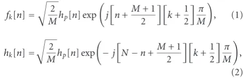
in such a manner that the filter bank satisfies the perfect-reconstruction (PR) condition, that is, the output signal is a delayed version of the input signal [27, 28]. In the gen-eral form, the synthesis and analysis filters of EMFBs can be written as
fk[n]=
2
Mhp[n] exp
j
n+M+ 1
2
k+1
2
π M
, (1)
hk[n]=
2
Mhp[n] exp
−j
N−n+M+ 1
2
k+1
2
π M
,
(2)
respectively, wheren=0, 1,. . .,Nandk=0, 1,. . ., 2M−1. Furthermore, it is assumed that the filter order isN=2KM−
CMFB synthesis
SMFB synthesis xk[m]
x2M 1 k[m] FM(ω)
π
0 π
F2M1(ω)F0(ω)F1(ω) FM1(ω)
Channel
Re
Im
CMFB analysis SMFB analysis
CMFB analysis SMFB analysis +
1/2
+ 1/2
j +
+
+ +
+ I Q I
Q SCE
SCE
Re
Re
xk[m]
x2M 1 k[m]
Figure1: Complex TMUX with oversampled analysis bank and per-subcarrier equalizers.
the roll-offparameterρdetermines how much adjacent sub-channels overlap. Typically, ρ = 1.0 is used, in which case only the contiguous subchannels are overlapping with each other, and the overall subchannel bandwidth is twice the sub-channel spacing.
In the approach selected here, the EMFB is implemented using cosine and sine modulated filter bank (CMFB/SMFB) blocks [28], as can be seen inFigure 1. The extended lapped transform (ELT) is an efficient method for implementing PR CMFBs [18] and SMFBs [28]. The relations between the syn-thesis and analysis filters of the 2M-channel EMFB and the correspondingM-channel CMFB and SMFB with the same real FIR prototypehp[n] are
fk[n]=
⎧ ⎨ ⎩
fkc[n] +j fks[n], k∈[0,M−1]
−f2cM−1−k[n]−j f2sM−1−k[n]
, k∈[M, 2M−1], (3)
hk[n]=
⎧ ⎨ ⎩ hc
k[n]−jhsk[n], k∈[0,M−1]
−hc
2M−1−k[n]+jhs2M−1−k[n]
, k∈[M, 2M−1], (4)
respectively. A specific feature of the structure inFigure 1is that while the synthesis filter bank is critically sampled, the subchannel output signals of the analysis bank are oversam-pled [26] by a factor of two. This is achieved by using the symbol-rate complex (I/Q) subchannel signals, instead of the real ones that are sufficient for detection after the channel equalizer, or in case of a distortion-free channel.
We consider here the use of EMFBs which have odd chan-nel stacking, that is, the center-most pair of subchanchan-nels is symmetrically located around the zero frequency at the base-band. We could equally well use a modified EMFB struc-ture [26] with even stacking (the center-most subchannel lo-cated symmetrically about zero). The latter form has also a slightly more efficient implementation structure, based on DFT-processing. The proposed equalizer structure can also be applied with modified DFT (MDFT) filter banks [20], with modified subchannel processing. However, for the fol-lowing analysis EMFB was selected since it results in the most straightforward system model.
Further, although the discussion here is based on the use of PR filter banks, also nearly perfect-reconstruction (NPR) designs could be utilized. In the critically sampled case, the implementation benefits of NPR designs are limited because the efficient ELT structures cannot be utilized [29]. However, in the 2x-oversampled case, having two parallel CMFB and SMFB blocks, the implementation benefits of NPR designs could be more significant.
3. CHANNEL EQUALIZATION
The problem of channel equalization in the FBMC context is not so well understood as in the DFT-based systems. Our equalizer concept can be applied to both real and complex modulated baseband signal formats; here we focus on the complex case. In its simplest form, the subcarrier equalizer structure consists only of a single complex coefficient that adjusts the amplitude and phase responses of each subchan-nel in the receiver [22]. Higher-order SCEs are able to equal-ize each subchannel better if the channel frequency response is not flat within the subchannel. As a result, the use of higher-order SCEs enables to increase the relative subchan-nel bandwidth because the subchansubchan-nel responses are allowed to take mildly frequency selective shapes. As a consequence, the number of subchannels to cover a given signal band-width by FBMC can be reduced. In general, higher-order equalizer structures provide flexibility and scalability to sys-tem design because they offer a tradeoffbetween the num-ber of required subchannels and complexity of the subcarrier equalizers.
3.1. Theoretical background and principles
Figure 2(a) shows a subchannel model of the complex TMUX with per-subcarrier equalizer. A more detailed model that includes the interference from the contiguous subchan-nels is shown inFigure 2(b). Limiting the sources of inter-ference to the closest neighboring subchannels is justified if the filter bank design provides sufficiently high stopband at-tenuation. Furthermore, in this model the order of down-sampling and equalization is interchanged based on the mul-tirate identities [19]. The latter model is used as a basis for the cross-talk analysis that follows. It is also convenient for semianalytical performance evaluations. The equalizer con-cept is based on the property that with ideal sampling and equalization, the desired subchannel signal, carried by the real part of the complex subchannel output, is orthogonal to the contiguous subchannel signal components occupying the imaginary part. The orthogonality between the subchan-nels is introduced when the linear-phase lowpass prototype
hp[n] is exponentially frequency shifted as a bandpass filter,
with 90-degree phase-shift between the carriers of the con-tiguous subchannels.
In practice, the nonideal channel causes amplitude and phase distortion. The latter results in rotation between the I-and Q-components of the neighboring subchannel signals causing ICI or cross-talk between the subchannels. ISI, on the other hand, is mainly caused by the amplitude distortion. The following set of equations provides proofs for these state-ments. We derive them for an arbitrary subchannelkon the positive side of the baseband spectrum and the results can easily be extended for the subchannels on the negative side using (3) and (4). In the following analysis we use a non-causal zero-phase system model, which is obtained by using, instead of (2), analysis filters of the form
hk[n]=
2
Mhp[n+N] exp
−j
−n+M+1
2
k+1
2
π M
.
(5)
By referring to the equivalent form, shown inFigure 2(b), and adopting the notation from there, we can express the cas-cade of the synthesis and analysis filters of the desired sub-channelkas
fk[n]∗hk[n]= b
l=a
hck[l]fkc[n−l] + b
l=a
hsk[l]fks[n−l]
+j· b
l=a
hck[l]fks[n−l]− b
l=a
hsk[l]fkc[n−l]
=tI
k[n] +j·t Q
k[n]=tk[n],
(6)
where∗denotes the convolution operation, summation in-dexes are a = −N + max(n, 0) and b = min(n, 0), and
n∈[−N,. . .,N].
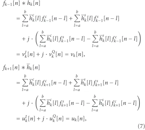
3.1.1. ICI analysis
For the potential ICI terms from the contiguous subchannels
k−1 andk+ 1 (below and above) to the subchannelkof interest, we can write
fk−1[n]∗hk[n]
=
b
l=a
hck[l]fkc−1[n−l] +
b
l=a
hsk[l]fks−1[n−l]
+j· b
l=a
hck[l]fks−1[n−l]−
b
l=a
hsk[l]fkc−1[n−l]
=vI
k[n] +j·v Q
k[n]=vk[n],
fk+1[n]∗hk[n]
=
b
l=a
hck[l]fkc+1[n−l] +
b
l=a
hsk[l]fks+1[n−l]
+j· b
l=a
hck[l]fks+1[n−l]−
b
l=a
hsk[l]fkc+1[n−l]
=uIk[n] +j·u Q
k[n]=uk[n],
(7)
respectively.
Due to PR design, the real partsvI
k[m] anduIk[m] (m
be-ing the sample index at the low rate) of the downsampled subchannel signals are all-zero sequences (or close to zero sequences in the NPR case). So ideally, when the real part of the signal is taken in the receiver, no crosstalk from the neighboring subchannels is present in the signal used for de-tection. Channel distortion, however, causes phase rotation between the I- and Q-components breaking the orthogonal-ity between the subcarriers. Channel equalization is required to recover the orthogonality of the subcarriers.
The ICI components from other subcarriers located fur-ther apart from the subchannel of interest are considered negligible. This is a reasonable assumption because the ex-tent of overlapping of subchannel spectra and the level of stopband attenuation can easily be controlled in FBMC. In fact, they are used as optimization criteria in filter bank de-sign, as discussed in the previous section.
The cascade of the distorting channel with instantaneous impulse response (in the baseband model) hch[n] and the upsampled version of the per-subcarrier equalizerck[n] (see
Figure 2) applied to the subchannel k of interest can be expressed as
hch[n]∗ck[n]=rk[n]. (8)
In the analysis, a noncausal high-rate impulse responseck[n]
is used for the equalizer, although in practice the low-rate causal formck[m] is applied.
Distorting channel M fk[n]
Xk
hch[n] hk[n] M ck[m] Re
Xk
Synthesis bank Analysis bank Equalizer
(a)
M
M
M uI
k[n] +ju
Q
k[n]
=fk+1[n] hk[n] tI
k[n] +jtQk[n]
=fk[n] hk[n] vI
k[n] +jv
Q
k[n]
=fk 1[n] hk[n] Xk+1
Xk
Xk 1
+ r
I
k[n] +jr
Q
k[n]
=hch[n] ck[n]
Re M
Xk
ck[n]= ⎧ ⎨ ⎩ck
[n/m], forn=mM,mZ
0, otherwise (b)
Figure2: Complex TMUX with per-subcarrier equalizer. (a) System model for subchannelk. (b) Equivalent form including also contiguous subchannels for crosstalk analysis.
Desired subchannel
π 2M
3π 2M
0 ω
RX filter of the desired subchannel TX filter of the contiguous subchannel Potential ICI spectrum
Figure3: Potential ICI spectrum for subchannelk=0.
is symmetrically located about zero frequency. We can write the baseband cross-talk impulse response from subchannel
k−1 to subchannelkin case of an ideal channel as
vk[n]=vIk[n] +jv Q
k[n]=vk[n]e−jnkπ/M. (9)
In the appendix, it is shown that this impulse response is purely imaginary, that is,vI
k[n] ≡ 0 andvk[n] = v0[n]. In case of nonideal channel with channel equalization, the base-band cross-talk impulse response can now be written as
gk−1
k [n]= jv Q
0[n]∗rk[n], (10)
whererk[n]= rk[n]e−jnkπ/M. Here the upper index denotes
the source of ICI. Now we can see that if the equalized chan-nel impulse response is real in the baseband model, then the cross-talk impulse response is purely imaginary, and there is no lower-side ICI in the real part of the subchannel signal that is used for detection.
At this point we have to notice that the lower-side ICI energy is zero-centered after decimation only for the even-indexed subchannels, and for the odd subchannels the above
model is not valid as such. However, we can establish a sim-ple relation between the actual decimated subchannel output sequencezk[mM] in the filter bank system and the sequence
obtained by decimating in the baseband model. It is straight-forward to see that the following relation holds:
zk[n]e−jnkπ/M
n=mM=(−1) mkz
k[mM]. (11)
Thus, for odd subchannels, the actual decimated ICI se-quence is obtained by lowpass-to-highpass transformation (i.e., through multiplication by an alternating±1-sequence) from the ICI sequence of the baseband model. Then the ac-tual ICI is guaranteed to be zero if it is zero in the baseband model. Therefore, a sufficient condition for zero lower-side ICI in all subchannels is that the equalized baseband channel impulse response is purely real.
For the upper-side ICI, we can first write the baseband model as
uk[n]=uIk[n] +ju Q
k[n]=uk[n]e−jn(k+1)π/M. (12)
Again, it is shown in the appendix that this baseband im-pulse response is purely imaginary, that is, uIk[n] ≡ 0 and
uk[n] = u2M−1[n]. With equalized nonideal channel, the cross-talk response is now
gk+1
k [n]=ju Q
2M−1[n]∗
rk[n]e−jnπ/M
(13)
and the upper-side ICI vanishes if the equalized channel im-pulse response is real in this baseband model. Now the rela-tion between the decimated models is
zk[n]e−jn(k+1)π/M
n=mM=(−1) m(k+1)z
and a sufficient condition also for zero upper-side ICI is that the equalized baseband channel impulse response is purely real. However, the baseband models for the two cases are slightly different, and both conditions
Imrk[n]
≡0,
Imrk[n]e−jnπ/M
≡0
(15)
have to be simultaneously satisfied to achieve zero over-all ICI. In frequency domain, the equalized channel fre-quency response is required to have symmetric amplitude and antisymmetric phase with respect to both of the fre-quencieskπ/Mand (k+ 1)π/Mto suppress both ICI com-ponents. Naturally, the ideal full-band channel equaliza-tion (resulting in constant amplitude and zero phase) im-plies both conditions. In our FBMC system, the equal-ization is performed at low rate, after filtering and dec-imation by M, and the mentioned two frequencies cor-respond to 0 and π, that is, the filtered and downsam-pled portion of Hch(ejω) in subchannel k multiplied by the equalizer Ck(ejω) must fulfill the symmetry condition
for zero ICI. In this case, the two symmetry conditions are equivalent (i.e., symmetric amplitude around 0 implies symmetric amplitude around π, and antisymmetric phase around 0 implies antisymmetric phase aroundπ). The tar-get is to approximate ideal channel equalization over the subchannel passband and transition bands with sufficient accuracy.
3.1.2. ISI analysis
In case of an ideal channel, the desired subchannel impulse response of the baseband model can be written as
tk[n]=t
I k[n] +jt
Q
k[n]=tk[n]e−jnkπ/M. (16)
For odd subchannels, a lowpass-to-highpass transformation has to be included in the model to get the actual response for the decimated filter bank, but the model above is suitable for analyzing all subchannels. Now the real part of the subchan-nel response with actual chansubchan-nel and equalizer can be written (see the appendix) as
gk[n]=Re
tk[n]∗rk[n]
=Ret0[n]∗rk[n]
=t0I[n]∗Re
rk[n]
−tQ0[n]∗Im
rk[n]
.
(17)
The conditions for suppressing ICI are also sufficient for sup-pressing the latter term of this equation. Furthermore, in case of PR filter bank design,tI
0[n] is a Nyquist pulse. Designing the channel equalizer to provide unit amplitude and zero-phase response, a condition equivalent of having
Rerk[n]
=δ[n]= ⎧ ⎨ ⎩
1, n=0,
0, otherwise, (18)
would suppress the ISI within the subchannel.
The above conditions were derived in the high-rate, full-band case, and if the conditions are fully satisfied, ISI within the subchannel and ICI from the lower and upper adja-cent subchannels are completely eliminated. In practice, the equalization takes place at the decimated low sampling rate, and can be done only within the passband and transition band regions (assuming roll-offρ =1.0). However, the ICI and ISI components outside the equalization band are pro-portional to the stopband attenuation of the subchannel fil-ters and can be ignored.
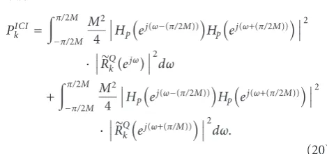
3.2. Optimization criteria for the equalizer coefficients
Our interest is in low-complexity subcarrier equalizers, which do not necessarily provide responses very close to the ideal in all cases. Therefore, it is important to analyze the ICI and ISI effects with practical equalizers. This can be carried out most conveniently in frequency domain. In the baseband model, the lower and upper ICI spectrum magnitudes are
VQ k(ejω)R
Q k(ejω)
=V0Q(ejω)R
Q k(ejω)
=M
2
Hp
ej(ω−(π/2M))H
p
ej(ω+(π/2M))·RQ k(ejω),
UQ k
ejωRQ
k
ej(ω+(π/M))
=U2QM−1
ejω RQ
k
ej(ω+(π/M))
=M
2
Hp
ej(ω−(π/2M))H
p
ej(ω+(π/2M))·RQ k
ej(ω+(π/M)), (19)
respectively. Here the upper-case symbols stand for the Fourier transforms of the impulse responses denoted by the corresponding lower-case symbols. The terms involving the two frequency shifted prototype frequency responses are the overall magnitude response for the crosstalk.Hp(ej(ω−(π/2M)))
appears here as the receive filter for the desired subchan-nel andHp(ej(ω+(π/2M))) denotes the response of the
trans-mit filter of the contiguous (potentially interfering) subchan-nel. The actual frequency response includes phase terms, but based on the discussion in the previous subsection we know that, in the baseband model of the ideal channel case, all the cross-talk energy is in the imaginary part of the impulse response. The residual imaginary part of the equalized channel impulse responserkQ[n] determines how
model
PkICI=
π/2M
−π/2M
M2 4
Hp
ej(ω−(π/2M))H
p
ej(ω+(π/2M))2
·RQk
ejω2dω
+
π/2M
−π/2M
M2 4
Hp
ej(ω−(π/2M))H
p
ej(ω+(π/2M))2
·RQk
ej(ω+(π/M))2dω.
(20)
Also the ISI power can be calculated, as soon as the chan-nel and equalizer responses are known, from the aliased spectrum ofGk(ejω), as
PISI k =
π/M
0
M−
1
l=−1
Gk
ej(ω+(lπ/M))
2
dω. (21)
Here, the Nyquist criterion in frequency domain is used: in ISI-free conditions, the folded spectrum of the overall subchannel responseGk(ejω) adds up to a constant levelM, a
condition equivalent to overall impulse response being unity impulse. By calculating the difference between this ideal ref-erence level and the actual spectrum, the spectrum resulting from the residual ISI can be extracted. Integration over this residual spectrum gives the ISI power, according to (21).
Typically, the pulse shape applied to the symbol detector, the slicer, is constrained to satisfy the Nyquist criterion. In the presence of ISI, this often requires from the receive filter (in this context, the term “receive filter” is assumed to in-clude both the analysis filter and the equalizer) a gain that compensates for the channel loss and causes the noise power to be amplified. This is called noise enhancement. The sub-channel noise gain can be calculated as
βn k=
1 2π
π
−π
Ck
ejωH
p
ej((ω∓π/2)/M)2dω, (22)
whereCk(ejω) is the response of the subchannel equalizer.
The −and + signs are valid for even and odd subchannel indexes, respectively.
3.3. Semianalytical performance evaluation
The performance of the studied FBMC, using per-subcarrier equalization to combat multipath distortion, can be evalu-ated semianalytically according to the discussion above. The term “semianalytically” refers, in this context, to the fact that no actual signal needs to be generated for transmission. In-stead, a frequency domain analysis of the distorting channel and the equalizer can be applied to derive the ICI and ISI power spectra and the noise enhancement involved. Based onPkICI,PkISI, andβkn, the overall signal to interference plus
noise ratio(s) (SINR) for given Eb/N0-value(s) can be ob-tained. Then, well-known formulas based on the Q-function [30] and Gray-coding assumption can be exploited to esti-mate the uncoded bit error-rate (BER) performance. This can further be averaged over a number of channel instances corresponding to a given power delay profile.
4. LOW-COMPLEXITY POINTWISE PER-SUBCARRIER EQUALIZATION
The known channel equalization solutions for FBMC suffer from insufficient performance, as in the case of the 0th-order ASCET [22], and/or from relatively high implementation complexity, as in the FIR filter based approach described, for example, by Hirosaki in [4]. To overcome these problems, a specific structure that equalizes at certain frequency points is considered. The pointwise equalization principle proceeds from the consideration that the subchannel equalizers are designed to equalize the channel optimally at certain fre-quency points within the subband. To be more precise, the coefficients of the equalizer are set such that, at all the con-sidered frequency points, the equalizer amplitude response optimally approaches the inverse of the determined chan-nel amplitude response and the equalizer phase response optimally approaches the negative of the determined chan-nel phase response. Optimal equalization at all frequencies would implicitly fulfill the zero ICI conditions of (15), and the zero ISI condition of (18). In pointwise equalization, the optimal linear equalizer is approximated between the con-sidered points and the residual ICI and ISI interference pow-ers depend on the degree of inaccuracy with respect to the zero ICI/ISI conditions and can be measured using (20) and (21), respectively. On the other hand, the level of inaccu-racy depends on the relation of the channel coherence band-width [31] to the size of the filter bank and the order of the pointwise per-subcarrier equalizer. For mildly frequency selective subband responses, low-complexity structures are sufficient to keep the residual ICI and ISI at tolerable lev-els.
Alternative optimization criteria are possible for the equalizer coefficients from the amplitude equalization point of view, namely, zero-forcing (ZF) and mean-squared error (MSE) criteria [30,31]. The most straightforward approach is ZF, where the coefficients are set such that the achieved equalizer response compensates the channel response ex-actly at the predetermined frequency points. The ZF crite-rion aims to minimize thePICIk andPISIk , but ignores the
ef-fect of noise. Ultimately, the goal is to minimize the proba-bility of decision errors. The MSE criterion tries to achieve this goal by making a tradeoffbetween the noise enhance-ment and residual ISI at the slicer input. The MSE criterion thus alleviates the noise enhancement problem of ZF and could provide improved performance for those subchannels that coincide with the deep notches in the channel frequency response. For high SNR, the MSE solution of the ampli-tude equalizer converges to that obtained by the ZF crite-rion.
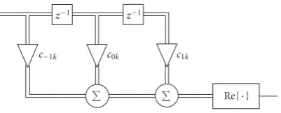
4.1. Complex FIR equalizer
z 1 z 1
c 1k c0k c1k
Re
Figure4: An example structure of the CFIR-SCE subcarrier equal-izer.
frequency points, a 3-tap complex FIR with noncausal trans-fer function
HCFIR - SCE(z)=c−1z+c0+c1z−1 (23)
offers the needed degrees of freedom. The equalizer coef-ficients are calculated by evaluating the transfer function, which is set to the desired response, at the chosen frequency points and setting up an equation system that is solved for the coefficients.
4.2. Amplitude-phase equalizer
We consider a linear equalizer structure consisting of an all-pass phase correction section and a linear-phase amplitude equalizer section. This structure is applied to each complex subchannel signal for separately adjusting the amplitude and phase. This particular structure makes it possible to indepen-dently design the amplitude equalization and phase equaliza-tion parts, leading to simple algorithms for optimizing the equalizer coefficients. The orders of the equalizer stages are chosen to obtain a low-complexity solution. A few variants of the filter structure have been studied and will be described in the following.
An example structure of the AP-SCE equalizer is illus-trated in detail in Figure 5. In this case, each subchannel equalizer comprises a cascade of a first-order complex all-pass filter, a phase rotator combined with the operation of taking the real part of the signal, and a first-order real allpass filter for compensating the phase distortion. The structure, moreover, consists of a symmetric 5-tap FIR filter for com-pensating the amplitude distortion. Note that the operation of taking the real part of the signal for detection is moved before the real allpass phase correction stage. This does not affect the output of the AP-SCE, but reduces its implementa-tion complexity.
The transfer functions of the real and complex first-order allpass filters are given by
Hr(z)=
1 +brz
1 +brz−1
, (24)
Hc(z)=
1−jbcz
1 +jbcz−1, (25)
respectively. In practice, these filters are realized in the causal form as z−1H
·(z), but the above noncausal forms simplify
the following analysis. For the considered example structure,
the overall phase response of the AP-SCE phase correction section (for thekth subchannel) can be derived from (24) and (25)
argHpeq(ejω)
=argejϕ0k·H
c
ejω·H
r
ejω
=ϕ0k+ 2 arctan
−bckcosω
1 +bcksinω
+ 2 arctan
brksinω
1 +brkcosω
.
(26)
In a similar manner, we can express the transfer function of the amplitude equalizer section in a noncausal form as
Haeq(z)=a2z2+a1z+a0+a1z−1+a2z−2, (27)
from which the equalizer magnitude response for the kth subchannel is obtained
Haeq(ejω)=a0k+ 2a1kcosω+ 2a2kcos 2ω. (28)
4.3. Low-complexity AP-SCE and CFIR-SCE
Case 1. The subchannel equalization is based on a single fre-quency point located at the center frefre-quency of a specific subchannel, at ±π/2 at the low sampling rate. Here the + sign is valid for the even and the−sign is valid for the odd subchannel indexes, respectively. In this case, the associated phase equalizer only has to comprise a complex coefficient
ejϕ0kfor phase rotation. The amplitude equalizer is reduced to just one real coefficient as a scaling factor. This case corre-sponds to the 0th-order ASCET or a single-tap CFIR-SCE.
Case 2. Here, equalization at two frequency points located at the edges of the passband of a specific subchannel, atω=0 andω= ±π, is expected to be sufficient. The + and−signs are again valid for the even and odd subchannels, respec-tively. In this case, the associated equalizer has to comprise, in addition to the complex coefficientejϕ0k, the first-order com-plex allpass filter as the phase equalizer, and a symmetric 3-tap FIR filter as the amplitude equalizer. Compared to the equalizer structure ofFigure 5, the real allpass filter is omit-ted and the length of the 5-tap FIR filter is reduced to 3. In the CFIR-SCE approach, two taps are used.
Case 3. Here, three frequency points are used for channel equalization. One frequency point is located at the center of the subchannel frequency band, atω = ±π/2, and two fre-quency points are located at the passband edges of the sub-channel, atω=0 andω = ±π. In this case, the associated equalizer has to comprise all the components of the equalizer structure depicted inFigure 5. In the CFIR-SCE structure of Figure 4, all three taps are used.
bck j
z 1
Complex allpass filter
bck j
z 1 ejϕ0k
Re
brk
z 1
z 1
brk
Real allpass filter
z 1 z 1 z 1 z 1
a2k a1k a0k a1k a2k
5-tap symmetric FIR Phase equalizer
Phase rotator
Amplitude equalizer
Figure5: An example structure of the AP-SCE subcarrier equalizer.
example,Case 3phase equalization could be combined with Case 2amplitude correction and so forth. Ideally, the num-ber of frequency points considered within each subchannel is not fixed in advance, but can be individually determined for each subchannel based on the frequency domain channel es-timates of each data block. This enables the structure of each subchannel equalizer to be controlled such that the associ-ated subchannel response is equalized optimally at the mini-mum number of frequency points which can be expected to result in sufficient performance. The CFIR-SCE cannot pro-vide such mixed cases.
Also further cases could be considered since additional frequency points are expected to result in better performance when the subband channel response is more selective. How-ever, this comes at the cost of increased complexity in pro-cessing the data samples and much more complicated for-mulas for obtaining the equalizer coefficients.
ForCase 3 structure, CFIR-SCE and AP-SCE equalizer coefficients can be calculated by evaluating (23) and (26), and (28), respectively, at the frequency points of interest, set-ting them equal to the target values, and solving the resulset-ting system of equations for the equalizer coefficients:
CFIR-SCE:
c−1k=
γ
4
χ0k−χ2k
∓j2χ1k−χ0k−χ2k
,
c0k=γ
2
χ0k+χ2k
,
c1k=γ
4
χ0k−χ2k
±j(2χ1k−χ0k−χ2k)
;
(29)
AP-SCE:
ϕ0k=ξ0k
+ξ2k
2 ,
bck= ±tan
ξ2k−ξ0k
4
,
brk= ±tan
ξ1k−ϕ0k
2
,
a0k=γ
4
0k+ 21k+2k
,
a1k= ±γ
4
0k−2k
,
a2k=
γ
8
0k−21k+2k
.
(30)
Here the±signs are again for the even/odd subchan-nels, respectively, andχik,ξik, and ik,i = 0,. . ., 2, are the
complex target response, the target phase, and amplitude re-sponse values at the three considered frequency points for subchannelk. The valuei =1 corresponds to the subchan-nel center frequency whereas valuesi=0 andi=2 refer to the lower and upper passband edge frequencies, respectively. With MSE criterion,
χik= Hch
ej(2k+i)(π/2M)∗
Hch
ej(2k+i)(π/2M)2+η ,
ξik=arg
χik
, ik=χik,
(31)
whereHchis the channel frequency response in the baseband model of the overall system. The effect of noise enhance-ment is incorporated into the solution of the equalizer pa-rameters using the noise-to-signal ratioηand a scaling fac-torγ=3/2i=0χikHch(ej(2k+i)(π/2M)) that normalizes the sub-channel signal power to avoid any scaling in the symbol val-ues used for detection. In the case of ZF criterion,η=0 and
γ=1.
The operation of the ZF-optimized amplitude and phase equalizer sections ofCase 3AP-SCE are illustrated with ran-domly selected subchannel responses in Figures6and7, re-spectively.
InCase 2, MSE-optimized coefficients for CFIR-SCE and AP-SCE amplitude equalizer can be calculated as
c0k=
γ
2
χ0k+χ2k
,
c1k= ±γ
2
χ0k−χ2k
,
a0k=
γ
2
0k+2k
,
a1k= ±γ
4
0k−2k
,
(32)
whereγ =2/(χ0kHch(ej(kπ/M)) +χ2kHch(ej(2k+2)(π/2M))). The AP-SCE phase equalizer coefficientsϕ0k andbck can be
ob-tained as inCase 3.
Case 1equalizers are obtained as special cases of the used structures, including only a single complex coefficient for CFIR-SCE and an amplitude scaling factor and a phase ro-tator for AP-SCE. It is natural to calculate these coefficients based on the frequency response values at the subchannel center frequencies, that is,
c0k=χ1k,
a0k=χ1k, ϕ0k=arg
χ1k
, (33)
1 0.9 0.8 0.7 0.6 0.5 0.4 0.3 0.2 0.1 0
Channel response Equalizer target pointsεi
Equalizer amplitude response
Combined response of channel and equalizer Normalized frequency (Fs/2)
0 0.5 1 1.5 2 2.5 3 3.5
A
m
plitude
in
linear
scale
ε0
ε1
ε2
Figure6: Operation of the ZF-optimizedCase 3amplitude equal-izer section.
0 0.1 0.2 0.3 0.4 0.5 0.6 0.7 0.8 0.9 1
Channel response Equalizer target pointsξi
Equalizer phase response
Combined response of channel and equalizer Normalized frequency (Fs/2)
60 40 20 0 20 40 60
Phase
(deg
rees)
ξ0 ξ
1
ξ2
Figure7: Operation of theCase 3phase equalizer section.
5. NUMERICAL RESULTS
The performance of the low-complexity subcarrier equal-izers was evaluated with different number of subchannels both semianalytically and using full simulations in time do-main. First, basic results are reported to illustrate how the performance depends on the number of subcarriers and the equalizer design case. Also the reliability of the semianalytical model is examined and the differences between ZF and MSE criteria are compared. Finally, more complete simulations
with error control coding are reported and compared to an OFDM reference in a realistic simulation environment. Also sensitivity to timing and frequency offsets and performance with practical transmitter power amplifiers are investigated. We consider equally spaced real 2-PAM, 4-PAM, and 8-PAM constellations for FBMC and complex square-constellations QPSK, 16-QAM, and 64-QAM in the OFDM case.
5.1. Semianalytical performance evaluation
Semianalytical simulations were carried out with the Vehicular-A power delay profile (PDP), defined by the rec-ommendations of the ITU [32], for a 20 MHz signal band-width. These simulations were performed in quasi-static conditions, that is, the channel was time-invariant during each transmitted frame. Perfect channel information was as-sumed. In all the simulations, the average channel power gain was scaled to unity. Performance was tested with filter banks consisting of 2M = {64, 128, 256}subchannels. The filter bank designs used roll-offρ = 1.0 and overlapping factor
K = 5 resulting in about 50 dB stopband attenuation. The statistics are based on 2000 frame transmissions for each of which an independent channel realization was considered. The semianalytical results were obtained by calculating the subcarrierwise ICI and ISI powersPICI
k andPkISI, respectively,
together with noise gainsβn
k fork=0, 1,. . ., 2M−1. These
were then used to determine the subcarrierwise SINR-values, as a function of channelEb/N0-values, for all the channel in-stances. The uncoded BER results were obtained for 2-, 4-, and 8-PAM modulations by evaluating first the theoretical subcarrierwise BERs based on the SINR-values using the Q-function and Gray-coding assumption, and finally averaging the BER over all the subchannels and 2000 channel instances.
5.1.1. Basic results for AP-SCE
The comparison in Figure 8(a) for ZF 4-PAM shows that the time domain simulation-based (Sim) and semi-analytic model-based (SA) results match quite well. This encourages to carry out system performance evaluations, especially in the algorithm development phase, mostly using the semiana-lytical approach, which is computationally much faster. Time domain simulation results inFigure 8(b)for 4-PAM indicate that the performance difference of ZF and MSE criteria is rather small. Figures8(c)and8(d)show the semi-analytic re-sults for 2-PAM and 8-PAM, respectively, using the ZF crite-rion. It can be observed that higher-order AP-SCE improves the equalizer performance significantly, allowing the use of a lower number of subcarriers. Also ideal OFDM performance (without guard interval overhead) is shown as a reference. With the aid of the AP-SCE equalizer, the performance of FBMC with a modest number of subcarriers can be made to approach that of the ideal OFDM.
5.1.2. Comparison of CFIR-FBMC and AP-FBMC
0 5 10 15 20 25
2M=128, case 1, Sim 2M=128, case 1, SA 2M=64, case 3, Sim 2M=64, case 3, SA 2M=256, case 1, SA 2M=256, case 1, Sim
2M=128, case 3, SA 2M=128, case 3, Sim 2M=256, case 3, SA 2M=256, case 3, Sim Ideal OFDM 4-PAM/16-QAM
Eb/N0(dB) 10 3
10 2 10 1 100
BER
(a)
0 5 10 15 20 25
2M=128, case 1, ZF 2M=64, case 3, MSE 2M=64, case 3, ZF 2M=256, case 1, ZF 2M=128, case 3, ZF
2M=128, case 3, MSE 2M=256, case 3, ZF 2M=256, case 3, MSE Ideal OFDM 4-PAM/16-QAM
Eb/N0(dB) 10 3
10 2 10 1 100
BER
(b)
0 5 10 15 20 25
2M=64, case 1 2M=128, case 1 2M=64, case 3 2M=256, case 1
2M=128, case 3 2M=256, case 3 Ideal OFDM 2-PAM/QPSK
Eb/N0(dB) 10 3
10 2 10 1 100
BER
(c)
0 5 10 15 20 25
2M=256, case 1 2M=128, case 3 2M=256, case 3 Ideal OFDM 8-PAM/64-QAM
Eb/N0(dB) 10 3
10 2 10 1 100
BER
(d)
Figure8: Uncoded BER results for AP-SCE with a quasi-static ITU-R Vehicular-A channel model and 20 MHz bandwidth. (a) Comparison of time domain simulations (Sim) and semi-analytic model (SA) for ZF 4-PAM. (b) Comparison of ZF and MSE criteria with 4-PAM based on time domain simulations. (c) Semi-analytic performance of ZF 2-PAM. (d) Semi-analytic performance of ZF 8-PAM. Ideal OFDM (using corresponding square-constellation QAM, without guard interval overhead) included in all figures as a reference.
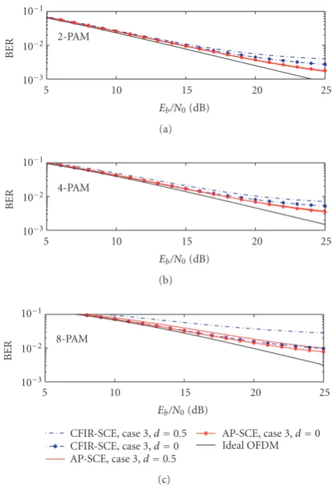
zero delay. Figure 9, however, shows a semi-analytic BER comparison of the two subcarrier equalizer structures for 2M=256 subchannels when the effect of time synchroniza-tion error is considered. Simulasynchroniza-tions were carried out with a quasi-static channel model based on the extended ITU-R
5 10 15 20 25 2-PAM
10 3 10 2 10 1
BER
Eb/N0(dB) (a)
5 10 15 20 25
4-PAM
10 3 10 2 10 1
BER
Eb/N0(dB) (b)
5 10 15 20 25
CFIR-SCE, case 3,d=0.5 CFIR-SCE, case 3,d=0 AP-SCE, case 3,d=0.5
AP-SCE, case 3,d=0 Ideal OFDM 8-PAM
10 3 10 2 10 1
BER
Eb/N0(dB)
(c)
Figure9: Semi-analytic BER in AP-SCE and CFIR-SCE. Parameter
d=timing offset/subcarrier symbol interval.
and 50% of the subcarrier symbol interval, respectively. It is seen that with 0 timing offset, CFIR-SCE and AP-SCE have very similar performance. However, AP-SCE is clearly more robust in the presence of timing offset. Especially with high-order modulations, the performance of CFIR-SCE is signif-icantly degraded when the timing error approaches half of the subcarrier symbol interval. AP-SCE is very robust in this sense, and the results demonstrate that FBMC with AP-SCE can be operated without timing synchronization prior to the receiver filter bank.
Figure 10 shows the signal-to-interference ratio (SIR) performance in case of an ideal channel with timing off -set only. Here,Case 2AP-SCE includes only the first-order complex allpass and phase rotation; the real allpass does not have any effect in this case. Figure 10 was obtained in the 2M = 256 subcarrier case, but it was observed that with other filter bank sizes, the behavior in terms of relative tim-ing offset is very similar. It is seen that Case 3 CFIR-SCE gives clearly better performance than simple phase rotation (Case 1), and with timing offsets approaching half of the symbol interval,Case 2AP-SCE has 3 dB better performance thanCase 3CFIR-SCE. This is in accordance with the find-ings in [34], where it is observed that allpass IIR structures
0 0.1 0.2 0.3 0.4 0.5
AP-SCE, case 2 CFIR-SCE, case 3 AP/CFIR-SCE, case 1
Timing offset/symbol interval 0
5 10 15 20 25 30 35 40
SIR
(dB)
Figure10: Semi-analytic SIR due to timing phase offset in AP-SCE and CFIR-SCE in an ideal channel.
provide performance gain in fractional delay compensation compared to FIR structures with similar complexity.
5.2. Performance comparisons with channel coding
5.2.1. Channel model, system parameters, and
OFDM reference
We have also carried out full simulations in time domain comparing cyclic prefix OFDM and FBMC. It was of par-ticular interest to evaluate the performance of FBMC with AP-SCE and CFIR-SCE per-subcarrier equalizers and to ex-plore the potential spectral efficiency gain. Time-variant ra-dio channel impairments were modeled based on the ex-tended ITU-R Vehicular-A PDP [33] (maximum excess de-lay of 2.51μs). This upgraded channel model has been shown to improve the frequency correlation properties when compared to the original PDP, making it better suited for evaluation of wideband transmission with frequency-dependent characteristics. Mobile velocity of 50 km/h and carrier frequency of 5 GHz were assumed. With sampling rate of 26.88 MHz (7× WCDMA chip rate), 616 subcar-riers of 1024 in OFDM and 84/168/672 subchannels of 128/256/1024 in FBMC were activated to obtain systems with the same effective bandwidth of 18 MHz (at 40 dB below passband level). This corresponds to subchannel bandwidths of 26.25 kHz and 210/105/26.25 kHz, respectively. 2-, 4-, and 8-PAM modulations were considered for FBMC whereas QPSK, 16-QAM, and 64-QAM were used for OFDM. The FBMC design used roll-offρ = 1.0 and overlapping factor
was performed using low-density parity check (LDPC) cod-ing [35]. The maximum number of iterations in iterative de-coding was set to ten. About 10% overhead for pilot carri-ers is assumed in OFDM and similar overhead for training sequences in FBMC. OFDM has 41.67μs overall symbol du-ration, with 2.53μs guard interval and 1.04μs raised-cosine roll-offfor spectral shaping. Both systems have a single zero power subcarrier in the middle of the spectrum to facilitate receiver implementation. The information bit rates in the two systems were approximately matched using code rates of
R=3/4 andR=2/3 for OFDM and FBMC, respectively. Bits for a single frame to be transmitted were coded in blocks of 3348 and 3990 bits, respectively, after which all the coded bits of a frame were randomly interleaved before bits-to-symbols and symbols-to-subcarriers mappings. The resulting num-ber of source bits in a fixed frame duration of 250μs are 5022 and 5320 for QPSK/OFDM and 2-PAM/FBMC, respectively. Ideal channel estimation was assumed for both OFDM and FBMC modulations. Simulation result statistics are based on 5000 transmitted frames for each of which an independent realization of the channel model was applied. MSE optimiza-tion criterion was used to derive the amplitude equalizer parameters.
5.2.2. Coded results
Figures11(a),11(b), and11(c)show the obtained results for 2-PAM/QPSK, 4-PAM/16-QAM, and 8-PAM/64-QAM com-parisons, respectively. Coded frame error rate (FER) and BER are shown as a function of required energy per source bit to noise spectral density-ratio. Due to the absence of time do-main guard interval and reduced frequency dodo-main guard-bands, higher spectral efficiency in FBMC is achieved. This excess transmission capacity can be used to transmit more redundant data (lower coding rate) while maintaining sim-ilar information data rate compared to OFDM. This turns into favor of FBMC in the FER/BER performance compari-son as somewhat less energy in FBMC is sufficient to result in similar error probability compared to OFDM. Alignment of the performance curves forK=3 andK=5 inFigure 11(a) indicates that at least in narrowband interference-free con-ditions, FBMC design withK = 3 (and possibly evenK =
2) provides sufficient performance with reduced complexity compared toK=5.
5.2.3. Effect of AP-SCE structure and parameters
The ability of AP-SCE/CFIR-SCE equalizer to compensate for mildly frequency selective subchannel responses is clearly visible in the simulation results. FBMC of 2M = 256 sub-channels with Case 3 AP-SCE/CFIR-SCE follows the per-formance curves obtained with the structure consisting of 2M = 1024 subchannels with Case 1 equalizer. So, great reduction in the number of subchannels required to cover the 18 MHz signal band can be achieved with higher-order AP-SCE/CFIR-SCE structures. In case of 2-PAM modula-tion even a filter bank with 2M = 128 subchannels can be
considered. For 4-PAM and 8-PAM, 2M=256 subchannels are required to keep the performance benefit with respect to the OFDM reference.
5.3. Performance with nonlinear power amplifier
The ratio between the maximum instantaneous power of a signal and its mean power (PAPR) is proportional to the number of subcarriers and also depends on the modulation constellation used. This is a matter of concern when the sig-nal passes through a nonlinear device such as the power am-plifier (PA). In this situation, signal components of diff er-ent instantaneous power might be amplified differently, in-troducing distortion to the signal and causing spectral re-growth to the bands adjacent to the signal. In this section, we focus on the spectral regrowth caused by a PA on FBMC and OFDM with similar parameters as in the time domain BER simulations. We apply time domain raised-cosine win-dowing of 28 samples to the OFDM signal in order to assure attenuation of 40 dB for the signal at 9 MHz from the carrier frequency. Therefore, the overall 40 dB bandwidth for OFDM and FBMC is 18 MHz. The PA follows the solid state power amplifier (SSPA) model that can be found in [36]. Only am-plitude nonlinearity is taken into account. The amam-plitude gain is given by
po= pi
1 +pi/ psat
2, (34)
where pi and po are the amplitude of the PA input signal
and output signal, respectively, and psatdenotes the satura-tion voltage of the PA. The spectral regrowth is measured as a function of the input back-off(IBO) of the input sig-nal at the amplifier. InFigure 12 we show the regrowth of the spectra of FBMC (dashed lines) and OFDM (continuous lines). For FBMC we simulate IBOs that are 1.2 dB higher than for OFDM. This reflects the fact that for a similar coded BER performance we can use an FBMC signal with 1.2 dB less power than OFDM. We can see from the figure, that it is of advantage to be able to use a weaker signal, since close to the desired passband we obtain less spectral regrowth. At more distant frequencies, the OFDM spectrum decays faster because the useful bandwidth is smaller than the useful band-width in FBMC (16.2 MHz versus 17.6 MHz). OFDM with a comparable useful bandwidth (672 active subcarriers) has a spectral decay profile similar to FBMC’s. Moreover, at the same IBOs and same useful bandwidths, both systems show very similar regrowth curves.
5.4. Frequency offset
In multicarrier transmissions, frequency offsets (e.g., due to Doppler and inaccuracy of local oscillators in the transmis-sion chain) introduce ICI. In case of a fixed frequency offset in OFDM, the SIR due to the resulting ICI is given by [37]
SIR= 1
sin(πΔf)2Nc−1
p=0,p=Nc/21/
Ncsin
π(p+Δf)/Nc
2,
Dotted lines< > K=3 Solid lines< > K=5 Dashed lines< >CFIR
0 5 10 15 20
Eb/N0(dB)
Pe
FER
BER
OFDM, QPSK
FBMC, 2M=128, AP, Case 3 FBMC, 2M=128, CFIR, Case 3 FBMC, 2M=256, AP, Case 3 FBMC, 2M=256, CFIR, Case 3 FBMC, 2M=1024, AP, Case 1
Upgraded ITU-R Veh-A@ 50 km/h, 5000 frames, 2-PAM/QPSK, LDPC coding
10 4 10 3 10 2 10 1 100
(a)
0 5 10 15 20
Eb/N0(dB)
Pe
FER
BER
OFDM, 16-QAM
FBMC, 2M=128, CFIR, Case 3 FBMC, 2M=128, AP, Case 3 FBMC, 2M=256, AP, Case 3 FBMC, 2M=256, CFIR, Case 3 FBMC, 2M=1024, AP, Case 1
Upgraded ITU-R Veh-A@ 50 km/h, 5000 frames, 4-PAM/16-QAM, LDPC coding
10 4 10 3 10 2 10 1 100
(b)
0 5 10 15 20
Eb/N0(dB)
Pe
FER
BER
OFDM, 64-QAM
FBMC, 2M=128, AP, Case 3 FBMC, 2M=256, AP, Case 3 FBMC, 2M=256, CFIR, Case 3 FBMC, 2M=1024, AP, Case 1
Upgraded ITU-R Veh-A@ 50 km/h, 5000 frames, 8-PAM/64-QAM, LDPC coding
10 4 10 3 10 2 10 1 100
(c)
Figure11: Coded FER and BER performance: (a) 2-PAM/FBMC and QPSK/OFDM; (b) 4-PAM/FBMC and 16-QAM/OFDM; and (c) 8-PAM/FBMC and 64-QAM/OFDM.
where Nc andΔf are the number of subcarriers and
fre-quency offset, respectively. The effects of frequency offsets in FBMC were tested with a simple simulation experiment by measuring the mean squared error in symbol detection with a set of fixed frequency offsets. The results are shown and compared to the OFDM performance inFigure 13. Here
Nc=256 for both systems.
30 20 10 0 10 20 30 Frequency (MHz)
80 70 60 50 40 30 20 10 0 10
PSD
(dB)
FB, no PA Windowed OFDM no PA
FB, IBO=1.2 dB FB, IBO=7.2 dB FB, IBO=13.2 dB FB, IBO=19.2 dB
Windowed OFDM, IBO=0 dB Windowed OFDM, IBO=6 dB Windowed OFDM, IBO=12 dB Windowed OFDM, IBO=18 dB Figure12: Spectral regrowth due to PA nonlinearity.
It can be seen fromFigure 13 that for a given relative (with respect to subcarrier spacing) frequency offset, the FBMC SIR performance is slightly better but within 2 dB from the OFDM performance. Since FBMC allows signifi-cantly wider subcarrier spacing, the relative frequency off -sets are smaller, and there is a clear performance benefit for FBMC in terms of frequency offset effects. This indicates also a potential for better performance in case of fast fading.
5.5. Complexity
In this subsection, a rough evaluation of the computational complexity of FBMC is presented, using a simple complexity measure: the number of real multiplications required to de-tect a symbol. We focus on the receiver side where the OFDM FFT or FBMC analysis bank and the equalizer are the main processing blocks. Channel estimation and calculation of the equalizer coefficients are not included in this evaluation.
One of the most efficient algorithms for implement-ing DFT is the split radix FFT algorithm [18], taking
M(log2(M)−3) + 4 real multiplications for a block ofM
complex samples. In the OFDM case, 3 real multipliers are enough to do the complex multiplication to equalize each of the used subcarriers.
In the FBMC case, the FFT-based algorithm presented in [26] is the most efficient one to implement the oversam-pled analysis bank in terms of multiplication rate. It requires 2M(2K−2 + log2(M)) real multiplications for a block ofM
high-rate samples. In an efficient implementation, the AP-SCE subcarrier equalizers take 2, 5, and 7 real multiplications in Cases1,2, and3, respectively, per detected real symbol. Alternatively, the 3-tap CFIR-SCE structure takes 6 real mul-tiplications per detected real symbol.
0 0.05 0.1 0.15 0.2
Frequency offset as a fraction of subcarrier spacing 5
10 15 20 25 30 35 40
SIR
(dB)
OFDM FBMC
Figure13: SIR due to frequency offset in OFDM and FBMC.
Table1: Multiplications in receiver per one detected complex sym-bol in OFDM and per two detected real symsym-bols in FBMC.
Case 1 Case 3
OFDM, 1k-FFT 10 —
FBMC,K=2, 2M=128, AP-SCE 20 30 FBMC,K=5, 2M=256, AP-SCE 34 44 FBMC,K=2, 2M=128, CFIR-SCE 20 28 FBMC,K=5, 2M=256, CFIR-SCE 34 42
For a fair comparison, we calculate the overall number of multiplications per detected complex symbol in the OFDM case and per two detected real symbols in the FBMC case. For simplicity, it is assumed that all the subcarriers are in use. The resulting overall multiplication rates with the two extreme cases of FBMC-complexity are shown inTable 1.
It is observed that with this complexity measure, FBMC is more complex than the basic OFDM system. However, the implementation of FBMC is yet quite realistic with today’s efficient digital signal processors or dedicated very large scale integration (VLSI) hardware. It is expected that there are a lot of possibilities to optimize the EMFB implementation in dedicated hardware, using short coefficient word-lengths, sums of powers of two implementations for coefficients, and so forth.
Furthermore, it can be noted that due to the larger block-size, OFDM requires significantly bigger data memory and coefficient storage in processor-based implementations.
![SYNTHESIS, CHARACTERIZATION AND CHELATING PROPERTIES OF POLY[AZO (1 NAPTHOL)]](data:image/gif;base64,R0lGODlhAQABAIAAAP///wAAACH5BAEAAAAALAAAAAABAAEAAAICRAEAOw==)