%WHFK5DPDQDQGDWLUWKD(QJLQHHULQJ&ROOHJH
0WHFK9DVWKVDO\D,QVWLWXWHRI6FLHQFHDQG
7HFKQRORJ\9/6,
Abstract—Single error correction (SEC) codes are widely used to protect data stored in memories and registers. In some ap-plications, such as networking, a few control bits are added to the data to facilitate their processing. For example, flags to mark the start or the end of a packet are widely used. Therefore, it is important to have SEC codes that protect both the data and the associated control bits. It is attractive for these codes to provide fast decoding of the control bits, as these are used to determine the processing of the data and are commonly on the critical timing path. In this brief, a method to extend SEC codes to support a few additional control bits is presented. The derived codes support fast decoding of the additional control bits and are therefore suitable for networking applications.
Index Terms—Error correction codes, high-speed networking, memory, single error correction (SEC).
I. INTRODUCTION
N
ETWORKING applications require high-speed process-ing of data and thus rely on complex integrated circuits[1]. In routers and switches, packets typically enter the device through one port, are processed, and are then sent to one or more output ports. During this processing, data are stored and moved through the device [2].
Reliability is a key requirement for networking equipment such as core routers [3]. Therefore, the stored data must be protected to detect and correct errors. This is commonly done using error-correcting codes (ECCs) [4]. For memories and registers, single error correction (SEC) codes that can correct 1-bit errors are commonly used [5], [6].
One problem that occurs when protecting the data in net-working applications is that, to facilitate its processing, a few control bits are added to each data block. For example, flags to mark the start of a packet (SOP), the end of a packet (EOP), or an error (ERR) are commonly used [7]. These flags are used to determine the processing of the data, and the associated control logic is commonly on the critical timing path. To access the control bits, if they are protected with an ECC, they must first be decoded. This decoding adds delay and may limit the overall
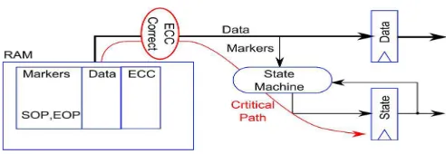
Fig. 1. Typical packet data storage in a networking application.
Then,aSECcodecanprotectadatablockusing8parity checkbits,andanotherSECcodecanprotectthe3control bits using 3 parity check bits. This option provides independentdecodingofdataandcontrolbitswhichreduces thedelaybutrequiresadditionalparitycheckbits.Another optionistouseasingleECCtoprotectboththedataand controlbits.Protecting128+3bitsrequiresonly8parity checkbits,thussaving3bitscomparedtotheuseofseparate ECCs.However,inthiscase,thedecodingofthecontrolbits ismorecomplexandincursmoredelay.
In this brief, a method to extend a SEC code to also protect a few additional control bits is proposed. In the resulting codes, the control bits can be decoded using a subset of the parity check bits. This reduces the decoding delay and makes them suitable for networking applications. To evaluate the method, several codes have been constructed and implemented. They are then compared with existing solutions in terms of decoding delay and area.
The rest of this brief is organized as follows. In Section II, the problem of control bit decoding in networking applications is described. In Section III, the proposed method to construct the codes to support fast decoding of the control bits is presented. The proposed scheme is evaluated for some relevant examples in Section IV. Finally, the conclusion and some ideas for future work are presented in Section V.
II. DATAPROTECTION INNETWORKINGAPPLICATIONS
Modern networking equipment supports data rates that range from 10 to 400 Gbit/s, and terabit rates are expected in the near future [8]. The clock frequencies used in current ASICs are typically in the range of 300 MHz to 1 GHz, and the clock frequencies in FPGAs are typically lower (under 400 MHz). To support these high data rates, on-chip packet data buses are wide, with typical widths between 64 and 2048 bits [9], [10].
%WHFK--,QVWLWXWHRI,QIRUPDWLRQ7HFKQRORJ\
0WHFK9DVWKVDO\D,QVWLWXWHRI6FLHQFHDQG
7HFKQRORJ\9/6,
Fig. 2. Parity check matrix for a minimum-weight SEC code that protects 128 data bits.
Fig. 3. Parity check matrix for a minimum-weight SEC code that protects 128 data and 3 control bits.
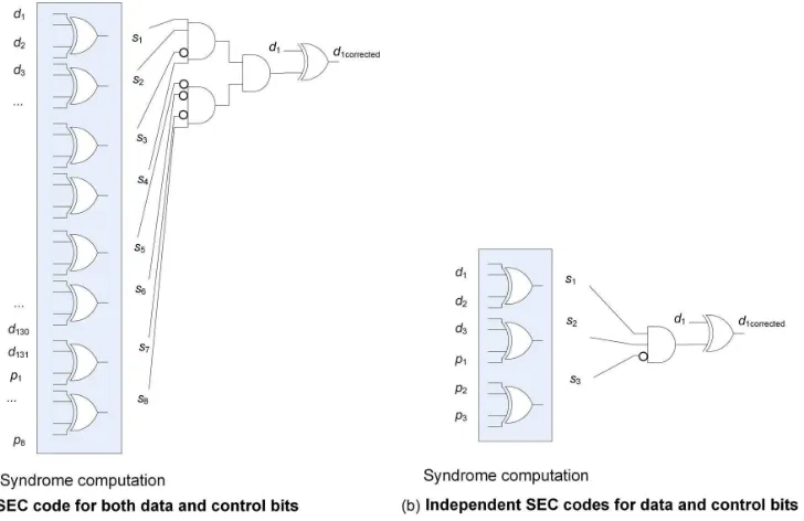
Fig. 4. Decoding of a control bit for single and independent SEC codes for data and control. (a) SEC code for both data and control bits. (b) Independent SEC codes for data and control bits.
Packet data must frequently be stored in RAMs, e.g., in FIFOs for adapting processing rates. When storing packet data, it is necessary to delineate the packet boundaries. In the abso-lute simplest case, each segment on the bus can be delineated with a single EOP marker. The next valid segment is then assumed to be the start of the following packet. In practice, designers also use a SOP marker to explicitly mark the start of packets. There are also many cases in packet processing where a packet is in error and it must be dropped. To mark such errored packets, an additional control signal (ERR) may be required [7]. As mentioned in the introduction, from an error protection perspective, it is attractive to store the data and the markers in a single wide memory, as shown in Fig. 1. In this way, relatively fewer ECC bits are required. The problem with this approach is when the data are read out. Typically, the markers feed into a state machine that controls the reading of the subsequent data. For example, the state machine may need to read out a single packet (up to an EOP), or it may need to read out a fixed
number of bytes of data (e.g., deficit round robin scheduler). The critical timing path then consists of the ECC correction logic, followed by the state machine logic, as shown in red. With a traditional Hamming SEC code, as the data bus increases in width, the number of layers of logic required to decode the syndrome and perform correction also increases. Circuit designers frequently observe critical timing on the signal paths related to the correction of the markers which feed downstream state machines. For this reason, special ECC codes which can provide a fast decode of the small number of marker bits are extremely attractive.
In some cases, it is sufficient for the system to deal with the packet data with a granularity of the block size. This would be the case, for example, when the data are simply being transferred from one location to another. However, in other cases, it is important to know the packet data size with a byte resolution. This would be the case when the bit rate is important (scheduling and policing) or when maximum transfer unit
Fig. 5. Proposed parity check matrix for a SEC code that protects 128 data and 3 control bits.
length checks are performed. The simple SOP and EOP markers are not sufficient to know the exact packet size; thus, it may be necessary to store additional marker bits called EOPSIZE, which indicate how many of the bytes in the EOP transfer are valid. Note that it is always assumed that all transfers prior to the EOP are complete. Thus, on a 128-bit data bus, additional 4 bits of EOPSIZE may be required, bringing the total number of marker bits to 7 (SOP, EOP, ERR, and EOPSIZE[3:0]).
III. PROPOSEDMETHOD TODESIGN THECODES
As discussed in the introduction, the goal is to design SEC codes that can protect a data block plus a few control bits such that the control bits can be decoded with low delay. As mentioned before, the data blocks to be protected have a size that is commonly a power of two, e.g., 64 or 128 bits. To protect a 64-bit data block with a SEC code, 7 parity check bits are needed, while 8 are enough to protect 128 bits. In the first case, there are27
= 128possible syndromes, and therefore, the SEC code can be extended to cover a few additional control bits. The same is true for 128 bits and, in general, for a SEC code that protects a data block that is a power of two. This means that the control bits can also be protected with no additional parity check bits. This is more efficient than using two separate SEC codes (one for the data bits and the other for the control bits) as this requires additional parity check bits. The main problem in using an extended SEC code is that the decoding of the control bits is more complex. To illustrate this issue, let us consider a 128-bit data block and 3 control bits. The initial SEC code for the 128-bit data block has the parity check matrix shown in Fig. 2. This code has a parity check matrix with minimum total weight and balanced row weights to minimize encoding and decoding delay [4]. Three additional data columns can be easily added to obtain a code that protects the additional control bits. For example, the matrix in Fig. 3 can be used, in which three additional columns (marked as control bits) have been added to the left.
The problem is that now, to decode the 3 control bits, we need to compute the 8 parity check bits and compare the results against the columns of the control bits. This is significantly more complex than the decoding of an independent SEC code for the three control bits. The decoding of a bit in each case is shown in Fig. 4, and the difference in complexity is apparent.
As discussed earlier, our goal is to simplify the decoding of the control bits while using a single SEC code for both data and control bits. To do so, the first step is to note that, in some cases, SEC decoding can be simplified to check only some of the syndrome bits. One example is the decoding of constant-weight SEC codes proposed in [11]. In this case, only the syndrome
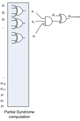
Fig. 6. Bit decoding of a control bit in the proposed SEC code.
TABLE I
MINIMUMNUMBER OFPcdBITS FOR128AND256 DATABITS
bits that have a 1 in the column of the parity check matrix need to be checked. This simplifies the decoding for all bits but, in most cases, requires additional parity check bits. In our case, the main focus is to simplify the decoding of the control bits as those are commonly on the critical path. To do so, the parity check bits can be divided in two groups: a first group that is shared by both data and control bits and a second that is used only for the data bits. Then, the decoding of the control bits only requires the recomputation of the first group of parity check bits. This scheme is better illustrated with an example. Let us consider a 128-bit data block and 3 control bits protected with 8 parity check bits. Those 8 bits are divided in a group of 3 shared between data and control bits and a second group of 5 that is used only for the data bits. To protect the control bits, the first three parity check bits can be assigned different values for each control bit, and the remaining parity check bits are not used to protect the control bits. The rest of the values are used to protect the data bits, and for each value, different values of the
Fig. 7. Proposed parity check matrix for a SEC code that protects 128 data and 7 control bits.
remaining five parity check bits can be used. In this example, the first group has 3 bits that can take 8 values, and three of them are used for the columns that correspond to the control bits. This leaves 5 values that can be used to protect the data bits. The second group of parity check bits has 5 bits that can be used to code 32 values for each of the 5 values on the first group. Therefore, a maximum of5×32 = 160data bits can be protected. In fact, the number is lower as the zero value on the first group cannot be combined with a zero or a single one on the second group as the corresponding column would have weight of zero or one. In any case, 128 data bits can be easily protected. An example of the parity check matrix of a SEC code derived using this method is shown in Fig. 5. The three first columns correspond to the added control bits. The two groups of parity check bits are also separated, and the first three rows are shared for data and control bits, while the last five only protect the data bits. It can be observed that the control bits can be decoded by simply recomputing the first three parity check bits. In addition, the zero value on these three bits is also used for some data bits. This means that those bits are not needed to recompute the first three parity check bits.
The decoding of one of the control bits is illustrated in Fig. 6. It can be observed that the circuitry is significantly simpler than that of a traditional SEC code (see left part of Fig. 4). This will be confirmed by the experimental results presented in the next section.
The method can also be used to protect more than three control bits. In a general case, let us consider that we need to protect ddata bits and c control bits usingpparity check bits. Then, p is divided in two groups pcd and pd. The first group is shared between control and data bits, and the second is used only for the data bits. The number of data bits that can be protected with this scheme can be calculated as follows. The number of combinations of the first group available to be used to protect the data bits is2P cd
−c. For each of those, up to2P d
values can be used, giving a total of(2P cd
−c)·2P d. However, for the zero value, the combinations of the second group with weight zero or one cannot be used, so pd+ 1 should be subtracted. Similarly, for thepcdvalues with weight one on the first group, the zero value on the second group cannot be used as the resulting column would have weight one. Therefore,pcdshould also be subtracted, giving a total of (2P cd
−c)·2P d−(pd+ 1)−pcd. This is the number of data bits that can be protected in addition to the control bits. As the number of control bits increases,pcdmust also be increased to be able to protect the block of data bits with the same number of parity check bits. This is illustrated in Table I for 128 and 256 data bits. Increasingpcdmakes the decoding of control bits more complex; therefore, the minimum value should be used.
TABLE II
ASIC CIRCUITAREA(µM2)FOR3 ADDITIONALCONTROLBITS
TABLE III
ASIC CIRCUITDELAY(NS)FOR3 ADDITIONALCONTROLBITS
As an example, the parity check matrix to protect 128 data and 7 control bits is shown in Fig. 7. It can be observed that, in this case, more bits are needed in the first group, making the decoding of the control bits slightly more complex. However, the control bits can still be decoded using only four syndrome bits instead of the eight bits required in a traditional SEC code. Finally, it should be noted that the proposed scheme increases the miscorrection probability for control bits in case of double errors. This is due to the use of only a subset of bits for the decoding of the control bits.
IV. EVALUATION
To assess the benefits of the proposed scheme, it has been implemented for 64, 128, and 256 data bits considering both 3 and 7 additional control bits. The codes implemented for the case of 128 data bits correspond to the ones in Figs. 5 and 7. The encoders and decoders are compared with minimum-weight SEC codes that have balanced row minimum-weight (given in Fig. 3 for the case of 128 data bits and 3 control bits). These SEC codes should provide the minimum decoding delay for a traditional SEC code.
To evaluate the proposed codes for an ASIC implementation, all of the designs have been implemented in HDL and then mapped using Synopsis DC to a 45-nm ASIC library [12]. For the decoders, the synthesis was configured to allocate the majority of the effort to the minimization of delay on the
TABLE V
ASIC CIRCUITDELAY(NS)FOR7 ADDITIONALCONTROLBITS
control bits as that is the main design goal. For the encoders, the tool was configured to minimize delay on all bits. In all cases, identical synthesis constraints were applied to both the proposed codes and the minimum-weight codes. The circuit area and delay have been evaluated.
The results for the case of three additional control bits are shown in Tables II and III. The tables also show the results for the minimum-weight SEC codes. In this case, the reduction of the decoding delay of the control bits is in the range of 12%–18%. This shows the potential of the proposed scheme to reduce the critical path. The circuit area is similar to that of the minimum-weight SEC codes, in some cases slightly lower and in some slightly higher.
The proposed codes do have an impact on the decoding delay for the data bits. For the decoders, the added delay on data bits is significant for most word sizes. However, as discussed in the introduction, the major design goal is to reduce the decoding delay of the control bits as these typically determine the critical timing path.
The results for the case of seven control bits are shown in Tables IV and V. The proposed codes require a circuit area for both the encoder and the decoder similar to that of the minimum-weight codes. In terms of delay, decoding of the data bits is slower. On the other hand, the proposed codes are able to reduce the decoding delay of the control bits by approximately 9%–11%. This reduction is smaller than that for the three control bits case. This is expected as the number of parity bits(pcd)used to decode the control bit increases (from three to four) and so does the decoder complexity. Therefore, the benefits of the proposed scheme decrease as the number of control bits increases.
In summary, the proposed method can be used to reduce the decoding delay of the control bits, especially when the number of control bits is small.
number of parity check bits as existing SEC codes and therefore do not require additional cost in terms of memory or registers. To evaluate the benefits of the proposed scheme, several codes have been implemented and compared with minimum-weight SEC codes.
The proposed codes are useful in applications, where a few control bits are added to each data block and the control bits have to be decoded with low delay. This is the case on some networking circuits. The scheme can also be useful in other applications where the critical delay affects some specific bits such as in some finite-state machines. Another example is arithmetic circuits where the critical path is commonly on the least significant bits. Therefore, reducing the delay on those bits can increase the overall circuit speed. The use of the proposed scheme for those applications beyond networking is an interest-ing topic for future work. It may be possible to apply the idea of modifying the matrix of the code to enable fast decoding of a few bits to more advanced ECCs that can correct multiple bit errors. Finally, the scheme can also be extended to support more control bits by using one or two additional parity check bits. This would provide a solution to achieve fast decoding without using two separate codes for data and control bits.
REFERENCES
[1] P. Bosshart et al., “Forwarding metamorphosis: Fast programmable match-action processing in hardware for SDN,” in Proc. SIGCOMM, 2013, pp. 99–110.
[2] J. W. Lockwoodet al., “NetFPGA—An open platform for gigabit-rate network switching and routing,” inProc. IEEE Int. Conf. Microelectron. Syst. Educ., Jun. 2007, pp. 160–161.
[3] A. L. Silburt, A. Evans, I. Perryman, S.-J. Wen, and D. Alexandrescu, “Design for soft error resiliency in Internet core routers,”IEEE Trans. Nucl. Sci., vol. 56, no. 6, pp. 3551–3555, Dec. 2009.
[4] E. Fujiwara,Code Design for Dependable Systems: Theory and Practical Application. Hoboken, NJ, USA: Wiley, 2006.
[5] C. L. Chen and M. Y. Hsiao, “Error-correcting codes for semiconductor memory applications: A state-of-the-art review,”IBM J. Res. Develop., vol. 28, no. 2, pp. 124–134, Mar. 1984.
[6] V. Gherman, S. Evain, N. Seymour, and Y. Bonhomme, “Generalized parity-check matrices for SEC-DED codes with fixed parity,” inProc. IEEE On-Line Test. Symp., 2011, pp. 198–20.
[7] Ten Gigabit Ethernet Medium Access Controller, OpenCores. [Online]. Available: http://opencores.org/project/ethmac
[8] P. Zabinski, B. Gilbert, and E. Daniel, “Coming challenges with terabit-per-second data communication,” IEEE Circuits Syst. Mag., vol. 13, no. 3, pp. 10–20, 3rd Quart. 2013.
[9] UltraScale Architecture Integrated Block for 100 G Ethernet v.14. LigCOREIP Product Guide. PG165, Xilinx, San Jose, CA, USA. Jan. 22, 2015.
[10] OpenSilicon Interlaken ASIC IP Core. [Online]. Available: www.open-silicon.com/open-silicon-ips/interlaken-controller-ip/
[11] P. Reviriego, S. Pontarelli, J. A. Maestro, and M. Ottavi, “A method to construct low delay single error correction (SEC) codes for protecting data bits only,”IEEE Trans. Comput.-Aided Design Integr. Circuits Syst., vol. 32, no. 3, pp. 479–483, Mar. 2013.
[12] J. E. Stine et al. “FreePDK: An open-source variation-aware design kit,” inProc. IEEE Int. Conf. Microelectron. Syst. Educ., Jun. 2007, pp. 173–174.