ISSN 2286-4822 www.euacademic.org
Impact Factor: 3.4546 (UIF)
DRJI Value: 5.9 (B+)
Android Based Wireless Live Human Detection
Robot for Rescue Operations
IMRAN KHAN Department of Computer Engineering Balochistan University of Information Technology Engineering &
Management Science (BUITEMS) Quetta, Pakistan
Abstract:
Intelligent mobile robots and cooperative multi- agent robotic systems can be very efficient tools to speed up search and research operations in remote areas. Robots are also useful to do jobs in areas and in situations that are hazardous for human. They can go anywhere that is not reachable by humans and can go into gaps and move through small holes that are impossible for humans and even trained dogs. Our preliminary aim in this project is to build a robot communication to detect live humans, robot control by smart phone through Bluetooth. Once the people are positioned, it directly gives a visual alerts to rescue teamover Bluetooth technology on smart phone.
Key words: Robotics Technology, Android based Robotics, Bluetooth, Sensors, Artificial Intelligence, Rescue Operations, Android Application, PR Sensor, Wireless IP Camera, Live Streaming
intelligent robots using new robots control devices, new drives and advanced control algorithms. This Project deals with live personal detection robot which is based on 8 bit Microcontroller PIR sensor is used to detect alive humans. The project is mainly used in the DEBRIS for rescue. All the above systems are controlled by the Microcontroller.
PROBLEM STATEMENT:
In destructed environments it is impossible to detect live humans who need help and many of them lose their lives as a result. Detection by rescue workers becomes time consuming and due to vast area that gets affected it becomes more difficult. In our country rescue operations are performed by humans and trained dogs which is very risky and time consuming and as a result we loss precious life. In past we have seen such incidents in our country for example Karachi Air Base attack in which seven men who were trapped in store room lost their lives by no immediate rescue that is because of slow rescue operation.
Our project proposes a robotic vehicle that moves in the destructed area and helps in identifying the live people. Hence precious life can be saved by timely detection in natural calamities even without the help of large number of rescue operator.
MATERIALS & METHODS:
control algorithms. Our project generally based on the concept of Spy robotics especially for detecting live humans who need help in disastrous areas and security purposes. Where our goal is to replace human work with machine. In such areas where human approach is not possible or we can say difficult. Where risk is extreme or in danger killing areas.
Flow Chart & Algorithm:
Step 1: Start Step 2: Initialize micro controller Step 3: Initialize motors
Step 4: Initialize sensors Step 5: Monitor sensors
Step 6: If person detected Show Status
Step 7: If obstacle detected Show status Step 8: If bomb detected Show Status Step 9: If fire detected Show status
Step 10: If earthquake detected Show status
Step 11: Monitor sensors Step 12: Stop
METHODOLOGY:
PIR sensor:
motion can be detected by checking for a rapid change in the surrounding IR patterns. When motion is detected the PIR sensor will give signal to microcontroller and then send message to android phone through Bluetooth technology. We are also using ultrasonic sensor, metal detector, humidity and temperature sensor, vibration switch module to make the robot more intelligent.
Microcontroller:
ATMEGA328 is the microcontroller used in this system. Signals from sensors are given to the microcontroller and this microcontroller will digitize the signal and send it to the android phone through Bluetooth. The controller has properties like inbuilt ADC, essential to get the signals from the different sensors. By this the microcontroller that is used in this project has some extra advantages.
Android Application:
Designing an android app to control the forward and backward movement of robot by phone. This will be done by Bluetooth module. It has the ability of giving information about detection. Thus detection of alive human is showed as a pop up message to the user.
DESIGN CONSIDERATIONS:
System Structure:
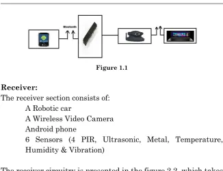
of the vehicle while we have camera monitoring front, left and right side of vehicle. The video camera fastened with the robotic car will send real time video signals to our monitoring device i.e. monitor. The video camera is wireless having a range of over 200 ft. radius. After watching the video on the display, the operator may make his own decision and can take an action accordingly. After the user has made his decision, he can send the control commands through serial communication to the micro controller that processes the digital data input. The user can watch the real time video through a software called “SUPER TV pro”. The Environment Monitoring robot system consists of a transmitter, a receiver and a video camera. The communication between receiver and transmitter is wireless i.e. IP communication.
The video camera is wireless and works on radio frequency. The receiver circuitry is the heart of the system which moves the robot to left, to right, forward and reverse. The user will monitor all the activities of the robot; in fact user can control the robot. The user can control the robot by sending the control commands through serial communication (Bluetooth) to the transmitter circuitry.
Control Section:
Figure 1.1
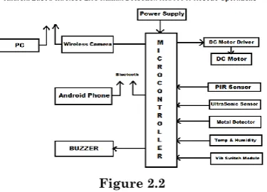
Receiver:
The receiver section consists of: A Robotic car
A Wireless Video Camera Android phone
6 Sensors (4 PIR, Ultrasonic, Metal, Temperature, Humidity & Vibration)
The receiver circuitry is presented in the figure 2.2, which takes the control commands from the transmitter of the control section through Bluetooth Transceiver. Four motors are associated to the robotic car and the receiver circuitry such that motors move the robot in forward, reverse, left and right direction. The ATMEGA328 microcontroller of the receiver section is programmed in C language. The speed of the motors can be varied by varying the duty cycle of the PWM of the ATMEGA328 micro controller. Greater the duty cycle of the PWM greater will be the speed of the motor.
Figure 2.2
Arduino Uno R3:
The Arduino UNO R3 is a microcontroller board built on the ATmega328. It consists of 14 digital input/output pins (of which 6 used as PWM outputs), 6 analog inputs, a 16 MHz crystal oscillator, a USB connection, a power jack, an ICSP header, and a reset button. It has everything needed to support the microcontroller; simply associate it to a computer with a USB cable or power it with an AC-to-DC adapter or battery to get ongoing.The UNO contrasts from all previous boards because it does not practice the FTDI USB-to-serial driver chip.
Extra properties next with the REV3 version are:
1: ATmega16U2 in its place of 8U2 as USB-to-Serial converter.
2: 1.0 pinout: additional SDA and SCL pins for TWI communication positioned close to the AREF pin and two further new pins placed close to the RESET pin, the IOREF that permit the shields to adjust to the voltage given from the board and the second one is a not associated pin, which is set aside for future determinations.
3: Durable RESET circuit.
the up-to-date in sequences of USB Arduino boards, besides the orientation model aimed at the Arduino platform.
Technical specifications:
Microcontroller ATmega328
Operating Voltage 5V
Input Voltage (suggested) 7-12V
Input Voltage (maximum) 6-20V
Digital I/O Pins 14
PWM Digital I/O Pins 6
Analog Input Pins 6
DC Current per I/O Pin 40 mA
DC Current for 3.3V Pin 50 mA
Flash Memory 32 KB
Flash Memory for Boot loader 0.5 KB
SRAM 2 KB
EEPROM 1 KB
Clock Speed 16 MHz
Length 68.6 mm
Width 53.4 mm
Weight 25 g
Communication:
A Software Serial library permits for serial communication on every of the Uno's digital pins. The ATmega328 also supports I2C (TWI) and SPI communication. The Arduino software contains a Wire library to shorten use of the I2C bus.
Programming:
The Arduino Uno could be encoded with the Arduino software. Choose "Arduino Uno from the Tools > Board menu (according to the microcontroller on your board). The ATmega328 on the Arduino Uno come from pre marked with a boot loader that lets you to upload fresh code to it deprived of the use of an exterior hardware programmer. It converses via the original STK500 protocol (C header files). We can also avoid the boot loader and program the microcontroller over the ICSP (In-Circuit Serial Programming) header with Arduino ISP or alike. The ATmega16U2 (or 8U2 in the rev1 and rev2 boards) firmware source code is accessible. The ATmega16U2/8U2 is overloaded with a DFU boot loader, which can be triggered by:
1: On Rev1 boards: concerning the solder jumper on the back of the board (close the map of Italy) and then rearranging the 8U2.
2: On Rev2 or future boards: here is a resistor that dragging the 8U2/16U2 HWB line to ground, creating it at ease to place into DFU mode.
We can formerly use Atmel's FLIP software or else the DFU programmer (Mac OS X and Linux) to burden a fresh firmware. Or we can use the ISP header with an exterior programmer.
Physical Characteristics:
space amongst digital pins 7 and 8 is 160 mil (0.16"), not an equal multiple of the 100 mil positioning of the other pins.
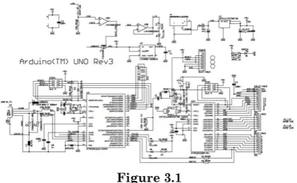
Arduino Uno R3 Schematic:
Figure 3.1
Power Supply:
A power supply is an electronic device that supplies electric energy to an electrical load. The major function of a power supply is to transform one form of electrical energy to another and, as a result, power supplies are sometimes mentioned to as electric power converters. Some power supplies are discrete, stand-alone devices, whereas others are manufactured into larger devices along with their loads.
Rover 5 Robot Platform:
Rover 5 is a new breed of tracked robot chassis designed specifically for students and hobbyist. Unlike conventional tracked chassis’s the clearance can be adjusted by rotating the gearboxes in 5-degree increments. “Stretchy” rubber treads maintain tension as the clearance is raised. Inside of the chassis are 4 noise suppression coils at the bottom and a battery holder that accepts 6x AA batteries (not included). It is recommended to use NiMh batteries as they last longer and have a higher current output than alkaline batteries.
Each gearbox has an 87:1 ratio and includes an optical quadrature encoder that gives 1000 pulses over 3 revolutions of the output shaft. The chassis can be upgraded to include four motors and encoders making it ideal for mecanum wheels.
SPECIFICATION:
1. Motor rated voltage: 7.2V 2. Motor stall current: 2.5A
3. Output shaft stall torque: 10Kg/cm 4. Gearbox ratio: 86.8:1
5. Encoder type: Quadrature
6. Encoder resolution: 1000 state changes per 3 wheel rotations
7. Speed: 1Km/hr
8. Four motors
9. Four encoders
10. Encoder interface: Red = +5V
Black = 0V
Vero board:
Vero board is a circuit prototyping board somewhere between solder less breadboards and printed PCBs. It allows you to make a more permanent circuit, which has more reliable connections than with breadboard, but without the expense of etching or ordering printed PCBs. It consists of strips of metal on a side of a board and a grid of holes spaces 0.1" (2.54mm) apart. This means you can solder most types of non-surfance mount ICs, resistors, capacitors etc onto them. All boards are 1.6mm thick with copper thickness of 35um. Hole grid: 2.54 x 2.54 mm., hole diameter: 1.02 mm.
Features:
1. Ideal for hard wiring or discrete components 2. Range of standard sizes
3. Choice of hole sizes and grid pitch
Sensors:
We are using multiple sensors in our project which will tell us about the situation of surroundings.
1. PIR Sensor 2. Metal Sensor 3. Vibration Sensor
PIR Sensor:
The PIR Sensor senses the motion of a human body by the change in surrounding ambient temperature when a human body passes across. It makes possible high-performance IR radiation detection at room temperature, while cost and low power consumption make it attractive for security applications. Tracking human targets with such a system has been described in figure 5, but little attention to date has been paid to walking, which can also be employed for purposes of identification and scene surveillance in security applications. It can also be used for tracking multiple persons.
Metal Sensor:
Metal detectors work by transmitting an electromagnetic field from the search coil into the ground. Any steel things (targets) within the electro-magnetic area will become empowered and retransmit an electro-magnetic area of their own. The detector’s search coils gets the retransmitted area and signals the customer by generating a focus on reaction.
Vibration Switch Module:
This module is used for detecting vibration i-e changes in surroundings. This switch is OFF in the resting state, when external force to touch and to achieve a proper vibration, meet the appropriate speed or from the (partial) heart conductive pin will momentarily conduction (ON) status, make changes in electric property and disappear when the external force electric property open (OFF) state is restored.It is omnidirectional, any angle can trigger job.
Temperature & Humidity Sensor:
This library use DHT11 sensor to read temperature and humidity on at mega micro. Setup the data port connected to the micro pin, and calls the function to get humidity and temperature.
Ultrasonic Sensors:
Ultrasound receptors (also known as transceivers when they both deliver and get, but more generally called transducers) work on a concept similar to mouth or sonar, which assess features of a focus on by decoding the reflects from stereo or audio surf respectively. Effective ultrasonic receptors produce high regularity audio surf and assess the replicate which is obtained back by the indicator, calculating the time period between delivering the indication and getting the replicate to figure out the range to an item. Inactive ultrasonic receptors are generally mics that identify ultrasonic disturbance that is present under certain conditions.
Wireless Camera:
Wireless cameras are proving very popular among modern security consumers due to their low installation costs (there is no need to run expensive video extension cables) and flexible increasing options. Wireless cameras can be mounted/installed in places previously not available to standard wired ones. In addition to use and convenience of access, wireless security camera allows users to leverage broadband wireless internet to provide seamless video streaming over-internet.
1. Camera is fixed on the top of robot. 2. Camera will get the video
3. Then transmit the video through IP transmitter. 4. Receiver will receive the video.
5. Through USB analog TV stick receive will send video to PC
7. Operating frequency is 2.4GH. 8. Working range is 100 ft.
Working Principle:
The PIR Sensor senses the motion of a human body by the change in surrounding ambient temperature when a human body passes across. Then it turns on the lighting load to which it is connected. The lighting load remains on until it senses motion. Once the motion is seized it switches off the lighting load. During the night, the LUX adjustment knob allows you to adjust the luminosity based on which the lighting load will either switch on/off automatically.
The pyroelectric infrared (PIR) sensor makes possible high-performance IR radiation detection at room temperature, while cost and low power consumption make it attractive for security applications. Tracking human targets with such a system has been described in figure 5, but little attention to date has been paid to walking, which can also be employed for purposes of identification and scene surveillance in security applications.
When humans walk, the motion of various parts of the body, including the torso, arms, and legs, produces a characteristic signature. Much work on motion analysis as a behavioral biometric has used video cameras to stream large amounts of data from which the identity of the person of interest can be extracted in a computationally expensive way. A continuous-wave radar has been developed to record the signature corresponding to the walking human gait. A new method has been proposed by which the features of motion are represented by the processed content of the temporal signal, generated by humans crossing the field of view (FOV) of the PIR sensor module.
determined by shape and IR emissivity of the skin at every point. Combined with idiosyncrasies of carriage, heat will uniquely impact a surrounding sensor field, even while the subject follows a prescribed path. By measuring the response thus generated within the FOV of a sensor module, it is possible to model data to create a code vector that uniquely identifies the person.
RESULTS AND DISCUSSION:
This paper contains two sections. One is Robot section and the other is Control section. In robot section, the sensors about the corresponding parameters are made to available. In the Control section, the parameters are shown on android phone. In Robot and control sections, microcontroller forms the control unit. In this system, a robot is fixed with motors. A microcontroller is used to control all tasks. According to the motor jobs the ROBOT will operate in specified directions. The detection of parameters is finished in a continuous way and the detected value is conveyed using the Bluetooth module to the android phone. Movable camera is capable of transmitting live video streaming to PC; it will transmit live signals through wireless radio frequency to analyze condition of alive humans.
CONCLUSION:
REFERENCES:
[1] Seethai, A., Azha Periasamy, and S. Muruganand. "Rescue Robotics Using Artificial Intelligence."
[2] Vijayaragavan, Mr. SP, and B. Tech. "Live Human
Detecting Robot for Earthquake Rescue
Operation." International Journal of Business Intelligent 2, no. 01.]
[3] Sharad, Rupnar Pallavi, and P. R. Thorat. "Live Human Detecting Robot for Earthquake Rescue Operation."
[4]. Mr. M. Arun Kumar, Mrs. M. Sharmila “Wireless Multi Axis ROBOT for Multi-Purpose Operations”, Department
of ECE, SVCET & JNT University Anantapur, India
[5] Robert L.Boylestad and Louis Nashelsky, “Electronic Devices and Circuit Theory”, 8th Edition, 2006.
[6] Miyama, S.; Imai, M.; Anzai, Y.; "Rescue Robot under disaster Situation: position Acquisition with Omni-directional Block Diagram
[7] George Bekey,” Autonomous Robots: From Biological Inspiration to Implementation and Control”, MIT Press, Cambridge, MA, 2005
[8] Mr. M. Arun Kumar, Mrs. M. Sharmila ”Wireless Multi Axis ROBOT for Multi-Purpose Operations”, Department of ECE, SVCET & JNT University Anantapur.
[9] Robert L.Boylestad and Louis Nashelsky, “Electronic Devices and Circuit Theory”, 8th Edition, 2006.
[10] Pete Miles & Tom Carroll, Build Your Own Combat Robot, (2002).