ISSN (Print) : 2320 – 3765 ISSN (Online): 2278 – 8875
I
nternational
J
ournal of
A
dvanced
R
esearch in
E
lectrical,
E
lectronics and
I
nstrumentation
E
ngineering
(An ISO 3297: 2007 Certified Organization)
Website: www.ijareeie.com
Vol. 6, Issue 12, December 2017
GSM Based Electricity Theft Identification
System
Jayati Routh1, Subhamay Sarkar2
Assistant Professor, Dept. of ECE, Siliguri Institute of Technology, India1 Assistant Professor, Dept. of ECE, Siliguri Institute of Technology, India2
ABSTRACT: Electrical energy is very important in our daily life and a spine of the industry. With the increasing need of power electricity theft has become a big concern. Detecting and eradicating such crimes with the assistance of the developing scientific field is the “need of the hour”. This paper provides a comprehensive tool to prevent electricity theft which is very simple to understand and easy to implement. It includes three sections- detecting, displaying in LCD and transmitting through GSM. The proposed system will be hidden in such meters and as soon as an attempt is made to open or tamper the system, it will send a SMS to the control unit of electricity board. The Block diagram is given below
KEYWORDS: GPS, GSM, LCD, microcontroller
I.INTRODUCTION
Electricity theft is a very common problem in our country, where population is very high and the use of electricity is tremendous. In India, every year increasing number of electricity thefts occurs across domestic electricity connection and as well as industrial electricity supply.
The most common way of theft is by BYPASSING THE METER using a piece of wire, people simply bypass the electricity meter which is counting the current units by placing a wire before and after the meter reading unit, or by TAMPERING the seal which is used in the electricity meter. The proposed system will be hidden in such meters and as soon as an attempt is made to open or tamper the system, it will send a SMS to the control unit of electricity board.
Proposed System: The proposed system will be hidden in such meters and as soon as an attempt is made to open or tamper the system, it will send a SMS to the control unit of electricity board. The Block diagram is given below-
ISSN (Print) : 2320 – 3765 ISSN (Online): 2278 – 8875
I
nternational
J
ournal of
A
dvanced
R
esearch in
E
lectrical,
E
lectronics and
I
nstrumentation
E
ngineering
(An ISO 3297: 2007 Certified Organization)
Website: www.ijareeie.com
Vol. 6, Issue 12, December 2017
The circuit uses ATMEL 8051 family Microcontroller to communicate with the GSM modem to send the SMS, and the theft detecting sensor which is basically a touch sensor in our project but the sensor part can be changed with a variety of other sensors, if the sensor senses any human interference then it sends a signal to the microcontroller, which quickly processes the information and The GSM modem sends a SMS to the pre-programmed Mobile Number.
The basic part of the project of ours is the tampering of the meter by using a touch sensor or any sensor which will report the abnormality to the microcontroller by giving a high logic and then the microcontroller which is a brain to this system will give a high logic to the pins in which the GSM modem is connected and then the data is transferred serially after which the GSM is active and will send the message of theft detection to the registered mobile number that is pre-programmed in the coding part of the microcontroller. The LED is also connected to the pin of the microcontroller as we can be sure that the microcontroller is working fine. This is the main theme of our project, whereas, we can add many more features further in this project i.e. a relay circuit, if theft is detected then the relay acts and will cut-off the main source, we can add a current transformer and a comparator so as to compare the value of the source and after the meter and if there is theft by hooking then the sensor acts on it by giving a high logic.
II.DESCRIPTION OF BLOCK DIAGRAM
1. GSM Modem: A GSM modem is a specialized type of modem which accepts a SIM card, and operates over a subscription to a mobile operator, just like a mobile phone. From the mobile operator perspective, a GSM modem looks just like a mobile phone.
When a GSM modem is connected to a computer, this allows the computer to use the GSM modem to communicate over the mobile network. While these GSM modems are most frequently used to provide mobile internet connectivity, many of them can also be used for sending and receiving SMS and MMS messages.
2. Touch Sensor: A touch sensor primarily works when an object or individual gets in physical contact with it. Unlike a button or other more manual control, touch sensors are more sensitive, and are often able to respond differently to different kinds of touch, such as tapping, swiping and pinching. Touch sensors are used in consumer tech devices such as smart phones and tablet computers. Typically, touch sensors are used as a means to take input from the user. Each physical stroke that a touch sensor records is sent to a processing unit/software that processes it accordingly.
3. 16x2 LCD Display Module: 16×2 LCD is named so because; it has 16 Columns and 2 Rows. There are a lot of combinations available like, 8×1, 8×2, 10×2, 16×1, etc. But the most used one is the 16×2 LCD; hence we are using it here. All the above mentioned LCD display will have 16 Pins and the programming approach is also the same and hence the choice is left to you. Below is the Pinout and Pin Description of 16x2 LCD Module. The LCD can work in two different modes, namely the 4-bit mode and the 8-bit mode. In 4 bit mode we send the data nibble by nibble, first upper nibble and then lower nibble. For those of you who don’t know what a nibble is: a nibble is a group of four bits, so the lower four bits (D0-D3) of a byte form the lower nibble while the upper four bits (D4-D7) of a byte form the higher nibble. This enables us to send 8 bit data. Whereas in 8 bit mode we can send the 8-bit data directly in one stroke since we use all the
4. Power Supply: Power supply is a reference to a source of electrical power. A device or system that supplies electrical or other types of energy to an output load or group of loads is called a power supply unit.
Voltage regulator: A voltage regulator is an electricity regulation device designed to automatically convert voltage into a lower, usually direct current (DC), constant voltage.
MAX232: The MAX232 is an integrated circuit first created in 1987 by Maxim Integrated Products that converts
signals from a TIA-232 (RS-232) serial port to signals suitable for use in TTL-compatible digital logic circuits. The MAX232 is a dual transmitter / dual receiver that typically is used to convert the RX, TX, CTS, RTS signals.
ISSN (Print) : 2320 – 3765 ISSN (Online): 2278 – 8875
I
nternational
J
ournal of
A
dvanced
R
esearch in
E
lectrical,
E
lectronics and
I
nstrumentation
E
ngineering
(An ISO 3297: 2007 Certified Organization)
Website: www.ijareeie.com
Vol. 6, Issue 12, December 2017
The first one is to perform input/output operations and the second one is used to implement special features of the microcontroller like counting external pulses, interrupting the execution of the program according to external events, performing serial data transfer or connecting the chip to a computer to update the software. Each port has 8 pins, and will be treated from the software point of view as an 8-bit variable called 'register', each bit being connected to a different Input/output pin.
Software Used: We have used the Keil uVision software to build the target and compile the HEX code file which is needed to burn in the Microcontroller.
III.OPERATION OF THE CIRCUIT
The below given diagram of the circuit was made using Proteus and was simulated in the same software. The working principle of this project is referred with this diagram.
The Microcontroller used in our circuit is AT89S52 which is manufactured by ATMEL. It belongs to the 8051 family. The Crystal Oscillator used in this circuit is of value 11.0592 MHz which gives the Microcontroller the external pulses required for the working of the project.
The Data bus of the LCD (D0 – D7) is connected with the microcontroller via PORT 2 in a 8 bit mode as it is faster than the usual 4 bit mode. The RS, RW and EN Pin of the LCD is connected with the microcontroller via PORT 1.0, PORT 1.1 and PORT 1.2 respectively. Potentiometer of value 10KOhm is connected in VSS and VEE and one with the ground to vary the Contrast of the LCD. VDD Pin of the LCD is connected with the voltage of 5V.
Similarly with the PORT 1.4 a LED is connected so that when someone tries to tamper the Meter the LED glows and it remains off if NO THEFT is detected i.e. if the meter remains in idle position without human interference. In our case we have used a Switch button in case of a touch sensor for simulation process, one can use any sensor i.e. Touch sensor, IR sensor etc just for the sensing part and is connected with the PORT 3.5 of the Microcontroller.
The GSM MODEM we have used here is SIM900A and we don’t need the externally placed MAX 232 chip as the modem has inbuilt RS232 chip incorporated. The RXD port of the microcontroller which is PORT 3.0 is connected with the TXD Pin of the GSM Module and the TXD Pin of the microcontroller which is PORT 3.1 is connected with the RXD Pin of the GSM module.
PIN No. 31 of the microcontroller is connected with the VCC i.e. 5V and is common with the PIN No. 40 of the microcontroller which also should be connected with the VCC for supplying voltage to the microcontroller. PIN No. 20 of the microcontroller is connected with the ground. A reset switch is connected with the RST PIN of the microcontroller which is Pin No. 9 so as to reset the function of the microcontroller.
As told earlier in the introduction, the basic principle of this project is to sense the tampering of the Digital meter i.e. if anyone tries to tamper the seal then the sensor plays its part i.e. PORT 3.5 (which is already in a high state) by sending a low pulse to the microcontroller and then according to the delay in the program used in the microcontroller. The microcontroller senses the low pulse and then the program executes within a short time by sending a high pulse to the PORT 1.4 in which the LED is connected and then the LED glows, that means if the LED is glowing the program has started to execute and by means of serial mode of transfer the GSM modem sends a SMS to the pre-programmed mobile no. used in the program by the maker and then it will restart its process that is it will send a SMS only one time, the second SMS will be sent only when the Sensor part senses abnormal activity.
IV.RESULT AND DISCUSSION
ISSN (Print) : 2320 – 3765 ISSN (Online): 2278 – 8875
I
nternational
J
ournal of
A
dvanced
R
esearch in
E
lectrical,
E
lectronics and
I
nstrumentation
E
ngineering
(An ISO 3297: 2007 Certified Organization)
Website: www.ijareeie.com
Vol. 6, Issue 12, December 2017
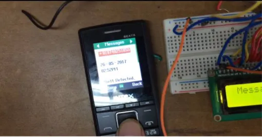
The images with short description of process are given below-
Figure 2: Theft Detection
Part 1: As discussed earlier, if the sensor is touched the microcontroller will respond to its high logic and will detect the theft and will display in it the LCD.
Figure 3: GSM modem part
ISSN (Print) : 2320 – 3765 ISSN (Online): 2278 – 8875
I
nternational
J
ournal of
A
dvanced
R
esearch in
E
lectrical,
E
lectronics and
I
nstrumentation
E
ngineering
(An ISO 3297: 2007 Certified Organization)
Website: www.ijareeie.com
Vol. 6, Issue 12, December 2017
Part 3: The message which is sent to the respective mobile no. shows the message as THEFT DETETED and we can program it adding the Consumer ID no. or anything which is relevant we just need to change the program section. As we know that this project is just limited to the tampering of the meter using a sensor and then the SMS is sent to the respective mobile no. we can add a various components like relay circuit to cut off the main line if the theft is detected and we can also read the units that can be sent to the Electricity board and accordingly when a message is sent from the registered mobile no. to the GSM modem i.e. the SIM associated with it we can control the theft we can also use a Current transformer in the pole and then the electricity meter for the theft which is common that is the direct line by hooking the current transformer sends the value and then the comparator checks the value and can sense the theft caused by the hooking technique. There is a lot more we can do to control the theft. Additionally we can add a buzzer too which will make a sound if theft is detected.
We would like to progress this project further for the hooking theft using current transformer and a relay circuit which will cut-off the main line if the theft is detected by the system.
Conclusion: The project model reduces the manual manipulation work and theft .Use of GSM in our system provides the numerous advantages of wireless network systems. The government saves money by the control of theft in energy meter and also more beneficial for customer side and the government side. Cost wise low when compared to other energy meter without automatic meter reading and theft control. The project better suits for displaying information in long distances, and the information can be send, alter any time according to user requirement.
REFERENCES
[1] R. Jiang, H. Tagaris, A. Lachsz, M. Jeffrey, "Wavelet Based Feature Extraction and Multiple Classifiers for Electricity Fraud Detection", Proc. of IEEE/PES T&D Conference and Exhibition 2002, vol. 3, pp. 2251-2256.
[2] C. R. Paul, "System loss in a Metropolitan utility network", IEEE Power Engineering Journal, pp. 305-307, Sept. 1987.
[3] I. E. Davidson, A. Odubiyi, M. O. Kachienga, B. Manhire, "Technical Loss Computation and Economic Dispatch Model in T&D Systems in a Deregulated ESI", IEEE Power Eng. Journal, Apr. 2002.
[4] T. B. Smith "Electricity theft: A comparative analysis" Energy Policy vol. 32 pp. 2067-2076 2004.
[5] A. Kumar D. D. Saxena "Decision priorities and scenarios for minimizing electrical power loss in an India power system network" Electrical Power Components and Systems vol. 31 pp. 717-727 2003
[6] A. H. Nizar Z. Y. Dong M. Jalaluddin M. J. Raffles "Load Profiling Non-Technical Loss Activities in a Power Utility" Proc. of First International Power and Energy Conference (PECON) Nov. 2006.
[7] M. A. Ram M. Shrestha "Environmental and utility planning implications of electricity loss reduction in a developing country: A comparative study of technical options" International Journal of Energy Research vol. 22 pp. 47-59.