Voltage Profile Improvement by Capacitor
Placement and Control in Unbalanced Distribution
Systems Using Differential Evolution Algorithm
A.Hemasekhar
1, Chevireddy Harika
2Associate professor, H.O.D, Dept. of EEE, S.V.P.C.E.T, PUTTUR, ANDHRAPRADESH, India 1 PG Student [EPS], Dept. of EEE, S.V.P.C.E.T, PUTTUR, ANDHRAPRADESH, India 2
ABSTRACT:One of the most important methods in loss reduction and controlling the voltages of distribution systems is the utilization of the fixed and switched capacitors. To do this, real modelling of the system in actual operational conditions including unbalanced or balanced loading and for actual feeder structure, ie, radial/meshed configuration, are required. In this paper, a new technique for finding the optimal values of the fixed and switched capacitors in the distribution networks with above properties based on the differential evolution algorithm is presented. For this purpose, the modelling of the loads at different load levels are simulated with low voltage and medium voltage capacitors that are available on the market. Regarding the above factors in addition to the various parameters in the optimization problem, DE Algorithm is used to find the best and real optimal network with the best rate for the capacitors.
KEYWORDS: unbalanced distribution networks, ,DE Algorithm, capacitor placement, fuzzy expert system.
I.INTRODUCTION
One of the most effective and useful methods in re-ducing the power losses of distribution networks is uti-lization of optimal capacitor placement. By using shunt capacitors, the reactive power needed for loads is pro-vided so that besides the reduction of losses the voltage profile of nodes is also improved. There are, of course, nu-merous difficulties in optimal placement of capacitors in the purpose of reducing losses. These problems include:
a) non-clarity of the behavior of feeders’ loads, particularly domestic loads, b) complexity of distribution net-works,
c) uncertainty of electric distribution companies in returning the initial capital expenditure used for capaci-tor placement and
There is also the difficulty of trapping the answer of the problem in a local optimal solution. Moreover, since the capacitor banks contain discontinuous values, solving the problem in a continuous domain and then approximating the results leads to a large error in optimal solution. With due regard to the above problems, the genetic algorithm is a very tool in solving the optimization problems. Fuzzy based solution methods use fuzzy membership functions to model the actual systems. Identification of proper membership function is the most challenging task in the development of fuzzy based solution techniques. Node voltage measures and power loss in the network branches have been utilized as indicators for deciding the location and also the size of the capacitors in fuzzy based capacitor placement methods. he global optimization method is most useful in obtaining the optimal capacitor sizes corresponding to maximum annual savings. In that sense, DE is one of the popular meta-heuristic methods in all the engineering fields. In the second stage, DEA is proposed to find the sizes of the capacitors. The capacitor placement problem is modeled with theobjective function, which maximizes the annual savings. The proposed method is tested on 15-bus, 34-bus, and 69-bus test systems and the results are presented.
II.NEED FOR CAPACITOR PLACEMENT
Distribution systems are the networks that transport the electric energy from bulk substation to many services or loads, thus causes more power and energy losses. Hence there is a need to reduce the system losses. By minimizing the power losses, the system may acquire longer life span and has greater reliability.
Loss minimization in distribution systems has assumed greater significance recently since the trend towards distribution automation will require the most efficient operating scenario for economic viability. Studies have indicated that as much as 13% of total power generated is consumed I2R as losses at the distribution level. Reactive currents account for a portion of these losses. However, the losses produced by reactive currents can be reduced by the installation of shunt capacitors. Effective capacitor installation can also release additional KVAR capacity from distribution apparatus and improve the system voltage profile. Reactive power compensation plays an important role in the planning of an electrical system.
As Distribution Systems are growing large and being stretched too far, leading to higher system losses and poor voltage regulation, the need for an efficient and effective distribution system has therefore become more urgent and important. In this regard, Capacitor banks are added on Radial Distribution system for Power Factor Correction, Loss Reduction and Voltage profile improvement. The amount of compensation provided is very much linked to the placement of capacitors in the distribution system, which is essentially determination of the location, size, number and type of capacitors to be placed in the system.
III.IDENTIFICATION OF OPTIMAL CAPACITOR LOCATIONS USING FUZZY APPROACH
This paper presents a fuzzy approach to determine suitable locations for capacitor placement. Two objectives are considered while designing a fuzzy logic for identifying the optimal capacitor locations. The two objectives are: (i) to minimize the real power loss and (ii) to maintain the voltage within the permissible limits. Voltages and power loss indices of distribution system nodes are modeled by fuzzy membership functions. A fuzzy infe rence system (FIS) containing a set of rules is then used to determine the capacitor placement suitability of each node in the distribution system. Capacitors can be placed on the nodes with the highest suitability. For the capacitor placement problem, approximate reasoning is employed in the following manner: when losses and voltage levels of a distribution system are studied, an experienced planning engineer can choose locations for capacitor installations, which are probably highly suitable. For example, it is intuitive that a section in a distribution system with high losses and low voltage is highly ideal for placement of capacitors. Whereas a low loss section with good voltage is not ideal for capacitor placement. A set of fuzzy rules has been used to determine suitable capacitor locations in a distribution system. In the first step, load flow solution for the original system is require d to obtain the real and reactive power losses. Again, load flow solutions are required to obtain the power loss reduction by compensating the total reactive load at every node of the distribution system. The loss reductions are then, linearly normalized in to a [0, 1] range with the largest loss reduction having a value of 1 and the smallest one having a value of 0. Power Loss Index value for nth node can be obtained using equation 4.
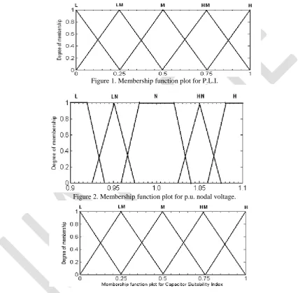
In this paper, two input and one output variables are selected. Input variable-1 is power loss index (PLI) and Input variable-2 is the per unit nodal voltage (V). Output variable is capacitor suitability index (CSI). Power Loss Index range varies from 0 to 1, P.U. nodal voltage range varies from 0.9 to 1.1 and Capacitor suitability index range varies from 0 to 1.Five membership functions are selected for PLI. They are L, LM, M, HM and H. All the five membership functions are triangular as shown in Figure 1. Five membership functions are selected for Voltage. They are L, LN, N, HN and H . These membership functions are trapezoidal and triangular as shown in Figure 2. Five membership functions are selected for CSI. They are L, LM, M, HM and H. These five membership functions are also triangular as shown in Figure 3.
Figure 1. Membership function plot for P.L.I.
Figure 2. Membership function plot for p.u. nodal voltage.
Figure 3. Membership function plot for C.S.I
For the capacitor allocation problem, rules are defined to determine the suitability of a node for capacitor installation. Such rules are expressed in the following form:
IF premise (antecedent), THEN conclusion (consequent).
Sending
End
Receiving
End
V
kV
k+1
V
0V
nY
k1Y
k2P
k+
jQ
kr
k+
jx
k' k
k jQ
P
1 k 1
k jQ
P PnjQn
1
1
Lk
Lk jQ
P
Table I. Decision matrix for determining the optimal capacitor locations
IV.CAPACITOR PLACEMENT PROBLEM
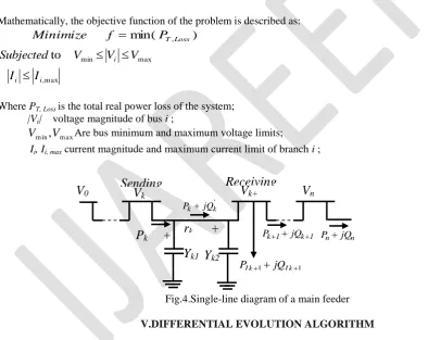
Capacitor placement in the distribution system is to minimize loss of the system, subjected to certain operating constraints and load pattern. For simplicity, the operation and maintenance cost of the capacitor placed in the distribution system is not taken into consideration. The three-phase system is considered as balanced and loads are assumed as time invariant.
Mathematically, the objective function of the problem is described as:
Minimize
f
min(
P
T,Loss)
max min
to
V
V
V
Subjected
i
I
i
I
i,maxWhere PT, Lossis the total real power loss of the system; |Vi| voltage magnitude of bus i ;
V
m in,
V
m axAre bus minimum and maximum voltage limits;Ii,Ii, max current magnitude and maximum current limit of branch i ;
Fig.4.Single-line diagram of a main feeder
V.DIFFERENTIAL EVOLUTION ALGORITHM
DE introduced by Storn and Price[11], is a branch of evolutionary algorithms for optimization problems over continuous domains. In DE, each variable’s value in the chromosome is represented by a real number. DE can be categorized into a class of floating-point encoded evolutionary algorithms.
direction information according to the differentiations among the population. However, the searching behavior of each individual is adjusted by dynamically altering the differentiation’s direction and step length. At each generation, the mutation and crossover operators are applied to individuals to generate a new population. Then, selection takes place and the population is updated.
Implementation of DE
The basic procedure of DE is summarized as follows.
Step 1: Randomly initialize the population of individual for DE.
Step 2: Evaluate the objective values of all individuals, and determine the best individual best it which has the best objective value.
Step 3: Perform mutation operation for each individual according to Eq. 4.3 in order to obtain each individual’s
corresponding mutant vector.
Step 4: Perform crossover operation between each individual and its corresponding mutant vector according to Eq.4.4
in order to obtain each individual’s trial vector.
Step 5: Evaluate the objective values of the trial vectors.
Step 6: Perform selection operation between each individual and its corresponding trial vector according to Eq.4.5so as to generate the new individual for the next generation.
Step 7: Determine the best individual of the current new population with the best objective value. If the objective value of the current best individual is be perturbed, the num better than that of best it, then update best it and its objective value.
Step 8: If a stopping criterion is met, then output bests it and its objective value; Otherwise go back to step 3.
V.SIMULATION RESULTS
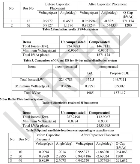
69-Bus Radial Distribution System
Table.1.Optimal candidate locations corresponding to capacitor sizes
Table 2.Simulation results of 69-bus system
Table 3. Comparison of GA and DE for 69-bus radial distribution system
85-Bus Radial Distribution System
Table 4: Simulation results of 85 bus system
Table.5:Optimal candidate locations corresponding to capacitor sizes
No.
Bus No.
Before Capacitor
Placement
After Capacitor Placement
Voltage(p.u) Angle(deg) Voltage(p.u)
Angle(deg)
Q-Cap
(kVAr)
1
18
0.9577
0.4633
0.967594
-0.8221
371.174
2
62
0.9127
1.1170
0.933244
-1.54433
1200
Items
Uncompensated
Compensated
Total losses (Kw).
224.0783
146.7111
Minimum Voltage(p.u)
0.9096
0.9302
Total kVAr placed
-
1571.174
Items
uncompensated
compensated
GA
Proposed DE
Total losses(kW)
224.0783
152.5
146.7111
Minimum Voltage(p.u)
0.9096
0.9291
0.9302
Total kVAr
-
1985
1571.17
Items
Uncompensated
Compensated
Total losses (Kw).
287.2198
112.9067
Minimum Voltage(p.u)
0.8724
0.9300
Total kVAr placed
-
2455.695
No.
Bus No.
Before Capacitor
Placement
After Capacitor Placement
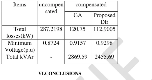
Table 6: Comparison of GA and DE for 85 bus radial distribution system
.
VI.CONCLUSIONS
DE Algorithm is a new and efficient method for the optimization of power distribution systems. A capacitor placement method that employs sensitivity factors and DE as well as simplified power flow formulations to reduce power losses and enhance voltage profile for primary distribution system is presented. The method seeks the most effective buses to install compensation capacitors so that maximum voltage profile to be improved. The sensitivity factors to the buses are effective in reducing the total number of alternatives examined for finding the optimal solution. This method is useful for large distribution system applications.
In this project, the applicability of DE algorithm for solving the capacitor placement problem in large scale distribution system is demonstrated. The results obtained for the example systems considered in this project, indicate that highly near optimum solutions can be achieved when compared to GA method. The DE method places capacitors at less number of locations with optimum sizes and offers much saving in initial investment. The simulation results based on a 169 bus systems and a 85-bus system have produced the best solutions that have been found using a number of approaches available in the technical literature.
REFERENCES
[1] J.J Grainger and S.H.Lee,”Optimum size and location of shunt capacitors for reduction of losses of distribution feeders”, IEEE Trans. On power apparatus and systems, vol. 100, pp. 1105-1118, mar. 1981.
[2] S.H.LEE and J.J Grainger,” Optimum placement of fixed and switched capacitors on primary distribution feeders”. IEEE Trans. On power apparatus systems, vol.100, pp.345-352, jan.1981.
[3] J.J Grainger and S.H.Lee, capacity release by shunt capacitor placement on distribution feeders: A new voltage-dependent model”, IEEE Trans. On power apparatus and systems, vol.101, pp. 1236-1244, may 1982.
[4] Y.BaghzoUZ and S.Ertem. “Shunt capacitor sizing for radial distribution feeders with distorted substation voltages”, IEEE Trans. On power Delivery, vo.5.pp, 650- 657, apr.1990.
[5] J.L.Bala, P.A.Kuntz and R.M.Taylor,”sensitivity-based optimal capacitor placement on a radial distribution feeder”, in Proc. northcon 95 IEEE Technical Application conf., pp.225-230, 1995
[6] S.Sundharajan and A.Pahwa,”Optimal selection of capacitors for radial distribution systems using a genetic algorithm”, IEEE Trans. Onpower systems, vol.9, pp.1499- 1507, aug.1994.
[7] C.T.Su and C.C.Tsai,”a new fuzzy reasoning approach to optimum capacitor allocation for primary distribution systems”, in proc. IEEE on industrial Technology conf., pp.237-241, 1996.
[8] C.T.Su and C.S.Lee,and C.S.Ho,”Optimal selection of capacitors in distribution systems”,in proc. IEEE Power Tech CONF., bpt99-171-42, 1999. [9] L.L Lai and J.T.Ma,”Application of evolutionary programming to reactive power planning-comparison with nonlinear programming approach”, IEEE Trans. Onpower
systems, vol.12, pp.198-204, feb.1997.
[10] K.Y.Lee and F.F.Yang,”Optimal reactive power planning using evolutionary algorithms: A comparative study for evolutionary programming, approach”, IEEE Trans. On power systems, vol.13, pp.101-108, feb.1998.
[11] R.Storn and K.Price,”Minmizing the real functions of the ICEC’96 contest by differential evolution”, in proc. IEEE on evolutionary computation conf., pp842-844, 1996.
[12] K.V.Price, “Differential evolution vs the the functions of the second ICEO”,in proc.1997 IEE Trans.Evolutionary computation, vol.3, pp.22-34,apr.1999.
[13] R.Storn,”System design by constraint adaptation and Differential evolution”, IEE Trans.Evolutionary Computation, vol. 3, pp.22-34, apr.1999. [14] Baghzouz. Y and Ertem S, “Shunt capacitor sizing for radial distribution feeders with distorted substation voltages,” IEEE TransPower Delivery, vol. 5, pp.650–57, 1990.
Items
uncompen
sated
compensated
GA
Proposed
DE
Total
losses(kW)
287.2198 120.75
112.9005
Minimum
Voltage(p.u)
0.8724
0.9157
0.9298
[15] M.Chis, M. M. A. Salama and S. Jayaram, “Capacitor Placement in distribution system using heuristic search strategies,” IEE Proc-Gener, Transm, Distrib, vol, 144, No.3, pp. 225-230, May 1997.
[16] M. E Baran and F. F. Wu, “Optimal Sizing of Capacitors Placed on a Radial Distribution System”, IEEE Trans. Power Delivery, vol. No.1, pp1105-1117, 1989.
[17] Das et al, “Simple and efficient method for load flow solution of radial distribution network,” Electric Power and Energy Systems, vol. 17, No.5, pp.335-346,1995.
[18] D. Das, “Reactive power compensation for radial distribution networks using genetic algorithms,” Electric Power and Energy Systems, vol. 24, pp.573-581. 2002.
[19] Smarajit Ghosh and Karma Sonam Sherpa, “ An Efficient method for Load-Flow Solution of Radial Distribution Networks”, International Journal ofElectrical Power and Energy Systems Engineering, Vol. 1, No. 2, pp. 108-115, 2008
BIOGRAPHY
A.Hema sekhar He received his B.Tech (Electrical and Electronics Engineering) degree from JNTU,Hyderabad, at Sree Vidyaniketan Engineering College, Rangampet; M.Tech (PSOC) from the S.V.University college of Engineering,Tirupati.He is currently working as Associate Professor & Head of the Dept. of Electrical and Electronic Engineering, S.V.P.C.E.T,Puttur. His area of interest power systems, operation and control, distribution systems, electrical machines. ,Power Stability