Scholarship@Western
Scholarship@Western
Electronic Thesis and Dissertation Repository
10-11-2012 12:00 AM
Exploration of Three-dimensional Morphometrics of the Hip Joint
Exploration of Three-dimensional Morphometrics of the Hip Joint
and Reconstructive Technologies
and Reconstructive Technologies
Charys M. MartinThe University of Western Ontario
Supervisor
Timothy D. Wilson
The University of Western Ontario Joint Supervisor Charles L. Rice
The University of Western Ontario Graduate Program in Kinesiology
A thesis submitted in partial fulfillment of the requirements for the degree in Doctor of Philosophy
© Charys M. Martin 2012
Follow this and additional works at: https://ir.lib.uwo.ca/etd
Part of the Medical Anatomy Commons
Recommended Citation Recommended Citation
Martin, Charys M., "Exploration of Three-dimensional Morphometrics of the Hip Joint and Reconstructive Technologies" (2012). Electronic Thesis and Dissertation Repository. 904.
https://ir.lib.uwo.ca/etd/904
This Dissertation/Thesis is brought to you for free and open access by Scholarship@Western. It has been accepted for inclusion in Electronic Thesis and Dissertation Repository by an authorized administrator of
EXPLORATION OF THREE-DIMENSIONAL MORPHOMETRICS OF THE HIP JOINT AND RECONSTRUCTIVE TECHNOLOGIES
(Spine title: 3D Morphometrics of the Hip and Reconstructive Technologies)
(Thesis format: Integrated Article)
by
Charys M. Martin
Graduate Program in Kinesiology
A thesis submitted in partial fulfillment of the requirements for the degree of
Doctor of Philosophy
The School of Graduate and Postdoctoral Studies The University of Western Ontario
London, Ontario, Canada
ii
THE UNIVERSITY OF WESTERN ONTARIO School of Graduate and Postdoctoral Studies
CERTIFICATE OF EXAMINATION
Supervisor
______________________________ Dr. Timothy Wilson
Co- supervisor
______________________________ Dr. Charles L. Rice
Supervisory Committee
______________________________ Dr. Jim Dickey
______________________________ Dr. Aashish Goela
Examiners
______________________________ Dr. Anne Agur
______________________________ Dr. Andrew Nelson
______________________________ Dr. Jamie Melling
______________________________ Dr. Tom Jenkyn
The thesis by
Charys M. Martin
entitled:
Exploration of Three-dimensional Morphometrics of the Hip Joint
and Reconstructive Technologies
is accepted in partial fulfillment of the requirements for the degree of
Doctor of Philosophy
______________________ _______________________________
iii
Abstract
This dissertation is an exploration of three-dimensional (3D) anatomy using the hip joint as the model of study. Very few studies have taken advantage of 3D modelling to assess the features of commercially available software, or to assess the validity and reliability of 3D morphometrics. This dissertation compared three reconstructive software programs to survey user appreciation concerning how 3D anatomical reconstructive software can be utilized and then established the advantages and limitations of 3D measurements in the hip joint. Three main studies are presented: the first, a comparison of three widely available 3D
reconstructive software programs, Amira, OsiriX, and Mimics. This comparison used a decision matrix to outline which software is best suited for construction of 3D anatomical models, morphometric analysis, and building 3D visualization and learning tools. Mimics was the best-suited program for construction of 3D anatomical models and morphometric analysis. For creating a learning tool the results were less clear. OsiriX was very user-friendly; however, it had limited capabilities. Conversely, although Amira had endless potential and could create complex dynamic videos it had a challenging interface. Based on the overall results of study one, Mimics was used in the second and third studies to quantify 3D surface morphology of the hip joint. The second study assessed the validity and reliability of a novel 3D measurement approach of the femoral head (n=45). Study two highlighted the advantages of modelling a convex shape and the advantages of quantifying the proximal femur in 3D. This measurement approach proved to be valid and reliable. The third study assessed the validity and reliability of a similar 3D measurement approach applied to the acetabulum (n=45). This study illustrated the limitations and challenges encountered when quantifying the complex geometry of the concave acetabulum. This measurement approach was reliable, yet the differences between the digital and cadaveric measurements were large and clinically significant. The hip joint is a complex joint that benefits from 3D visualization and quantification; however, challenges surrounding measuring the acetabulum remain.
Keywords
iv
Co-Authorship Statement
The written material in this thesis is the original work of the author. Charys Martin participated in all aspects of the work contained herein: conception of the hypotheses,
conduction of the experiments, and authorship of the manuscripts. The roles of the co-authors are outlined below.
Chapter 3:
This manuscript will be submitted to the Journal of Digital Imaging. C.M. Martin and T.D. Wilson shared in the conception of this research study. All authors on the manuscript, C.M. Martin, T.D. Wilson, C.L. Rice, V.A. Roach, and N. Nguyen, shared in the creation of the methodology of this study. The data for this study was collected, analyzed, and interpreted by C.M. Martin. C.M. Martin prepared the manuscript with inputs from all authors.
Chapter 4:
This manuscript will be submitted to the Journal of Anatomy. C.M. Martin and T.D. Wilson shared in the conception of this research study. All authors on the manuscript, C.M. Martin, T.D. Wilson, C.L. Rice, J.G. Turgeon, and A. Goela, shared in the creation of the
methodology. C.M. Martin and J.G. Turgeon collected data for this study; these data were analyzed and interpreted by C.M. Martin. C.M. Martin prepared the manuscript with inputs from all authors.
Chapter 5:
v
Acknowledgments
My graduate career has been neither easy nor straightforward; however, along the way I have gained knowledge and experience well beyond the scope of this dissertation. The past four years would have impossible without the guidance and support of many advisors and colleagues.
First I would like to thank my supervisors Dr. Timothy Wilson and Dr. Charles Rice. Your mentorship has been invaluable in my development as an academic, and for that I am thankful. Dr. Wilson, thank you for the opportunity to grow independently as a scientist while still providing me with the encouragement and support to succeed. Dr. Rice, thank you for always being available to support and guide me through this process.
To my advisors Dr. Aashish Goela and Dr. Jim Dickey, thank you for expert advice. Dr. Goela, your clinical expertise was invaluable. Dr. Dickey, your insightful comments and constructive criticisms always helped me to look at my work from a different angle and enabled me to broaden my knowledge base. It was a pleasure working with you and I hope that I will have that pleasure again in the future.
I also wish to express my gratitude to the Western University Body Bequeathal Program for the use of the cadaveric specimens; Dr. Cynthia Dunning for the use of your computer lab; Dr. Cesare Romagnoli for your clinical expertise early in the planning process; Kamal Agarwal, Gleb Naboka, and Erin Bussin for your assistance in preparing the cadaveric specimens; and Dr. Chris Lee for your guidance with regards to data analysis.
I am indebted to my student colleagues who have been involved with my projects over the years: James Turgeon, Victoria Roach, Dr. Ngan Nguyen, Jeremy Roth, Lauren Allen, Tamara Stock, and Mike Midgely. Thank you all for taking time to serve as observers, decision-makers, and recorders for my projects, I greatly appreciate it. A special thank you to Sid Bhattacharya for all of your technical support.
vi
anatomy is my passion and I hope that you all gained as much from the Kin 2221 labs as I did. To Gary Lapenski, Dr. Timothy Wilson, Dr. Marjorie Johnson, and Dr. Peter Haase, thank you for showing me what it means to be a great teacher. I aspire to be as engaging and inspiring as all of you one day. Additional thanks to Dr. Marjorie Johnson for being my unofficial advisor; your care and guidance is very much appreciated.
Thank you to the Department of Anatomy and Cell Biology for adopting me into your department for the past four years. To the department’s clinical anatomy students from 2008-2011, thank you for creating such a fun work environment, especially Dr. Ngan Nguyen, Michele Barbeau, and Victoria Roach. You ladies helped me maintain my sanity over the past four years and I would have never been able to get this far without all of your support and love. Thank you for being there to share laughs, cries, and Friday dance parties.
I would like to express my heart-felt gratitude to my family, who has always believed in me, even when I didn’t believe in my self. The love and encouragement provided to me by my whole family has been immeasurable, and has sustained me on my academic journey. Mom and Dad, thank you for instilling in me the drive and determination that enabled me to push through the hard times.
vii
Table of Contents
CERTIFICATE OF EXAMINATION ... ii
Abstract ... iii
Co-Authorship Statement ... iv
Acknowledgments ... v
Table of Contents ... vii
List of Figures ... xiii
List of Appendices ... xv
List of Abbreviations and Terms ... xvi
Chapter 1 ... 1
1. General Introduction ... 1
1.1 Introduction to the Dissertation ... 1
1.2 3D Modelling ... 2
1.3 3D Reconstructive Software Programs ... 3
1.4 3D Modelling and Morphometrics of the Hip Joint ... 3
1.5 The Proximal Femur ... 4
1.6 The Acetabulum ... 5
1.7 Overall Objectives and Aims ... 6
1.8 References ... 6
Chapter 2 ... 11
2 Literature Review ... 11
2.1 Anatomy of the Hip Joint ... 11
2.1.1 The Acetabulum ... 11
2.1.2 The Proximal Femur ... 12
viii
2.3 Hip Instability ... 13
2.3.1 Possible Causes of Hip Instability ... 14
2.3.2 Association of Osteoarthritis with Hip Instability ... 14
2.4 Femoroacetabular Impingement ... 15
2.4.1 Mechanisms of Impingement ... 15
2.4.2 Possible Causes of Femoroacetabular Impingement ... 19
2.4.3 Association of Osteoarthritis with Femoroacetabular Impingement ... 19
2.5 Diagnostic Measurement ... 20
2.5.1 Diagnostic Measurement for Hip Instability ... 20
2.5.2 Diagnostic Measurement for Femoroacetabular Impingement ... 22
2.5.3 Reliability of Measures ... 24
2.5.4 Challenges with Current Measures ... 24
2.6 Treatment ... 25
2.6.1 Treatment of Hip Instability ... 25
2.6.2 Treatment of Femoroacetabular Impingement ... 25
2.7 3D Modelling ... 26
2.7.1 3D Modelling in Measurement ... 26
2.7.2 3D Modelling in Education ... 27
2.8 Why is a Comparison Needed? ... 28
2.9 3D Reconstructive Software Programs ... 29
2.9.1 Amira ... 29
2.9.2 OsiriX ... 30
2.9.3 Mimics ... 31
2.9.4 Previous Assessment of the 3D Reconstructive Software Programs ... 32
2.10 References ... 33
ix
3 Comparison of 3D Reconstructive Technologies used for Morphometric Research and
the Translation of Knowledge ... 41
3.1 Introduction ... 41
3.2 Methods and Materials ... 44
3.2.1 Decision-Makers ... 44
3.2.2 3D Reconstructive Programs ... 45
3.2.3 Assessment ... 45
3.3 Results ... 47
3.3.1 Cost ... 47
3.3.2 System Requirements ... 48
3.3.3 Program Features ... 48
3.3.4 Decision Matrix - Morphometric Research Weighting Scale Results ... 50
3.3.5 Decision Matrix - Educational Features Weighting Scale Results ... 51
3.3.6 Open-ended Comments ... 54
3.3.7 Preference Questionnaire ... 55
3.4 Discussion ... 57
3.4.1 Program Features ... 57
3.4.2 Decision Matrix - Morphometric Research Weighting Scale ... 58
3.4.2.1 Morphometric Research Weighting Scale: 3D Modelling ... 58
3.4.2.2 Morphometric Research Weighting Scale: Measurement Tools 59 3.4.3 Decision Matrix - Educational Weighting Scale ... 60
3.4.3.1 Educational Weighting Scale: 3D Modelling ... 61
3.4.3.2 Educational Weighting Scale: Measurement Tools ... 62
3.4.3.3 Educational Weighting Scale: Educational Features ... 62
3.5 References ... 64
x
4 Validity and Reliability of a Novel 3D Measurement Approach for the Morphology of
the Proximal Femur ... 68
4.1 Introduction ... 68
4.2 Methods and Materials ... 70
4.2.1 Cadaveric Measurements ... 71
4.2.2 Digital Measurements ... 72
4.2.3 Statistical Analysis ... 73
4.3 Results ... 74
4.3.1 Reliability of Femoral Head Surface Measurements ... 74
4.3.1.1 Intraobserver Reliability ... 74
4.3.1.2 Interobserver Reliability ... 75
4.3.2 Validity of Femoral Head Surface Measurements ... 77
4.4 Discussion ... 79
4.5 References ... 82
Chapter 5 ... 86
5 Validity and Reliability of a Novel 3D Measurement Approach for the Morphology of the Acetabulum ... 86
5.1 Introduction ... 86
5.2 Methodology ... 88
5.2.1 Cadaveric Acetabular Measurements ... 89
5.2.2 Digital Acetabular Measurements ... 90
5.2.3 Statistical Analysis ... 91
5.3 Results ... 92
5.3.1 Reliability of Acetabular Surface Measurements ... 92
5.3.1.1 Intraobserver Reliability ... 92
5.3.1.2 Interobserver Reliability ... 93
xi
5.4 Discussion ... 97
5.5 References ... 102
6 General Discussion ... 105
6.1 Introduction ... 105
6.2 3D Modelling ... 105
6.3 3D Reconstructive Software Programs ... 106
6.4 3D Modelling and Morphometrics of the Hip Joint ... 108
6.5 Future Directions ... 110
6.6 Conclusion ... 112
6.7 References ... 113
Appendices ... 115
xii
List of Tables
Table 3.1 - Program information and features ... 48
Table 3.2 - Decision-maker comments regarding each 3D reconstructive software program 54
xiii
List of Figures
Figure 2.1 – Types of FAI. ... 16
Figure 2.2 - FAI pathology during flexion. ... 18
Figure 2.3 - Centre-edge (CE) angle. ... 21
Figure 2.4 - Vertical-centre-anterior (VCA) angle. ... 22
Figure 2.5 - Alpha angle. ... 23
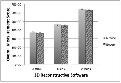
Figure 3.1: Overall novice and experienced scores for each 3D reconstructive program using the morphometric research weighting scale ... 50
Figure 3.2 - Novice and experienced scores, for each 3D reconstructive program using the morphometric research weighting scale, for (A) 3D modelling criteria and (B) measurement tools criteria ... 51
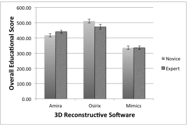
Figure 3.3 - Overall novice and experienced scores for each 3D reconstructive program using the educational features weighting scale ... 52
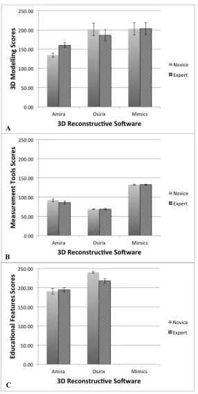
Figure 3.4 - Novice and experienced scores, for each 3D reconstructive program using the educational weighting scale, for (A) 3D modelling criteria, (B) measurement tools criteria, and (C) educational features criteria ... 53
Figure 3.5 - Final questionnaire preferences regarding program interface, 3D modelling features, measurement tools, and educational features ... 56
Figure 4.1 – Measurement of the femoral cadaveric specimens. ... 71
Figure 4.2 - Measurement of the femoral digital models. ... 73
xiv
Figure 4.4 – Bland-Altman plot of intraobserver variability of the (A) femoral cadaveric measures and (B) femoral digital measures. ... 75
Figure 4.5 - Polar graphs of interobserver reliability measurments of the femoral head
surface. ... 76
Figure 4.6 – Bland-Altman Plot of interobserver variability of the (A) femoral cadaveric measures and (B) femoral digital measures. ... 77
Figure 4.7 - Polar graph of mean femoral cadaveric and digital measurements. ... 78
Figure 4.8 - Bland-Altman plot of the difference between the femoral cadaveric and the digital measurements. ... 78
Figure 5.1 - Measurement of the acetabular cadaveric specimens. ... 89
Figure 5.2 - Measurement of the acetabular digital models. ... 91
Figure 5.3 - Polar graphs of intraobserver reliability measurements of the acetabular surface. ... 93
Figure 5.4 – Bland-Altman plots of intraobserver variability of the (A) acetabular cadaveric measures and (B) acetabular digital measures. ... 93
Figure 5.5 - Polar graphs of interobserver reliability measurements of the acetabular surface. ... 94
Figure 5.6 – Bland-Altman plots of interobserver variability of the (A) acetabular cadaveric measures and (B) acetabular digital measures. ... 95
Figure 5.7 - Polar graph of mean acetabular cadaveric measures and digital measures. ... 96
Figure 5.8 - Bland-Altman plot of the difference between the acetabular cadaveric
measurements and the acetabular digital measurements. ... 96
xv
List of Appendices
Appendix A: 3D Reconstructive Software Assessment Form and Final Questionnaire ... 115
Appendix B: Amira Instructional Guide ... 119
Appendix C: OsiriX Instructional Guide ... 128
Appendix D: Mimics Instructional Guide ... 137
Appendix E: Decision Matrix ... 146
Appendix F: Cadaveric Acetabular Measurements with Labra Removed ... 147
Appendix G: Permissions ... 150
xvi
List of Abbreviations and Terms
Abbreviations:
AD – Acetabular Dysplasia
AP View – Anteroposterior Radiographic View
AW – GE’s Advantage Workstation Volume Share 4
CE – Centre-edge Angle
CI – Confidence Interval
CT – Computed-Tomography
DDH - Developmental Dysplasia of the Hip
DICOM – Digital Imaging and Communications in Medicine
FAI – Femoroacetabular Impingement
FEM – Finite Element Modelling
FP View – False Profile Radiographic View
MRI – Magnetic Resonance Imaging
N/A – Not Applicable
OA – Osteoarthritis
ROM – Range of Motion
TIVMI - Treatment and Increased Vision for Medical Imaging
xvii Glossary of Terms:
Acetabular Depth – Measures the relationship of the floor of the fossa acetabuli and the femoral head relative to the ilioischial line
Profunda – The floor of the fossa acetabuli touches or is medial to the ilioischial line
Protrusio – The medial edge of the femoral head is medial to the ilioischial line
Acetabular Inclination – Measures the angle between the face of the acetabular cup and the transverse pelvic axis
Acetabular Version (crossover sign) – Measures the relationship between the anterior and posterior wall of the acetabulum
Anteverted Acetabuli – The anterior wall does not cross the posterior wall of the acetabulum before reaching the lateral edge of the sourcil on an anterior-posterior radiograph
Retroverted Acetabuli – The anterior wall does cross over the posterior wall of the acetabulum before reaching the lateral edge of the sourcil on an anterior-posterior radiograph
Anteroposterior (AP) View – Focus-film distance is 100cm. If possible, the AP view should be obtained with the patient in a standing position with approximately 20° of internal rotation of the lower limbs, to compensate for femoral
anteversion.
Athropathy – A disease of an abnormality of a joint
Capsulorrhaphy – Suture of a tear in a capsule, especially of a joint capsule to prevent recurring dislocation
xviii
Coxa Vara - a deformity of the hip, whereby the angle between the head and the shaft of the femur is reduced to less than 120°
False Profile (FP) View – This radiographic view is obtained with the patient standing and the affected side of the pelvis rotated 65° relative to the film
Femoral Anteversion - A condition where the femoral neck is angled more anteriorly causing the lower extremity to rotate internally
Femoral Head Center – Measures the center of the femoral head on an anterior-posterior radiograph
Lateralized Head Center – The medial aspect of the femoral head was greater than 10mm from the ilioischial line
Femoral Head Sphericity – Measured by applying a reference circle template (Mose templates) on an anterior-posterior radiograph, frog lateral radiograph and/or crosstable lateral radiograph
Non Spherical – The femoral epiphysis extends beyond the margin of the reference circle by 2mm or more
Femoral Head-neck Offset – Measures the concavity of the femoral head-neck junction on an anterior-posterior radiograph, frog lateral radiograph and/or
crosstable lateral radiograph
Ilioischial Line – a line connecting the most lateral aspect of the pelvic brim and the most lateral aspect of the obturator foramen on an anterior-posterior
radiograph
Joint Congruency – Measures the alignment of the arc of the femoral head in relationship to the arc of the acetabulum
Learning – the process of gaining knowledge and/or experience
xix
Model – A representation in three dimensions of an existing person or thing or of a proposed structure
Morphometrics – The quantitative analysis of form (size and shape)
Osteoplasty – Surgical repair or alteration of bone
Osteotomy – Surgical division or sectioning of bone
Reliability - or Precision or Reproducibility is defined as the degree to which the same method produces the same results on repeated measurements
Segmentation – Delineation of anatomical structures and other regions of interest on data sets from three-dimensional imaging modalities, such as computed-tomography and magnetic resonance imaging
Slipped Capital Femoral Epiphysis – refers to a fracture through the femoral head physis (growth plate), which results in slippage of the overlying epiphysis
Tönnis Grade – Classification system to grade osteoarthritic radiographic changes
Validity – or Accuracy is the degree to which an instrument measures the real value of a variable
Chapter 1
1. General Introduction
1.1 Introduction to the Dissertation
This dissertation is an exploration of three-dimensional (3D) anatomy using the hip joint as the main model of study. There are very few studies that have taken advantage of 3D modelling to test the validity and reliability of morphometrics of the hip joint as a basis for clinical applications, or to assess the features of commercially available software for analysis and knowledge transfer of 3D anatomy in general. In this dissertation I have combined these ideas by first taking a broad assessment of software available to aid in understanding how 3D anatomical software can be utilized, and then using the results of the software analysis I have assessed in detail some of the advantages and limitations of 3D measurements in a complex joint. Three main studies are presented: the first, a comparison of three widely available 3D reconstructive software programs and their ability to construct 3D anatomical models, conduct morphometric research with those models, and build 3D visualization and learning tools with the models; the second, a study analyzing the validity and reliability of a novel 3D measurement approach of the femoral head; and the third, a study analyzing the validity and reliability of a similar novel 3D measurement approach of the acetabulum. The order of presentation was chosen so the reader could appreciate the complexities of 3D software available to perform such measurements and to create learning tools to explain the new knowledge regarding the complex hip joint and morphometrics of the hip. Then using this knowledge regarding reconstructive software, the reader can comprehend the advantages and
users who wish to perform these types of morphometric analyses. Chapter Four
highlights the advantages of 3D modelling on a complex, essentially convex shape, the femoral head, and Chapter Five illustrates some of the challenges and limitations
encountered with the congruent portion of the hip joint, the essentially concave and more irregular acetabulum, as compared to the femoral head. This dissertation provides a solid understanding of which 3D software is appropriate to use for morphometric research and education. It provides a foundation to establish a 3D measurement approach for the hip joint as well as enlightening the reader to the complexity of measuring the contours of human anatomy.
1.2 3D Modelling
Since the advent of computed-tomography (CT) and magnetic resonance imaging (MRI), the use of (3D) modelling for education, pre- and post-operative assessment, pre-surgical planning, and measurement has become more prevalent [1-3]. 3D modelling allows optimal visualization of complex anatomical structures and may afford novel and more precise measurement possibilities [4].
1.3 3D Reconstructive Software Programs
In the last few decades, the increased speed and decreased cost of high quality computers has resulted in the greater availability of 3D reconstructive software programs becoming widely available [29]. These programs have been developed for all levels of training, from the general public to medical professionals [30]. A variety of 3D reconstructive software programs have been developed for scientific and educational use; however, no program has become the standard and all of the programs available differ in concept (surface-rendered or volume-rendered), operating system, features, and cost [4, 29].
As a result of the abundance of programs available, studies comparing available software programs have been conducted [4], [31, 32]. However, no study has been completed that evaluates the features of widely available medical imaging programs. Amira, OsiriX, and Mimics are three programs that are widely available, cost effective, and commonly used for morphometric research, building educational tools, operative assessment, and pre-surgical planning [32-43]. A comparison study that objectively assesses these programs for usability, quality of models, features, and time efficiency is required.
1.4 3D Modelling and Morphometrics of the Hip Joint
Noninvasive morphometrics of the hip joint may benefit from 3D modelling. The hip joint is a complex anatomical structure comprised of many surfaces and contours that are three-dimensional in nature. Osteoarthritis (OA) is a major pathological condition that affects the hip joint and is associated with significant disability. Furthermore,
current methods used to define the geometry of the hip use pre-determined measures, typically lengths and angles, on 2D radiographic planes. Fitting these 2D measures to individual variations within a patient population is difficult. These linear measures may not assess the relevant clinical deviations because projecting 3D geometry on to 2D planes does not accurately account for the entire complex joint morphology [6, 10]. Additionally, given the large articular surface area of the hip joint, current 2D imaging methods result in an overlap of the femur and acetabulum and fail to analyze variations in osseous morphology that may be hidden by a hip in situ [11]. Creating 3D models of the morphology allows for the two anatomical structures of the hip joint, the proximal femur and the acetabulum, to be separated for visualization of the entire structure. A valid and reliable 3D measurement approach of the hip joint may assist further research in the area of the hip joint and may lead to a further understanding of the relationship between morphological variations of the hip joint and osteoarthritis. Further understanding of this relationship may lead to more timely diagnoses and treatments of morphological
variations of the hip joint leading to a decrease in severe degenerative disease of the hip.
1.5 The Proximal Femur
One of the areas affected by morphological variations that can lead to OA is the proximal femur. The proximal femur consists of a spherical femoral head that articulates with the acetabulum [12]. Two conditions associated with proximal femur morphology variations are cam-femoroacetabular impingement (cam-FAI) and atraumatic hip instability [13-15].
femoral head and increased anteversion of the femoral neck [16, 23]. The centre-edge (CE) angle [24] and the vertical-centre-anterior (VCA) angle [25] are used to quantify acetabular coverage.
Early detection and appropriate treatment of hip instability and cam-FAI may help prevent the progression of OA [16, 17, 21, 26, 27]. However, the current radiographic parameters for diagnosing these conditions are unreliable [9, 15]. A clear set of
measurements that quantify the entire 3D surface morphology of the proximal femur need to be defined to enable a more reliable diagnosis of early hip disease [15].
1.6 The Acetabulum
The other area affected by morphological variations that can lead to OA is the acetabulum. The acetabulum is comprised of all three pelvic bones; the ilium, the
ischium, and the pubis. The acetabulum is deepened further via the acetabular labrum and the transverse acetabular ligament [23]. Two conditions that define the morphological variations of the acetabulum that are associated with OA are pincer-FAI and hip instability [13-15].
Pincer-FAI is defined as an abnormally deep acetabulum, which results in an
overcoverage of the acetabulum over the femoral head [16-18, 28]. The CE angle, which is used to assess acetabular insufficiency (AD), can also assess acetabular overcoverage (pincer-FAI). Morphological changes caused by AD can also result in a shallow
anteverted acetabulum [16, 23]. The CE angle [24] and the VCA angle [25] are used to quantify insufficient acetabular coverage.
quantify the entire 3D surface morphology of the acetabulum need to be defined to allow for more reliable diagnosis of early hip disease [15].
1.7 Overall Objectives and Aims
The overall objective of this dissertation is to explore the 3D reconstructive software programs available for morphometric and educational purposes and to explore the
morphometrics of the hip joint in 3D. There are three main aims to this dissertation. One: to assess the features, quality, and usability of widely available, cost effective 3D
reconstructive software programs that can be used to measure 3D morphology and help translate knowledge regarding 3D morphology. Two: to create and test the validity and reliability of a 3D measurement approach that quantifies the 3D morphology of the proximal femur. And finally three: to create and test the validity and reliability of a 3D measurement approach that quantifies the 3D morphology of the acetabulum in a way that can be used in conjunction with the proximal femur measurement approach. Thus, the two measurement approaches can quantify each bone separately but essentially can also quantify the articulating bones in relation to one another.
1.8 References
1. Humbert, L., H. Carlioz, A. Baudoin, W. Skalli, and D. Mitton, 3D Evaluation of the acetabular coverage assessed by biplanar X-‐rays or single anteroposterior X-‐ray compared with CT-‐scan. Computer Methods in Biomechanics and Biomedical Engineering, 2008. 11(3): p. 257 -‐ 262.
3. Bale, R. and G. Widmann, Navigated CT-‐guided interventions. Minimally Invasive Therapy & Allied Technologies, 2007. 16(4): p. 196-‐204.
4. Landes, C.A., F. Weichert, P. Geis, F. Helga, and M. Wagner, Evaluation of two 3D virtual computer reconstructions for comparison of cleft lip and palate to normal fetal microanatomy. The Anatomical Record Part A: Discoveries in Molecular, Cellular, and Evolutionary Biology, 2006. 288A(3): p. 248-‐262.
5. Rosset, A., L. Spadola, and O. Ratib, OsiriX: An Open-‐Source Software for Navigating in Multidimensional DICOM Images. Journal of Digital Imaging, 2004. 17(3): p. 205-‐216.
6. Waarsing, J.H., R.M. Rozendaal, J.A.N. Verhaar, S.M.A. Bierma-‐Zeinstra, and H. Weinans, A statistical model of shape and density of the proximal femur in relation to radiological and clinical OA of the hip. Osteoarthritis and Cartilage, 2010. 18(6): p. 787-‐794.
7. Vernon, T. and D. Peckham, The benefits of 3D modelling and animation in medical teaching. The Journal of audiovisual media in medicine, 2002. 25(4): p. 142-‐8.
8. Gregory, J.S., J.H. Waarsing, J. Day, H.A. Pols, M. Reijman, H. Weinans, and R.M. Aspden, Early identification of radiographic osteoarthritis of the hip using an active shape model to quantify changes in bone morphometric features: Can hip shape tell us anything about the progression of osteoarthritis? Arthritis & Rheumatism, 2007. 56(11): p. 3634-‐3643.
9. Carlisle, J.C., L.P. Zebala, D.S. Shia, D. Hunt, P.M. Morgan, H. Prather, R.W. Wright, K. Steger-‐May, and J.C. Clohisy, Reliability of various observers in determining common radiographic parameters of adult hip structural anatomy. The Iowa Orthopaedic Journal, 2011. 31: p. 52-‐58.
10. Beaule, P.E., E. Zaragoza, K. Motamedi, N. Copelan, and F.J. Dorey, Three-‐ dimensional computed tomography of the hip in the assessment of
femoroacetabular impingement. J Orthop Res, 2005. 23(6): p. 1286-‐92.
11. Audenaert, E., L. Vigneron, and C. Pattyn, A method for three-‐dimensional evaluation and computer aided treatment of femoroacetabular impingement. Computer aided surgery : official journal of the International Society for Computer Aided Surgery, 2011. 16(3): p. 143-‐8.
12. Moore, K.L. and A.M.R. Agur, Essential Clinical Anatomy. Second Edition ed, ed. B. Sun2002, Baltimore: Lippincott Williams & Wilkins. 691.
14. Harris-‐Hayes, M. and N.K. Royer, Relationship of acetabular dysplasia and femoroacetabular impingement to hip osteoarthritis: a focused review. PM & R : the journal of injury, function, and rehabilitation, 2011. 3(11): p. 1055-‐1067 e1.
15. Clohisy, J.C., J.C. Carlisle, R. Trousdale, Y.J. Kim, P.E. Beaule, P. Morgan, K. Steger-‐May, P.L. Schoenecker, and M. Millis, Radiographic evaluation of the hip has limited reliability. Clin Orthop Relat Res, 2009. 467(3): p. 666-‐75.
16. Ganz, R., J. Parvizi, M. Beck, M. Leunig, H. Notzli, and K.A. Siebenrock,
Femoroacetabular impingement: a cause for osteoarthritis of the hip. Clin Orthop Relat Res, 2003(417): p. 112-‐20.
17. Lavigne, M., J. Parvizi, M. Beck, K.A. Siebenrock, R. Ganz, and M. Leunig,
Anterior femoroacetabular impingement: part I. Techniques of joint preserving surgery. Clin Orthop Relat Res, 2004(418): p. 61-‐6.
18. Beck, M., M. Kalhor, M. Leunig, and R. Ganz, Hip morphology influences the pattern of damage to the acetabular cartilage: femoroacetabular impingement as a cause of early osteoarthritis of the hip. J Bone Joint Surg Br, 2005. 87(7): p. 1012-‐8.
19. Gosvig, K.K., S. Jacobsen, S. Sonne-‐Holm, and P. Gebuhr, The prevalence of cam-‐type deformity of the hip joint: a survey of 4151 subjects of the
Copenhagen Osteoarthritis Study. Acta Radiologica, 2008. 49(4): p. 436-‐41.
20. Eijer, H., Leunig, M., Mahomed, M., and Ganz, R., Cross-‐table lateral
radiographs for screening of anterior femoral head-‐neck offset in patients with femoro-‐acetabular impingement. Hip International, 2001. 11(1): p. 37-‐41.
21. Notzli, H.P., T.F. Wyss, C.H. Stoecklin, M.R. Schmid, K. Treiber, and J. Hodler,
The contour of the femoral head-‐neck junction as a predictor for the risk of anterior impingement. J Bone Joint Surg Br, 2002. 84(4): p. 556-‐60.
22. Violas, P., F. Fassier, R. Hamdy, M. Duhaime, and F.H. Glorieux, Acetabular protrusion in osteogenesis imperfecta. J Pediatr Orthop, 2002. 22(5): p. 622-‐5.
23. Boykin, R.E., A.W. Anz, B.D. Bushnell, M.S. Kocher, A.J. Stubbs, and M.J. Philippon, Hip instability. Journal of the American Academy of Orthopaedic Surgeons, 2011. 19(6): p. 340-‐349.
25. Lequesne, M. and S. de, [False profile of the pelvis. A new radiographic incidence for the study of the hip. Its use in dysplasias and different coxopathies.]. Rev Rhum Mal Osteoartic, 1961. 28: p. 643-‐52.
26. James, S.L., K. Ali, F. Malara, D. Young, J. O'Donnell, and D.A. Connell, MRI findings of femoroacetabular impingement. AJR Am J Roentgenol, 2006.
187(6): p. 1412-‐9.
27. Kassarjian, A., M. Brisson, and W.E. Palmer, Femoroacetabular impingement. European Journal of Radiology, 2007. 63(1): p. 29-‐35.
28. Laude, F., T. Boyer, and A. Nogier, Anterior femoroacetabular impingement. Joint Bone Spine, 2007. 74(2): p. 127-‐32.
29. Haas, A. and M.S. Fischer, Three-‐dimensional reconstruction of histological sections using modern product-‐design software. The Anatomical Record, 1997.
249(4): p. 510-‐516.
30. Gehrmann, S., K.H. Höhne, W. Linhart, B. Pflesser, A. Pommert, M. Riemer, U. Tiede, J. Windolf, U. Schumacher, and J.M. Rueger, A novel interactive
anatomic atlas of the hand. Clinical Anatomy, 2006. 19(3): p. 258-‐266.
31. Guyomarc'h, P., F. Santos, B. Dutailly, P. Desbarats, C. Bou, and H. Coqueugniot, Three-‐dimensional computer-‐assisted craniometrics: A comparison of the uncertainty in measurement induced by surface reconstruction performed by two computer programs. Forensic Science International, 2012. 219(1-‐3): p. 221-‐7.
32. Matsumoto, T., Kanzaki, M., Amiki, M., Shimizu, T., Maeda, H., Sakamoto, K., Ookubo, Y., Onuki, T., Comparison of three software programs for three-‐ dimensional graphic imaging as contrasted with operative findings. Eur J Cardiothorac Surg, 2012. 41(5): p. 1098-‐103.
33. Brandt, R., T. Rohlfing, J. Rybak, S. Krofczik, A. Maye, M. Westerhoff, H.-‐C. Hege, and R. Menzel, Three-‐dimensional average-‐shape atlas of the honeybee brain and its applications. The Journal of Comparative Neurology, 2005.
492(1): p. 1-‐19.
34. Wang, Z., F. Zeng, H. Li, Z. Ye, Y. Bai, W. Xia, and B. Liang, Three-‐dimensional reconstruction on PC-‐Windows platform for evaluation of living donor
nephrectomy. Computer Methods and Programs in Biomedicine, 2007. 86(1): p. 39-‐44.
35. Nguyen, N. and T.D. Wilson, A head in virtual reality: development of a
36. Handzel, O., H. Wang, J. Fiering, J.T. Borenstein, M.J. Mescher, E.E. Swan, B.A. Murphy, Z. Chen, M. Peppi, W.F. Sewell, S.G. Kujawa, and M.J. McKenna,
Mastoid cavity dimensions and shape: method of measurement and virtual fitting of implantable devices. Audiology & neuro-‐otology, 2009. 14(5): p. 308-‐14.
37. Kramer, J., G. Laub, C. Czerny, and M.P. Recht, MR and MR Arthrography, in
Medical Radiology Diagnostic Imaging, A.L. Baert and K. Sartor, Editors. 2008, Springer: Berlin, Heidelberg, New York. p. 31-‐48.
38. Kim, J., J. Wang, J. Ahn, H. Kim, and H. Lim, Comparison of femoral tunnel length between transportal and retrograde reaming outside-‐in techniques in anterior cruciate ligament reconstruction. Knee Surgery, Sports
Traumatology, Arthroscopy, 2012: p. 1-‐9.
39. Rojas, C.A., H. Jawad, and J.H. Chung, The new era of radiology teaching files. AJR. American journal of roentgenology, 2012. 198(4): p. 773-‐6.
40. Qing, K.-‐x., W.-‐k. Yiu, and S.W.K. Cheng, A morphologic study of chronic type B aortic dissections and aneurysms after thoracic endovascular stent grafting. Journal of Vascular Surgery, 2012. 55(5): p. 1275-‐1276.
41. Tuan, H.S. and D.W. Hutmacher, Application of micro CT and computation modelling in bone tissue engineering. Computer-‐Aided Design, 2005. 37(11): p. 1151-‐1161.
42. Mahaisavariya, B., B. Saekee, K. Sitthiseripratip, P. Oris, T. Tongdee, E.L. Bohez, and J. Vander Sloten, Morphology of the radial head: A reverse engineering based evaluation using three-‐dimensional anatomical data of radial bone. Proceedings of the Institution of Mechanical Engineers, Part H: Journal of Engineering in Medicine, 2004. 218(1): p. 79-‐84.
Chapter 2
2
Literature Review
2.1 Anatomy of the Hip Joint
The hip joint forms the connection between the lower limb and the pelvic girdle. It is a stable, synovial joint. The hip joint can move in flexion-extension, abduction-adduction, medial-lateral rotation, and circumduction. The articulating surfaces of the hip joint consist of the lunate surface of the acetabulum of the pelvis and the spherical head of the femur [1].
2.1.1
The Acetabulum
The acetabulum is comprised of all three pelvic bones: the ilium, the ischium, and the pubis. The acetabulum is a deep socket, which creates the stability of the hip joint. It is oriented in an inferolateral position with an anterior tilt in the sagittal plane [2]. This orientation provides more posterior coverage of the femoral head than anterior coverage, thus allowing a greater range of motion (ROM), at the bony level, in flexion than
extension. This orientation also creates a greater reliance on soft tissues for anterior stability [3].
the joint, acting as a tension band, and participating in nociception and proprioception [5, 6]. The labrum is mostly avascular and thus has a limited ability to heal [3].
The acetabular fossa is located in the center of the medial aspect of the acetabulum and is surrounded by the lunate articular surface, which is covered by articular (hyaline)
cartilage [1, 7]. The thickest cartilage is located on the anterior-superior aspect of the acetabular roof [8]. The acetabular fossa mainly contains fatty tissue and also contains numerous proprioceptive nerve endings. The transverse acetabular ligament attaches at the lower border of the fossa. This fibrous band separates the acetabular fossa from the inferior hip joint recess [7]. The ligamentum teres arises from the floor of the acetabulum and attaches to the fovea of the head of the femur. Hypertrophy of ligamentum teres has been reported in cases of acetabular dysplasia and osteonecrosis of the hip [9].
Arthroscopic evaluation reveals that the ligament is tight during external rotation and lax during internal rotation [10]. However, its role in hip stability is unclear [9, 11].
2.1.2
The Proximal Femur
The spheroidal head of the femur is also covered with articular (hyaline) cartilage, except for the fovea, where the ligamentum teres attaches [1]. Anteriorly, the cartilage extends laterally over a small area on the adjoining neck. The articular cartilage is generally thicker centrally than at the periphery [7]. The thickest cartilage is located on the anterosuperior-lateral aspect of the femoral head, which corresponds to the principle load-bearing area [7, 8]. The axis of the femoral neck is in 10° of anteversion from the
transcondylar axis and is 130° of superior inclination from the axis of the femoral shaft
[3].
Osteoarthritis (OA) is one of the major pathological conditions of the hip joint. OA, also known as degenerative joint disease, is a noninflammatory disorder of diarthrotic joints characterized by the deterioration of articular cartilage and formation of new bone at the joint surfaces and margins [12]. OA of the hip joint is a multi-factorial disease that affects aging individuals and is associated with significant disability [13, 14]. Currently, the treatment consists of pain relief and improvement of function once the disease has already progressed, but little is known about the prevention of the disease [15]. While cartilage protection is a potential preventative therapy, changes in bone shape and structure may also contribute to the disease progression [15]. Trauma, age, physical activity, genetics, and a high body mass index (BMI) are identified as potential risk factors. Recently, morphological variations of the proximal femur and the acetabulum have been identified as potential risk factors [16]. Abnormal geometry of the proximal femur and acetabulum is thought to create abnormal loading patterns in the hip joint resulting in OA disease progression. However, it is not known when or how these morphological changes occur along the spectrum of the disease process [17]. The most common locations for bone geometry changes in the hip joint appear to be the acetabular rim and the femoral head and neck [17]. Two of the variations in morphology that have been associated with OA, are hip instability and femoroacetabular impingement (FAI) [15, 16, 18].
2.3 Hip Instability
femoral head coverage by the acetabulum and superolateral inclination of the acetabular surface [19]. Typical morphological changes in the dysplastic hip include a misshapen femoral head, increased anteversion of the femoral neck, and a shallow, anteverted acetabulum [3, 20].
2.3.1
Possible Causes of Hip Instability
The etiology of AD may be related to congenital bony dysplasia, congenital ligament laxity, or may be idiopathic [3]. Individuals with bony disorders such as slipped capital femoral epiphysis, Legg-Calve-Perthes disease, and epiphyseal dysplasia can develop dysplasia [3, 21]. Individuals with soft-tissue disorders that cause laxity of the ligaments of the hip joint may be responsible for instability in the joint. In addition, individuals with connective tissue disorders may suffer from instability or spontaneous dislocation.
However, true idiopathic instability may occur without the presence of congenital bony dysplasia, connective tissue disorders, overuse, or trauma [3].
2.3.2
Association of Osteoarthritis with Hip Instability
AD is often assumed to be associated with high-energy trauma. Thus, atraumatic AD may be missed clinically. Failure to recognize a subluxated or dislocated joint may lead to development of dysplasia as well as early OA [3]. AD results in an anterolateral acetabular rim overload, due to a decreased weight-bearing surface. This decreased weight-bearing surface and stability results in a migration of the femoral head to areas of less coverage. This migration may place excessive contact stresses on the supporting soft tissue and may lead to labral lesions, articular cartilage damage, and joint capsule
degenerative disease of the joint, such as damage to the subchondral bone. It is accepted that severe AD leads to OA; however, less is known about the association of mild and moderate AD with OA [16].
2.4 Femoroacetabular Impingement
FAI is a variation in hip morphology that presents in young active adults and may lead to abnormal contact between the neck of the femur and the acetabular rim of the pelvis [20]. These morphologic variations are suggested to lead to a reduction in joint clearance leading to repetitive contact between the femoral neck and the acetabular rim [20, 23]. This abnormal contact is likely to cause damage to the underlying labrum and cartilage of the joint and thus may be a cause of early OA [20, 23-25]. There are two morphologic variations that are suggested to lead to FAI: cam impingement, which affects the femoral neck, and pincer impingement, which affects the acetabular rim [20].
2.4.1
Mechanisms of Impingement
Cam impingement is characterized by a decreased head-neck offset of the anterosuperior or anterolateral portion of the femoral head-neck junction (Fig. 2.1B) [20, 24-26]. It is suggested that, during flexion, the aspherical femoral head rotates into the acetabulum and the protuberance on the head-neck junction applies compressive and shear forces to the anterosuperior acetabulum limiting ROM (Fig. 2.2C) [25, 27-29]. Repetitive osseous microtrauma of the abnormal femoral neck against the acetabulum can cause the
formation of osteophytes on the anterior femoral neck, which in turn can exacerbate the problem [29]. These forces can also cause the labrum to be stretched and pushed
in deep anterosuperior chondral lesions, extensive labral tears, or both of the acetabulum [20, 27, 29]. This proposed etiology is supported by a study conducted by Beck et al. [25] that evaluated plain radiographs of 26 patients (24 male) with isolated cam
impingements. During surgical dislocation all hips demonstrated damage to the anterosuperior cartilage and separation of the labrum from the cartilage.
Figure 2.1 – Types of FAI in a coronal view of the hip joint (A) Normal hip joint; (B) Cam-impingement: decreased head-neck offset; (C) Pincer Impingement:
acetabulum over-covering the normal femroal head; (D) Mixed cam-pincer impingement: abnormal morphology of both the acetabular rim and the femoral head-neck junction [24]. Reprinted with permission from Lavigne, M., et al., Anterior
Femoroacetabular Impingement: Part I. Techniques of Joint Preserving Surgery, Current Orthopaedic Practice, 418: p. 62.
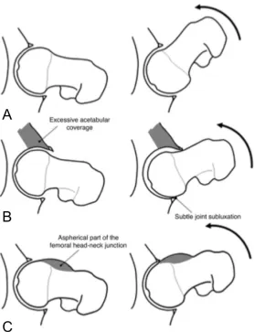
[20, 24, 25, 30]. This excessive acetabular coverage is characterized by the femoral head sitting in a deep socket of the pelvis, such as coxa profunda and protrusio acetabulum [31]. Coxa profunda is a condition in which the most medial aspect of the acetabular fossa is touching or overlapping the ilioischial line and protrusio acetabulum is a
Figure 2.2 - FAI pathology during flexion in a coronal view of the hip. (A) Normal hip joint clearance and movement during flexion. (B) Pincer impingement limits ROM and results in the acetabular rim impacting against the femur and causes subtle joint subluxation, which can cause a posteroinferior contre-coup injury. (C) The head-neck protuberance of cam impingement rotates into the acetabulum causing compression and shear forces of the anterosuperior acetabulum and limits ROM. Reprinted with permission from the American Journal of Roentgenology [33].
Phillippon et al. [37] studied 301 patients (153 males) who were undergoing surgery for FAI and only 50 patients were treated for pincer impingement, whereas 100 patients were treated for cam impingement and the majority, 151 patients, were treated for both cam and pincer impingement. Both patterns of labral and chondral damage are evident in individuals with mixed cam-pincer impingement [20].
2.4.2
Possible Causes of Femoroacetabular Impingement
Patients who present with FAI usually lack a clear history of hip disease. It has been suggested that the morphological variations may be caused by subtle developmental abnormalities such as Legg-Calvé Perthes disease and slipped capital femoral epiphysis for cam impingement and coxa profunda, acetabular retroversion, protrusio acetabuli, coxa vara, and os acetabuli for pincer impingement [20, 27, 29]. However, most cases are idiopathic [27].
2.4.3
Association of Osteoarthritis with Femoroacetabular
Impingement
[36] analyzed magnetic resonance arthrogram (MRA) findings in 50 patients (30 male) with FAI and found that 94% presented with anterosuperior labral lesions and that 84% had anterosuperior cartilage lesions. In agreement, Kassarjian et al. [34] evaluated MRA findings of 40 patients (22 male) with FAI and found that 100% of the patients had an anterosuperior labral tear and 95% displayed anterosuperior cartilage abnormalities. Labral lesions predispose the adjacent cartilage to degeneration. Cartilage degeneration then leads to bone exposure, which will ultimately lead to the development of OA [20, 39, 40]. Thus, FAI is a potential mechanism for the development of OA [20, 37, 40].
2.5 Diagnostic Measurement
2.5.1
Diagnostic Measurement for Hip Instability
Plain radiographs are typically the first tool used for the detection of acetabular dysplasia [41]. The centre-edge (CE) angle [21] and the vertical-centre-anterior (VCA) angle [21, 42] allow quantification of acetabular coverage. The CE angle, originally described by Wiberg [19], indirectly assesses the superolateral coverage of the acetabulum over the femoral head (Fig. 2.3) [43]. It is measured via two lines drawn from the centre of the femoral head on a centre cut coronal view of a magnetic resonance image (MRI) or an anteroposterior (AP) radiograph [21, 44]. One is a vertical line drawn from the centre of the femoral head through the acetabulum and the second is drawn from the centre of the femoral head through the lateral margin of the acetabulum. The angle formed between these lines is the CE angle [43]. A normal acetabulum is defined by a CE angle of greater than 25 degrees. A small CE angle is used to diagnose acetabular dysplasia (CE < 20°)
most anterior point of the acetabulum. The angle formed between these two lines represents the VCA angle. A VCA of >25° is considered to be normal, while a VCA
<25° is associated with acetabular dysplasia [21, 42].
Due to the continuing development of three-dimensional (3D) imaging technologies, 3D assessment of the hip joint is an emerging area of interest for detecting acetabular pathologies [41]. However, 3D measurements are often linear, similar to the plain radiograph measures, using computed-tomography (CT) slices and do not necessarily utilize the inherent 3D capabilities of CT data sets [21, 41, 45]. In contrast, Nakamura et al. [46] introduced a “top view of the hip” using 3D reconstructed models from CT scans to evaluate posterolateral acetabular deficiency. However, no one has used 3D
reconstructions to evaluate the surface morphology of the proximal femur and the acetabulum to better describe the entire surface morphology of the hip.
Figure 2.3 - Centre-edge (CE) angle, as described by Wiberg [19], is measured on a centre cut coronal MRI. A vertical line is drawn perpendicular to the horizontal line (C1, C2) from the centre of the femoral head. A second line is drawn from the centre of the femoral head to the most lateral point of the acetabulum (E). A normal
acetabular dysplasia [21]. Springer and Skeletal Radiology, 26 (2), 1997: p. 76, Radiographic Measurements of Dysplastic Adult Hips, S. Delaunay, Figure 1, is given to the publication in which the material was originally published; with kind permission from Springer Science and Business Media.
Figure 2.4 - Vertical-centre-anterior (VCA) angle, as established by Lequesne [42], is assessed on a false-profile view radiograph. V = Vertical; C = Centre; A =
Anterior. Normal VCA angles are >25°, while dysplastic VCA angles are <25° [21].
Springer and Skeletal Radiology, 26 (2), 1997: p. 77, Radiographic Measurements of Dysplastic Adult Hips, S. Delaunay, Figure 5, is given to the publication in which the material was originally published; with kind permission from Springer Science and Business Media.
2.5.2
Diagnostic Measurement for Femoroacetabular Impingement
of the femoral head exceeds the radius of the head [40]. There is no consensus of which alpha angle value is of diagnostic value for a hip with impingement.
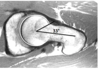
Figure 2.5 - Alpha angle. A normal alpha angle measurement on an MR image of a 25-year-old male. As established by Notzli et al. [40], it is established on a centre cut axial oblique MRI. The alpha angle is measured between two lines. The first line is drawn from the centre of the femoral head through the centre of the long axis of the femoral neck. The second line is drawn from the femoral head to the point where the contour of the femoral neck exceeds the radius of the femoral head. Normal alpha angles range from 33 to 48 degrees. Reprinted from authors MSc dissertation. Raynor, CM. 2008. Presence of markers of femoroacetabular impingement in the asymptomatic population. London: The University of Western Ontario. 88p.
The CE angle discussed previously can also be used to assess acetabular overcoverage as well as insufficient coverage. A normal acetabulum is defined by a CE angle of greater
than 25 degrees. A small CE angle is used to diagnose acetabular dysplasia (CE < 20°)
2.5.3
Reliability of Measures
Early detection and treatment of hip instability and FAI may help prevent the progression of OA; however, the current radiographic parameters for diagnosing these conditions are unreliable. For instance Clohisy et al. [18], evaluated the reliability of six hip specialists identifying important radiographic features of the hip on plain radiographs. The readers identified: acetabular version, inclination and depth, position of femoral head center, head sphericity, head-neck offset, Tönnis grade, and joint congruency and were asked to make a diagnosis of normal, dysplastic, FAI or combined dysplastic and FAI on two separate occasions. The Clohisy group concluded that the standard radiographic parameters used to diagnose dysplasia and FAI are not reproducible [18]. Additionally, the same group, Carlisle et al. [47], further investigated the reliability of radiographic measurements of the hip by various musculoskeletal physicians. They found that while the measurements were reliable for a given observer, the measurements were less reliable across observers and were limited in determining a consistent radiographic diagnosis. A clear set of definitions and measurements must be developed to enable more reliable diagnosis of early hip disease [18].
2.5.4
Challenges with Current Measures
3D technologies inherent in CT and MR data allows for visualization and quantification of the complete surface morphology of the hip.
2.6 Treatment
2.6.1
Treatment of Hip Instability
Conservative, non-surgical, management of hip instability consists of protected weight bearing and physical therapy. In more severe cases of hip instability surgical intervention is often recommended. The type of surgical intervention is determined by the underlying pathology associated with the instability. Surgical treatments may consist of open
reduction and internal fixation of a fracture, open or arthroscopic labral repair, osteoplasty, capsulorrhaphy, or osteotomy.
2.6.2
Treatment of Femoroacetabular Impingement
Orthopedic surgeons lack a consensus regarding the appropriate treatment of FAI. The classic radiographic findings for FAI consist of bony proliferation at the femoral head-neck junction, ossicle formation at the acetabular rim, labral tears, and cartilage flaps. Typically, orthopedic surgeons fall into three cohorts concerning the appropriate
lesions and removal of any loose bodies. Patients who receive this treatment are expected to experience short-term relief of symptoms, to notice a functional improvement, and to have a quick postoperative recovery. The third cohort of surgeons believes that
degenerative disease of the hip cannot be prevented or delayed and suggest conservative treatment and eventual total hip replacement [49].
2.7 3D Modelling
Since the advent of 3D imaging, CT and MRI, the use of 3D modelling for education, measurement, pre-operative assessment, and pre-surgical planning has become a supplement to traditional techniques [41, 50, 51]. 3D modelling allows optimal
noninvasive visualization of complex anatomical structures [52] and may afford new and more precise measurement possibilities.
Educational anatomical software has become increasingly available within the last decade. Programs have been developed for all levels of training, from the general public to medical professionals [53]. These programs have typically been in the form of an electronic book, presented with static anatomical images often enriched with animations and testing questions [53]. In contrast, 3D atlases offer the advantage of multiple views, interactivity, and visualization of real anatomical structures that are otherwise difficult to see [53].
The data sets acquired from 3D imaging can provide a 3D reconstruction of patient anatomy allowing personal and accurate measurement. This is an improvement from the standard 2D slice view and different colours can be allocated to different structures to replace the grey spectrum in the standard images [54].
Traditionally, clinical measurements for diagnoses have been based on plain radiographs, which are 2D measurements taken on a 2D scan. Quantifying 3D geometry on 2D planes with linear measurements does not accurately account for the entire joint morphology [48, 55]. Traditional 2D imaging techniques are evolving into 3D volume acquisitions with isotropic voxel sizes [56]. The increasing prevalence of 3D imaging has enabled 3D assessment of anatomical structures to become an area of interest [41].
2.7.2
3D Modelling in Education
Transfer of knowledge is very important in regards to anatomy and medicine. Historically the fundamental teaching tool for anatomical education was dissection [50, 57].
Dissection is still commonly used as an educational teaching tool; however, the hours allotted for anatomical education in the medical curriculum are drastically decreasing [58]. In order to compensate for this decrease in teaching time anatomical instructors are implementing other teaching methodologies such as 3D computer models [50].
Anatomical models have been used to assist anatomical learning for over a thousand years. However, more recent advances in technology have offered the ability to create visually rich and interactive 3D models [59]. Computer generated anatomy tools enable learners to work through self-directed learning modules at their own pace and the 3D models can often help learners conceptualize structures that are difficult to visualize in the gross anatomy lab [59].
include interactive capabilities for student reference [53]. 3D modelling has also been used in virtual simulation programs for surgical residents. These simulators allow surgeons to gain surgical proficiency without risking the lives of patients [60]. In
addition, using the same 3D technologies and measurements in education that are used in medicine helps with transferring knowledge from clinical practice to learner.
2.8 Why is a Comparison Needed?
3D virtual reconstructions have advantages over other types of imaging and modelling. Virtual reconstructions are not only visual representations of anatomical structures, these structures can be manipulated and dissected electronically, they can be measured and analyzed accurately, and the information can be stored, duplicated, and transferred among various computer platforms [52, 61]. If desired, stereolithography allows 3D
reconstructions to be outputted as physical models [61]. Due to the decreased cost and the increased speed and features of computers a variety of 3D reconstructive software
programs have been developed for scientific and educational use; however, no program has become the standard and the programs available differ in concept (voxel- or
polymesh-based), operating system, features, and cost [52, 61]. Landes, et al. [52] conducted a comparison of two software programs, SeViSe and SURFdriver, that
produced 3D reconstructions of histological slides. However, this study only outlined the differences between each program while conducting tasks, as opposed to utilizing a detailed evaluation form. Guyomarc’h et al. [62], conducted a comparative study between two software programs, Amira and Treatment and Increased Vision for Medical Imaging (TIVMI), investigating the measurement uncertainty created during data acquisition and surface reconstruction. They found that the 3D surface reconstruction created in TIVMI had higher precision and reproducibility than the reconstruction created in Amira;
however, this study did not look at the other features, advantages, or disadvantages of the programs. Lastly Matsumoto et al. [63], compared the characteristics, advantages,
programs, OsiriX, CTTRY, and Advantage Workstation Volume Share 4 (AW). They found that there were no notable differences in the vascular models at the segmental level and that all three programs were a useful reference during surgery [63]. However, AW is a program that is part of a General Electronic workstation that costs over 1.2 million Canadian dollars; thus, access to the AW software program is limited and not widely available for all research and educational purposes. Whereas the other two programs used are freeware. Furthermore, CTTRY is typically not used for medical imaging and is widely used for 3D movies and other applications. Thus it appears that, no study has been completed which evaluates the features of widely available medical imaging programs for usability, quality of model, and time efficiency.
2.9 3D Reconstructive Software Programs
Amira, Osirix, and Mimics are three programs that are widely available, cost effective, and are commonly used for anatomical research and educational purposes.
2.9.1
Amira
Amira (Mercury Computer Systems Inc., Chelmsford, USA) generates accurate reconstructions of anatomical structures automatically, semi-automatically, or by manually identifying regions of interest from serial sections. Anatomical models produced in Amira are capable of dynamic interaction and stereoscopic projection [64].

![Figure 2.3 - Centre-edge (CE) angle, as described by Wiberg [19], is measured on a centre cut coronal MRI](https://thumb-us.123doks.com/thumbv2/123dok_us/7784152.1287074/41.612.140.329.380.613/figure-centre-angle-described-wiberg-measured-centre-coronal.webp)