Mitigation of Voltage SAG Problem Using
Dynamic Voltage Restorer (DVR)
Saurabh Sahu
1, Neelesh Kumar
2M.Tech Scholar, Dept. of EEE, Disha Institute of Management & Technology, Raipur, C.G., India1
Assistant Professor, Dept. of EEE, Disha Institute of Management & Technology, Raipur, C.G., India2
ABSTRACT: The power quality (PQ) requirement is one of the most important issues for power system. The main problems of the power quality like voltage sags/swells in low voltage distribution systems and on the transmission side due to sensitive loads. There are different methods to compensation of voltage sag and swell, one of the most popular methods of sag and swell compensation is Dynamic Voltage Restorer (DVR), The Dynamic Voltage Restorer (DVR) is series-connected power electronics based device. It provides advanced and economic solution to compensate voltage sag and swell. This device can be implemented to protect a group of medium or low voltage consumers. This study presents compensation of sags and swells voltage during single line to ground (SLG) and three-phase faults. Simulation results carried out by Matlab/Simulink verify the performance of the proposed method.
KEYWORDS: power quality, Dynamic Voltage Restorer, single line to ground, Voltage Source Converter, Windowed Fast Fourier Transform.
I.INTRODUCTION
Dynamic Voltage Restorer (DVR) can provide the most cost effective solution to mitigate voltage sags and swells by establishing the proper voltage quality level that is required by customer. When a fault happens in a distribution network, sudden voltage sag will appear on adjacent loads. DVR installed on a sensitive load, restores the line voltage to its nominal value within the response time of a few milliseconds thus avoiding any power disruption to the load. There are many different methods to mitigate voltage sags and swells, but the use of a DVR is considered to be the most cost efficient method. The most common choice for the control of the DVR is the PI Controller since it has a simple structure and It can offer relatively a satisfactory performance over a wide range of operation. The main problem of this simple controller is the correct choice of the PI gains and the fact that by using fixed gains, the controller may not provide the required control performance, when there are variations in the system parameters and operating conditions. Various control strategies have been developed to mitigate the voltage sag and swell have been proposed for three phase voltage source PWM converters. They can be divided into two main groups: linear and non- linear, linear controllers include the ramp-comparison current regulator, Synchronous PI regulator, state feedback regulator and predictive and dead-beat regulator. The hard-switched converter and the neural network and Fuzzy Logic (FL) based regulators belong to the non-linear controllers. It appears that the non-linear controller is more suitable than the linear type since the DVR is truly a non-linear system. The DVR is a non-linear device due to the presence of power semiconductor switches in the inverter bridge. This paper introduces Dynamic Voltage Restorer (DVR) and its operating principle, also presents the proposed controllers of PI and fuzzy controllers. Then, simulation results using MATLAB-SIMULINK provide a comparison between the proposed and the conventional PI controllers in terms of performance in voltage sag/swell compensation at the end, discussions of the results and conclusion are given.
Literature Review
Haluk GOZDE and M.Cengiz[28]Proposed an artificial intelligence basedoptimization method is applied to optimize the gains ofPID controller for Automatic Voltage Regulator (AVR)system. A dynamic performance of the controller whichis optimized with Chaotic Particle Swarm Optimization(CPSO) algorithm is compared with the results whichare obtained with standard Particle SwarmOptimization (PSO). The transient response analysis isused in order to determine the performances of themethods.
Ali O Al-Mathnani, Hussain Shareef and AzahMohamed[29] proposed fast DVR with controller to compensate the short outage, reduced the harmonic distortion and transient voltage for balanced and unbalanced load. In-phase method with continues two vector controlalgorithm is used to detect and compensate ΔV and ΔQ variablesduring voltage sag and voltage compensation. When there is anyphase angle or phase jump in supply voltage the reference voltageis adjusted to track the phase angle of the supply voltage. A phaselocked loop is used to keep the load voltage synchronizedcontinuously and tracks the source voltage. It is shown that theproposed DVR controller improves the system power quality.Photovoltaic (PV) system with boost converter is designed tomaintain the DC source voltage. Simulation was carried out usingPSCAD/EMTDC.
II.REAL MODALOFDYNAMICVOLTAGERESTORER
Among the power quality problems voltage sags are the most severe disturbances. In order to overcome these problems the concept of custom power devices is introduced recently. One of those devices is the Dynamic Voltage Restorer (DVR), which is the most efficient and effective modern custom power device used in power distribution networks. DVR is a recently proposed series connected solid state device that injects voltage into the system in order to regulate the load side voltage. It is normally installed in a distribution system between the supply and the critical load feeder at the point of common coupling (PCC). Other than voltage sags and swells compensation, DVR can also added other features like: line voltage harmonics compensation, reduction of transients in voltage and fault current limitations[7,9].
A.DVR Basic Configuration and Components
Fig 1 shows the schematic diagram of DVR. It consists of an Injection transformer, Harmonic filter, Storage Devices, a Voltage Source Converter (VSC), and DC charging circuit and Control and Protection system
Fig 1 Schematic diagram of DVR
1. Energy Storage Unit
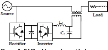
Figure 2. DVR with supply rectified energy
During voltage sag, the DVR injects a voltage to restore the load supply voltages. The DVR needs a source for this energy. Two types of system are considered; one using stored energy to supply the delivered power as shown in Figure 2, and the other having no internal energy storage, where energy is taken from the incoming supply through a shunt converter asShown in Figure 2.
The Voltage Source Inverter (VSI) or simply the inverter converts the dc voltage from the energy storage unit (or the dc link) to a controllable three phase ac voltage. The inverterSwitches are normally fired using a sinusoidal Pulse Width Modulation (PWM) scheme. Since the vast majority of voltage sags seen on utility systems are unbalanced, the VSI willOften operate with unbalanced switching functions for the three phases, and must therefore treat each phase independently. Moreover, sag on one phase may result in a swell on another phase, so the VSI must be capable of handling both sags and swells simultaneously. Another topology of the DVR is the use of multi-inverter system in cascade. This topology will add the voltage of the single cascaded inverters in series in order to obtain the desired inverter voltage. This method gets rid of the injection transformer used in the basic configuration of the DVR. This arrangement is often called a transformer-less or multilevel orA cascade inverter DVR [6-7].
3. Filter Unit
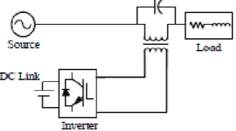
Figure 3. DVR with load side filter
The nonlinear characteristics of semiconductor devices cause distorted waveforms associated with high frequency harmonics at the inverter output. To overcome this problem and provide high quality energy supply, a harmonic filtering unit is used. These filters can be placed either in the inverter side as shown in Figure 2 or in the line side as shown in Figure 3.
4. Series Injection Transformer
Three single-phase injection transformers are used to inject the missing voltage to the system at the load bus. To integrate the injection transformer correctly into the DVR, the MVA rating,the primary winding voltage and current ratings, the turn-ratio and the short-circuit impedancevalues of transformers are required. The existence of the transformers allow for the design ofthe DVR in a lower voltage level, depending upon the stepping up ratio.
III.COMPENSATION METHODS IN DVR
The type of the compensation strategy mainly depends upon the limiting factors such as DVR power ratings, various conditions of load, voltage sag type. Some loads are sensitive towards phase angel jump and some are sensitive towards change in magnitude and others are tolerant to these [16]. Therefore, the control strategies depend upon the type of load characteristics; there are three different methods of DVR voltage injection which are:
(a) Pre-sag compensation method (b) In-phase compensation method
(c) Voltage tolerance method with minimum energy injection
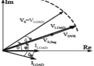
(a) Pre-Sag/Dip Compensation Method
Figure 4. Pre-Sag compensation
and amplitude. Sensitive loads would be achieved by pre-sag compensation method as shown in Figure 3. In this method the injected active power cannot be controlled and it is determined by external conditions such as the type of faults and load conditions. The voltage of DVR is given below:
VDVR = Vpre fault – Vsag
(b) In-Phase Compensation Method
In this method the injected voltage is in phase with the supply side voltage irrespective of the load current and pre-fault voltage as shown in Figure 5. The phase angles of the pre-sag and load voltage are different but the most important criteria for power quality that is the constant magnitude of load voltage are satisfied. The load voltage is given below: |VL| = |Vpre-fault| One of the advantages of this method is that the amplitude of DVR injection voltage is minimum for certain voltage sag in comparison with other strategies. Practical application of this method is in non-sensitive loads to phase angle jump.
Figure 5. In-phase Compensation (Magnitude compensation only)
(c) Voltage Tolerance Method with Minimum Energy Injection
Figure 6.Voltage Tolerance Method
The small voltage drop and phase angle jump on load can be tolerated by load itself. The sensitivity of loads to phase angle jump and voltage magnitude is different.
IV.SAG DETECTION TECHNIQUES
A voltage sag detection technique detects the occurrence of the sag, the start point, the end point, sag depth (magnitude to be restored) and phase shift. Common voltage sag detectionTechniques are summarized as follows [11-12]:
A. Peak value method
The simplest method of monitoring the supply is to monitor the peak, or amplitude, of the supply voltage, then comparing it with a reference. A controller could be set to recognize if there is a difference greater than a specified value (10%) and switch in the inverter.
B. Root Mean Square (rms) method
The start time of the sag can be defined as the first point of Vrms when drops below 0.9pu. To find the end time of the sag, search for an interval where Vrms drops below 0.9pu for at least half a cycle. The recovery time is then chosen as the first point in this interval.
C. Fourier Transform (FT)
The FT is achieved through orthogonal decomposition of power system signal. In general, a trigonometrically orthogonal function set or exponential orthogonal function set is utilized. By applying FT to each supply phase, it is possible to obtain the magnitude and phase of each of the frequency components of the supply waveform. For practical digital implementation Windowed Fast Fourier Transform (WFFT) is used, which can easily be implemented in real time control system. The only drawback of this method is that it takes one cycle to return the accurate information about the sag depth and its phase, since FT uses an averaging technique.
D. Space Vector method
The three phase voltages Vabc are transformed into a two dimension voltage Vdq, which in turn can be transferred into magnitude and angle. Any deviation in any quantity reveals the occurrence of an event. Comparing these quantities with reference ones will quantify the disturbance in the dq-frame, which had to be transformed back to the abc frame. This method has no time delay, yet requires complex controller.
ANN control method has adaptive and self-organization capacity. The ANN has inherent learning capability that can give improved precision by interpolation. FL controllers are an attractive choice when precise mathematical formulations are not possible. When a FL controller is used, the tracking error and transient overshoots of PWM can be considerably reduced. SVPWM control strategy is to adopt a space vector of the inverter voltage to get better performance of the exchange is gained in low switching frequency conditions.
V. CONTROL TECHNIQUES
A. Linear Controllers
The three main voltage controllers, which have been proposed in literature, are feed forward (open loop), Feedback (closed loop) and Multi-loop controller [13-18].The feed-forward voltage controller is the primary choice for the DVR, because of its simplicity and fastness. The supply voltage is continuously monitored and compared with a reference voltage; if the difference exceeds a certain tolerance, the DVR injects the required voltage. The drawback of the open loop controller is the high steady state error.In the feedback control, the load voltage is measured and compared with the reference voltage; the missing voltage is supplied by the DVR at the supply bus in a feedback loop. This controller has the advantage of accurate response, but it is complex and time-delayed. Multi-loop control is used with an outer voltage loop to Control the DVR voltage and an inner loop to control the load current. This method has the strengths of feed-forward and feedback control strategies, on the expense of complexity and time delay.
B. Non-linear Controllers
It appears that the nonlinear controller is more suitable than the linear type since the DVR is truly a non-linear system due to the presence of power semiconductor switches in the inverter bridge. The most non-linear controllers are the Artificial Neural Networks (ANN), Fuzzy Logic (FL) and Space Vector Pulse Width Modulation (SVPWM) [19-24]. ANN control method has adaptive and self-organization capacity. The ANN has inherent learning capability that can give improved precision by interpolation. FL controllers are an attractive choice when precise mathematical formulations are not possible. When a FL controller is used, the tracking error and transient overshoots of PWM can be considerably reduced. SVPWM control strategy is to adopt a space vector of the inverter voltage to get better performance of the exchange is gained in low switching frequency conditions.
VI.RESULT AND DISCUSSION
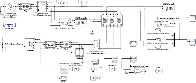
In order to show the performance of the DVR in voltage sags mitigation, a simple radial distribution network is simulated using MATLAB/SIMULNK. and shown in fig 7. The parameters of the main components are listed in the Table
A Three-phase l5 kV, 50Hz programmable voltage source is connected to a feeder and it is step down to 415V, 50 Hz through l5kV/415V transformer at Point of Common Coupling (PCC).
The DVR is connected in series between PCC and the nonlinear load with the help of an injection transformer .The primary side of injection transformer is connected in series with the load and secondary side is connected in delta to the DVR.A three phase fault is applied to the system in order to see the voltage sag. The DVR uses self-commutating IGBTsolid-state power electronic switches to mitigate voltage sags in the system. The voltage controlled three single-phase full bridges PWM inverters are used to produce compensating voltage. These inverters are connected to the common DC voltage source. The DC voltage source is an external source of supplying DC voltage to the inverter for AC voltage generation.
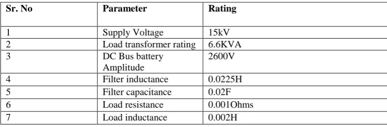
Table-I
TEST SYSTEM PARAMETERS
The basic function of the DVR is to inject a dynamically controlled voltage into the bus voltage by means of an voltage injection transformer. The momentary amplitudes of the three injected phase voltages are controlled such as to eliminate any detrimental effects of a bus fault to the load voltage VL. This means that any differential voltages caused by disturbances in the ac feeder will be compensated by an equivalent voltage. The DVR works independently to any of the type of fault or any event that happens in the system
Highly inductive load are applied to the test system to analyse the performance of DVR. Such faults are applied to the system during 50-150ms. Due to this voltage sag will occur.
Fig 5.1(a) shows the load voltage without DVR when a highly inductive load is applied and it is observed that 85% Voltage sag is initiated at 0.05s and it is kept until 0.15s, with total voltage sag duration of0.1s. Fig 5.1(b) shows the RMS Voltage without DVR. Due to the condition.
Fig5.1 (a) Load voltage without DVR
Sr. No Parameter Rating
1 Supply Voltage 15kV
2 Load transformer rating 6.6KVA
3 DC Bus battery
Amplitude
2600V
4 Filter inductance 0.0225H
5 Filter capacitance 0.02F
6 Load resistance 0.001Ohms
0 0.05 0.1 0.15 0.2 0.25 0.3 0.35 0.4 0.45 0.5 0
2000 4000 6000 8000 10000 12000 14000
Magnitude of 3-Phase supply with SAG
TIME
VOLTAGE PU
Fig 5.1(b) RMS Voltage without DVR.
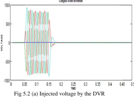
Now DVR with the proposed controls scheme is connected to the system. Fig 5.2 (a) shows the injected voltage by the DVR with PI controller during 0.2ms to 0.25ms to the system with the help of injection transformer in order to maintain the load voltage constant.
Fig 5.2 (a) Injected voltage by the DVR
The amplitude index is kept fixed at 1pu, in order to obtain the highest fundamental voltage component at the controller output.
k =VControl VTrin
= 1 pu
VControlis the peak amplitude of the control signal
VTrinis the peak amplitude of the triangular signal
The switching frequency is set at 1035Hz. The frequency modulation index is given by,
mf =
fs
f1
=1035
50 = 20.7
Where f1 is the fundamental frequency?
Fig 5.3 Pulses generated by Discrete PWM Generator..
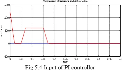
Fig 5.4 Input of PI controller
Fig 5.4(a) shows the load Voltage after compensation with PI controller... Here the load voltage is 98% of the supply voltage. Fig 5.4(b) shows the load RMS Voltage after compensation using PI controller. Here RMS voltage is maintained to 98% at the sensitive load point. From the below figures it is concluded that using PI controller performance of DVR is more satisfactory then the conventional method
Fig 5.4(a) Load Voltage after compensation with DVR. 0 0.05 0.1 0.15 0.2 0.25 0.3 0.35 0.4 0.45 0.5 -5000
0 5000 10000 15000
Comperision of Refrence and Actual Value
TIME
Fig 5.4(a) RMS Voltage after compensation with DVR.
VII.CONCLUSION
In this paper the main objectives for the utilization of the studied equipment to mitigate the voltage sag. In order to protect critical loads from more sever fault in distribution network. The facility available in MATLAB/SIMULINK is used to carry out extensive simulation study. Supply voltage is compared with reference voltage to get error signal which is given to the gate pulse generation circuit as a reference sine wave which is compared with carrier signal to get pulses for inverter. Voltage sag values are major factors in estimating the DC storage value. The effectiveness of a DVR system mainly depends upon the rating of DC storage rating and the percentage voltage sag. In the test system it is observed that after a particular amount of voltage sag, the voltage level at the load terminal decreases.
REFERENCES
[1] A. Visser, J. Enslin and H. Mouton, "Transformer-less Series Sag Compensation With a Cascaded Multilevel Inverter", IEEE Trans. Industrial
Electronics, Vol. 49(4), Aug. 2002, pp. 824-831.
[2] P. Loh, M. Vilathgamuwa, S. Tang and H. Long, "Multilevel Dynamic Voltage Restorer", IEEE Power Electronics Letters, Vol. 2(4), Dec. 2004, pp. 125-130.
[3] S. Choi, J. Li and M. Vilathgamuwa, "A Generalized Voltage Compensation Strategy for Mitigating the Impacts of Voltage Sags/Swells",
IEEE Trans. Power Delivery, Vol. 20(3), July 2005, pp. 2289-2298.
[4] C. Meyer, C. Romaus and R. De Doncker, "Optimized Control Strategy for a Medium- Voltage DVR", IEEE Trans. Power Electronics, Vol. 23(6), Nov. 2008, pp. 2746-2754.
[5] Q. Wang and S. Choi, "An Energy-Saving Series Compensation Strategy Subject to Injected Voltage and Input-Power Limits", IEEE Trans.
Power Delivery, Vol. 23(2), Apr. 2008, pp. 1121-1131.
[6] C. Fitzer, M. Barnes and P. Green, "Voltage Sag Detection Technique for a Dynamic Voltage Restorer", IEEE Trans. Industry Applications,
Vol. 40(1), Jan. 2004, pp. 203212.B. Bae, J. Jeong, J. Lee and B. Han, "Novel Sag Detection Method for Line-Interactive Dynamic Voltage Restorer", IEEE Trans. Power Delivery, Vol. 25(2), Apr. 2010, pp. 1210-1211.
[7] J. Nielsen, M. Newman, H. Nielsen and F. Blaabjerg, "Control and Testing of a Dynamic Voltage Restorer (DVR) at Medium Voltage Level",
IEEE Trans. Power Electronics, Vol. 19(3), May 2004, pp. 806-813.
[8] H. Kim and S. Sul, "Compensation Voltage Control in Dynamic Voltage Restorers by Use of Feed Forward and State Feedback Scheme",
IEEE Trans. Power Electronics, Vol. 20(5), Sep. 2005, pp. 1169-1177.
[9] M. Marei, E. El-Saadany and M. Salama, "A New Approach to Control DVR Based on Symmetrica Components Estimation", IEEE Trans.
Power Delivery, Vol. 22(4), Oct. 2007, pp. 2017-2024.
[10] M. Bongiorno, J. Svensson and A. Sannino, "An Advanced Cascade Controller for Series- Connected [11] VSC for Voltage Dip Mitigation", IEEE Trans. Industry Applications, Vol. 44(1), Jan. 2008, pp. 187-195.
[12] O. Abdelkhalek, A. Kechich, T. Benslimane, C. Benachaiba and M. Haidas, "More Stability and Robustness with the Multi-loop Control Solution for Dynamic Voltage Restorer", Serbian Journal of Electrical Engineering, Vol. 6(1), May 2009, pp. 75-88.
[13] H. P. Tiwari, S. K. Gupta, "Dynamic Voltage Restorer Based on Load Condition", International Journal of Innovation, Management and
Technology, Vol. 1(1), April 2010, pp. 75-81.
[14] S. Ganesh, K. Reddy and B. Ram, "A Neuro Control Strategy for Cascaded Multilevel Inverter Based Dynamic Voltage Restorer",
International Journal of Electrical and Power Engineering, Vol. 3(4), 2009, pp. 208-214.
[15] P. Margo, M. Heri, M. Ashari, M. Hendrik and T. Hiyama, "Compensation of Balanced and Unbalanced Voltage Sags using Dynamic Voltage Restorer Based on Fuzzy Polar Controller", International Journal of Applied Engineering Research, Vol. 3(3), 2008, pp. 879-890.
[16] H. Ezoji, A. Sheikholeslami, M. Rezanezhad and H. Livani, "A new control method for Dynamic Voltage Restorer with asymmetrical inverter legs based on fuzzy logic controller", Simulation Modelling Practice and Theory, Vol. 18, 2010, pp. 806-819.
[17] C. Zhan, V. Ramachandaramurthy, A. Arulampalam, C. Fitzer, S. Kromlidis, M. Barnes and N. Jenkins, "Dynamic Voltage Restorer Based on Voltage-Space-Vector PWM Control", IEEE Trans. Industry Applications, Vol. 37(6), Nov. 2001, pp. 1855-1863.
[18] H. Ding, S. Shuangyan, D. Xianzhong and J. Jun, "A Novel Dynamic Voltage Restorer and its Unbalanced Control Strategy Based on Space Vector PWM", Electric Power and Energy Systems, Vol. 24, 2002, pp. 693-699.
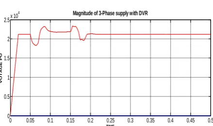
0 0.05 0.1 0.15 0.2 0.25 0.3 0.35 0.4 0.45 0.5
0 0.5 1 1.5 2 2.5x 10
4 Magnitude of 3-Phase supply with DVR
TIME
VO
TAG
E P
[19] N. H. Woodley, L. Morgan, and A. Sundaram, “Experience with an inverter-base dynamic voltage restorer,” IEEE Trans. Power Delivery, vol. 14, pp. 1181–1185, July 1999. N. H. Woodley, A. Sundaram, B. Coulter, and D. Morris, “Dynamic voltage restorer demonstration project experience,” in Proc. 12th Conf. Elect. Power Supply Ind., Pattaya, Thailand, 1998.
[20] F. Z. Peng, H. Akagi, and A. Nabae, “Compensation characteristics of the combined system of shunt passive and series active filters,” IEEE Trans. Ind. Applicat., vol. 29, pp. 144–151, Jan./Feb. 1993.
[21] H. Fujita and H. Akagi, “The unified power quality conditioner: The integration of series- and shunt-active filters,” IEEE Trans. Power Electron., vol. 13, pp. 315–322, Mar. 1998.
[22] A. Campos, G. Joos, P. D. Ziogas, and J. F. Lindsay, “Analysis and design of a series voltage unbalance compensator based on a three-phase VSI operating with unbalanced switching functions,” IEEE Trans. Power Electron., vol. 9, pp. 269–274, May 1994.
[23] ArindamGhosh, and Gerard Ledwich”Compensation of Distribution System
[24] Voltage Using DVR”, IEEE Transactions on Power Delivery, Vol. 17, No. 4, October 2002
[25] Choi, S.S.; Li, B.H.; Vilathgamuwa, D.M.; “Design and analysis of the inverter-side filter used in the dynamic voltage restorer”, IEEE Transactions onPower Delivery, Volume: 17, Issue: 3, July 2002 Pages: 857 – 864.
[26] Fitzer, C.; Barnes, M.; Green, P.; “Voltage sag detection technique for a dynamic voltage restorer” Industry Applications, IEEE Transactions on, Volume: 40, Issue: 1, Jan.-Feb. 2004.
[27] Prakash, Y.;Sankar, S.; “Power Quality Improvement Using DVR in Power System” Power and Energy Systems: Towards Sustainable Energy (PESTSE 2014)
[28] Haluk GOZDE, M.Cengiz TAPLAMACIOĞLU “Automatic Voltage Regulator (AVR) Design with Chaotic Particle Swarm Optimization”ECAI 2014 - International Conference – 6th Edition Electronics, Computers and Artificial Intelligence 23 October -25 October, 2014, Bucharest, ROMÂNIA