Design Of Acoustical Bessel-Like Beam Formation By
Tunable Angular Spectrum In Soret Zone Plate Lens
Daniel Tarrazó-Serrano1 , Sergio Castiñeira-Ibáñez1 , Oleg V. Minin2, Pilar Candelas1, Constanza Rubio1,∗ and Igor V. Minin3,∗
1 Centro de Tecnologías Físicas, Universitat Politècnica de València, Camí de Vera s/n, 46022 València, Spain;
[email protected] (D.T.-S.), [email protected] (S.C.-I.), [email protected] (P.C.), [email protected] (C.R.)
2 Tomsk State University, 30 Lenin Avenue, Tomsk, 634050, Russia; [email protected]
3 Tomsk Politechnical University, 36 Lenin Avenue, Tomsk, 634050, Russia; [email protected]
* Correspondence: [email protected]; [email protected]
Academic Editor: name
Version September 11, 2018 submitted to Preprints
Abstract:The image performance of acoustic and ultrasound sensors depends on several fundamental 1
parameters such as depth of focus or spatial resolution. There are currently two different type 2
of acoustic diffractive lenses: those which form a diffraction-limited spot with a shallow depth 3
of focus (zone plates) and lenses which form an extended focus (quasi-Bessel beams). In this 4
paper, we investigate a pupil-masked Soret zone plate which allows the tunability of a normalized 5
angular spectrum. It is shown that the depth of focus and the spatial resolution can be modified, 6
without changing the lens structure, by choosing the size of the amplitude pupil mask. This effect 7
is based on the transformation of spherically converging waves into quasi-conical waves, due to 8
the apodization of the central part of the zone plate. The theoretical analysis is verified with both 9
numerical simulations and experimental measurements. A Soret zone plate immersed in water 10
with D/2F=2.5 and F=4.5λ, changes its depth of focus from 2.84λto 5.9λand the spatial resolution
11
increases from 0.81λto 0.64λat a frequency of 250 kHz, by modifying the pupil mask dimensions of
12
the Soret zone plate. 13
Keywords:ultrasonic lens; apodization; Soret zone plate 14
1. Introduction 15
The necessity of manipulating waves has been one of the main objectives of the scientific 16
community. Lenses are devices that achieve, through different physical phenomena such as refraction 17
or diffraction, beam focusing and modulating effects. In the acoustic field, lenses have been developed 18
for different areas such as biomedicine, engineering, industry and those applications which require a 19
reduced cost of acoustic lenses [1–11]. 20
Due to the interest that these lenses arose, their design and improvement is currently a research 21
subject. One type of acoustic lenses are those which change the refractive index among the medium 22
known as Gradient-Index (GRIN) lenses using labyrinthine structures [12–14]. Phononic crystals [15], 23
acoustic metamaterials [16] and acoustic resonators [17] have also been used in the implementation of 24
acoustic lenses. 25
Fresnel Zone Plates (FZP), as a simple example of acoustic lens, have been used in this study due 26
to their dimension and fabrication advantages [18–20]. FZPs are constructed alternating opaque and 27
transparent acoustic rings and use the diffraction phenomenon to modulate and focus acoustic waves. 28
These classic FZPs are also called Soret Zone Plates (SZPs) [21]. 29
Calvoet al.developed and characterized a SZP for underwater ultrasounds, alternating opaque 30
and transparent zones made of soft silicone rubber [22]. Results shown a main lobe widening but 31
also, a small reduction of the first Side Lobe Level (SLL). A zone plate based on fractal structures was 32
studied in [23]. 33
Acoustic field diffraction produces a maximum pressure field located in the central axis, 34
nonetheless the secondary lobes produce miss-definition on the focal point [24–26]. SLL and Depth of 35
Focus (DoF) are one of the problems that SZP lenses have [27]. Although energy is concentrated at 36
the Focal Length (FL), SLL levels in SZP lenses are not sufficient if the target application requires high
37
precision. 38
This work is based on the study carried out by Mininet al.in the field of electromagnetism [28]. 39
In that study, a modification on the distribution of energy modification at the focus was proposed. 40
The authors showed that by choosing a radius or phase reference in the first SLL radii, the SLL ratio 41
was improved [29,30]. These results can be transferred to the ultrasonic field. Later the concept of the 42
reference radius was independently used in acoustics in [31], but without analyzing the image quality. 43
The quality of the image is determined by the beam distribution (lateral resolution,Rlat) and
44
axial resolution,Rax. For an arbitrary circular aperture at the focus, simplified expressions for lateral
45
resolution,Rlat, and (DoF), are [32]:
46
Rlat=αλF
D =αλf
# (1)
DoF=βλ
F D
2
=βλf#2 (2)
Here, the ratio of the focal length to the diameter is the f-number f#. From Equations (1) and (2) it
47
is followed that [33]: 48
DoF= β
α2λR
2
lat (3)
Equation (1) is valid also in the focal area for a focused lens with a high numerical aperture [34]. 49
One could see that depending on the choice of frequency andf#, the resolution can vary over several
50
orders of magnitude. 51
To increase the depth of focus and spatial resolution many papers investigated acoustic Bessel 52
beams due to the central core spot size of the Bessel beam, which is defined from the properties of the 53
zeros of a Bessel function and is given by: 54
Rlat=2.4048/kr (4)
wherekris a radial wave vector [35].
55
For example, a flat acoustic lens with an aperiodical structure to transform a divergent beam into 56
a Bessel like beam was reported in [36]. Bessel beams of sound waves were also reported in [37,38]. 57
However, they are not as broadly applied as in optics, which is perhaps related to the lack of convenient 58
techniques of formation of such kind of acoustic waves. Acoustic Bessel beams have been excited 59
using acoustical axicons [39], in analogy to the optical case. In any case, the most convenient way to 60
form acoustic Bessel beams is by using annular transducer arrays [40,41]. The acoustic Bessel-like 61
beam by means of an axisymmetric grating of rigid tori was reported in [42]. It could be mentioned 62
that if Babinet’s principle is considered, both approaches (FZP and rigid tori scatterers) are considered 63
equivalent. 64
The present work proposes and demonstrates a new technique for acoustic quasi-Bessel beam 65
formation using a planar structure based on SZPs [21]. Two concepts for a diffraction lens design are 66
considered: based on the reference phase method and the amplitude pupil mask. It can be affirmed 67
that, under specific conditions, part of a diffracted wave collimates producing an elongated focus. 68
Numerical calculations using Finite Element Method (FEM) of acoustic waves propagating through 69
such lenses were used to observe the complete acoustic field. Finally, the experimental verification of 70
2. Mathematical Method and Simulations 72
SZPs are based on ring sections known as Fresnel Regions. The purpose is to block the destructive 73
contributions to the focus. Therefore, consecutive Fresnel Regions have aπphase shift between zones.
74
SZP’s building parameters areFL, the Number of Fresnel Zones (N) and the working frequency (f).
75
The radii are obtained from the following Fresnel construction equation, 76
rn=
s nλFL+
nλ
2
(5)
The reference radius is defined arbitrarily, on account that the properties of the zone plate are 77
not modified from the point of view of geometrical optics [28]. Nevertheless, this reference radius is 78
equal to modify the reference phase in the wave approximation [30]. This phase shift introduces the 79
quasi-Fresnel radii concept. These radii are defined, for the plane incident wavefront, by the following 80
equation, 81
rn=
s
nλ
q F2
L+r20+
nλ
2 2
+r2
0 (6)
The study of the physical phenomena involved in the interaction between the lenses and the 82
wave front requires a mathematical model that considers the boundary conditions of the problem. 83
In the present work, the FEM method has been used through the commercial software COMSOL 84
Multiphysics [43] to calculate the acoustic pressure distribution. This method generates a numerical 85
solution by discretizing the model, solving Helmholtz’s Partial Differential Equation, 86
∇ ·
− 1
ρ0
(∇p)
= ω
2p
ρ0c2
(7)
One of the problems with the use of FEM, is the extensive usage of memory resources. To 87
avoid them, axisymmetric models have been considered. This design, simplifies the calculation when 88
considering that half-lens generates the rest of the model by turning 2π. Therefore, the degrees
89
of freedom needed to obtain the numerical solution are reduced, decreasing the computation time. 90
Underwater transmission is considered, and to solve Equation (7) typical water values of sound speed 91
propagation (c=1500m/s) and density (ρ=1000kg/m3) are taken. Design frequency (f) is 250 kHz,
92
therefore wavelength (λ) is 6 mm. Lenses were defined as full rigid considering Neumann condition
93
that specifies sound velocity in the boundary is zero. The exterior contours of the model emulate the 94
Sommerfeld condition. This boundary condition turns into an infinitely host defining these contours 95
as radiation boundaries. Mesh geometry was fixed in triangles with minimum element size ofλ/14
96
and maximum element size ofλ/8 to prevent numerical dispersion.
97
In the current paper, the lenses with high numerical aperture (N A) were selected (D/2F=2.5). 98
Focusing of this device (F=4.5λ) leads to a very compact beam with a short working distance. Below
99
it has been considered and compared three types of SZPs based on acoustic lenses: classical SZP, zone 100
plate with amplitude pupil mask (PSZP) and zone plate based on reference phase concept (RSZP). 101
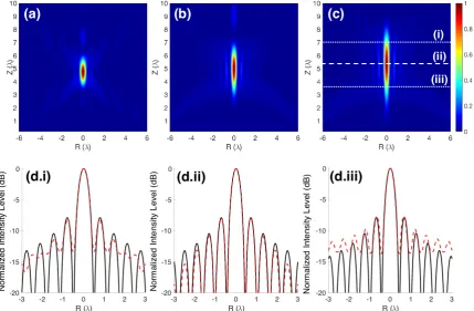
The simulation results are presented in self-normalized intensity maps with normalized axis to the 102
wavelength as shown in Figure1. Also, normalized intensity radial and longitudinal cuts along the R 103
and the Z axis are shown in Figure2, respectively. 104
From Figure1it is clear that the structures of focused acoustic fields in the focal area are different 105
and in the cases of PSZP and RSZP have an extended focus. Moreover, from Equation (5) and Equation 106
(6) it is followed that ifr0in Equation (6) equal tornfrom Equation (5), the Fresnel radii for classical
107
Equation (5) and Reference phase SZP Equation (6) are equal abover0. Thus, such PSZP and RSZP
108
will give equal results for the focal area formation. The focused field in the cases of PSZP and RSZP 109
has a characteristic structure for quasi-Bessel beams with intensity profiles that closely resemble the 110
Figure 2.Numerical normalized intensity results for (a) R axis cut and (b) Z axis cut. Black solid line corresponds to classical Soret Zone Plate (SZP), blue dotted line corresponds to Reference Radius Soret Zone Plate (RSZP) and dash-dotted red line corresponds to the amplitude pupil masked Soret Zone Plate (PSZP).
Table 1.FLHM and FWHM comparison between numerical and experimental results.
FLHM (λ) FWHM (λ)
SZP 2.84 0.81
RSZP 3.67 0.60
PSZP 5.94 0.64
BesselJ2
0 - 0.64
FZP13Z7 (Experimental SZP) 3.51 0.79 PM13Z4 (Experimental PSZP) 5.72 0.67
The normalized intensity distributions along optical axis are presented in Figure2. It can be 112
observed that a maximum normalized intensity value is obtained for the SZP case. Normalized 113
intensity values for RSZP and PSZP are 0.94 and 0.76, respectively. 114
As the central zones for PSZP are covered, the central peak sharpens further. However, the 115
relative side lobe intensity is increased. Thus, the central zones play an important role in reducing the 116
background, while the outer zones cause the central peak to be sharpen. The diameter of the central 117
maximum at the focal spot is less than the equivalent Airy disk, partly because the open areas are 118
smaller than the corresponding Fresnel zones (see Table1). In this Table it is compared the Full Length 119
Half Maximum (FLHM) and Full Width Half Maximum (FWHM) of each lens. FLHM is defined as the 120
distance along the longitudinal axis where the energy is reduced to the half. FWHM is equivalent to 121
the FLHM but considering the transversal axis. 122
Compared to a classical SZP, an acoustic PSZP has the following main characteristics. Focus 123
depth is larger than classical SZP; its resolution is better for point objects since the central maximum is 124
narrower and it has a little more energy in the outer rings of the diffraction pattern (compared to the 125
central maximum). 126
As it was mentioned above that PSZP and RSZP generate quasi-Bessel beams as shown in Figure 127
1. As for RSZP, in general, it can be mentioned that effectively, by increasing the diameter of the 128
amplitude pupil, the diameter of the central spot is reduced, and the depth of focus is increased with 129
the relative amplitude of the secondary lobes is increased. It is worth mentioning that in [32] a paraxial 130
study of this phenomenon in optics was made in contrast to our study made for acoustic lens with 131
highN A. 132
The effects of extended depth of focus with quasi-Bessel structure both for PSZP and RSZP may 133
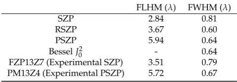
Figure 3.Beam formation scheme of (a) SZP and (b) PSZP.
The binary SZP lens consists of concentric dielectric ring, which can be treated as a quasi-periodic 135
grating with different local grating constants at different radii. For single-point focusing, the normal 136
incident wave is diffracted towards the designed focal point by these local gratings. The diffraction 137
angles has a large range of different radii to ensure the formation of a focal spot (Figure3a). The 138
normalized radial spatial frequencykr/kis related to the angleθaskr/k=sinθwherekris the radial
139
components of wave vectork, andθis the angle between the wave vector and optical axis. For an ideal
140
Bessel beam, the values ofkr, andθare the same for all plane waves consisting of the beam. The range
141
of the diffraction angle (θi) corresponds to the normalized angular spectrum bandwidth.
142
SZP with pupil masked central part and reference phase FZP with first reference radius equal to 143
pupil mask dimension may be also considered as circular gratings. Due to the widths of zones are 144
almost constant so PSZP and RSZP lenses are similar to ring diffraction grating. Thus the local gratings 145
diffract the incident waves towards different points on the optical axis with a small range of diffraction 146
angle (Figure3b). 147
The interference pattern is a 2D Bessel function of the first kind, located at the focal distance. 148
Therefore, the local grating constant d(r) at radius r can be obtained by the grating equation, 149
d(r)sinθ(r) =λ, whereλis the incident wavelength. Thus, the angular spectrum of the acoustic lens
150
based on the SZP is controlled by the selection of the pupil mask size. It could be noted that due to 151
acoustical lens is immersed in water the angular spectrum is compressed according to refractive index 152
of a medium. 153
Most of the focused wave is diffracted from the outer rings and the first-order diffraction beams 154
intercept the optical axis and form the acoustical needle, which is similar to the formation of a 155
quasi-non-diffracting beam with conical lenses. 156
It could be noted that in the optical band, the pupil mask method was used to block the light 157
through the central part in the point-focusing super-oscillatory lenses to achieve aDoFas long as 158
5λ-20λ. However, the realization of such an extendedDoFwas at the expense of degradation in the
159
focus transverse size [44,45]. 160
3. Experimental Results 161
In order to carry out the experimental measurements, the SZP and the PSZP have been 162
implemented in brass using a mechanization process. The material selected for its construction 163
is brass because it has a relatively low transmission coefficient and behaves as an opaque sound 164
material as shown in the Figure4. 165
All the measures have been done using an automated full precision measurement system in order 166
to validate and compare the proposed lenses. This well-know system consists in a fixed ultrasonic 167
transducer and a 3D positioned hydrophone [46]. This systems grants precise and reliable results with 168
1×1 mm2scanning. The transducer used is a 250 kHz Imasonic piston with 32 mm of active diameter
169
with a diameter of 1.5 mm. Flat transfer function between 0.2 and 15 MHz provides accuracy on the 171
measurements. 172
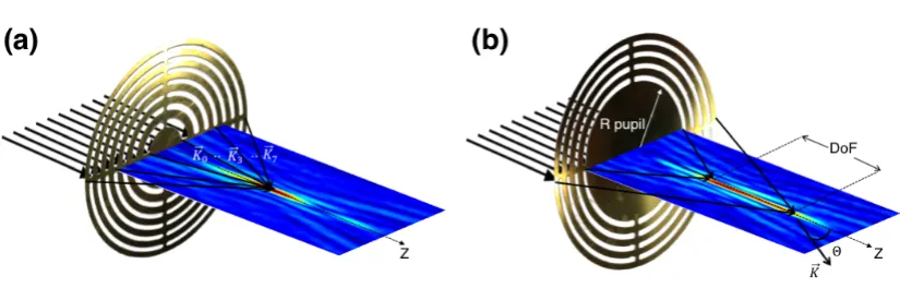
Figure 4. Implemented lenses in brass for experimental results. Where (a) corresponds to the experimental classical Soret Zone Plate (FZP13Z7) and (b) corresponds to the implemented amplitude Pupil Masked Soret Zone Plate (PM13Z4).
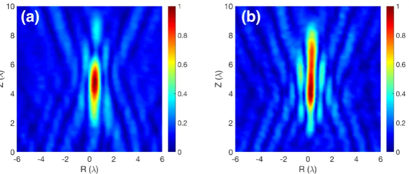
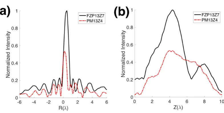
Figure5shows the experimental self-normalized intensity maps for Figure 5a implemented 173
SZP (FZP13Z7) and Figure5b implemented PSZP (PM13Z4). The axial and longitudinal normalized 174
intensity cuts are shown in Figure6. Figure6a corresponds to axial or R-axis cut and can be seen that 175
the consideration of a pupil generates a distribution of energy along the longitudinal axis narrowing 176
the beam and generating a quasi-Bessel beam distribution. Experimental results are in good agreement 177
with the presented numerical results. 178
Figure 6. Experimental normalized intensity results for both implemented lenses. Axial and longitudinal axis are shown, where (a) corresponds to R-axis cuts and (b) corresponds to Z-axis cuts.
4. Conclusion 179
In this work, we have proposed an improvement over a classical SZP introducing an amplitude 180
pupil mask. The idea of a normalized angular tunable acoustic spectrum has been verified. The design 181
of a quasi-non-diffracting beam with sub-wavelength transverse size is achieved using a pupil-masked 182
or reference phase SZP. This design has been verified using numerical models and the experimental 183
measurements in controlled conditions. When an amplitude pupil masked is used, a quasi-Bessel beam 184
instead of a diffraction spot focus is obtained. This effect is produced by modifying the spherically 185
converging waves into quasi-conical waves. Therefore, a quasi-Bessel beam distribution is obtained 186
when an amplitude pupil masked SZP is used. 187
With the amplitude pupil masked SZP proposed in this paper, a spatial resolution enhancement 188
from 0.81λto 0.64λis accomplished. In addition, depth of focus is increased from 2.84λto 5.94λ
189
compared with the classical SZP. The experimental results are in good agreement with the numerical 190
ones. The obtained results allows to modulate the acoustic beam without changing the lenses. 191
Therefore, the same SZP could be used for different targets by adding an amplitude pupil mask. 192
In consequence, these results confer great versatility to SZP lenses. This type of PSZP could have 193
applications in different areas where compromise betweenDoFand partial resolution is needed. As 194
happens in 3D imaging, ultrasonic sensors with long depth of focus eliminates the need for depth 195
scanning making this technique considerably faster. 196
Author Contributions:Igor V. Minin and Constanza Rubio coordinated the theoretical development, participating 197
in the establishment of the theory principles used in this work, as well as in the drafting of the manuscript. 198
Constanza Rubio and Daniel Tarrazó-Serrano coordinated experimental development. Oleg V. Minin and 199
Sergio Castiñeira-Ibáñez developed part of the theory used and designed some characterization. Pilar Candelas 200
participated in the analysis of the state of art, as well as the project administration and funding acquisition. 201
Acknowledgments:This work has been supported by Spanish MINECO (TEC2015-70939-R) and was partially 202
supported by Tomsk Polytechnic University Competitiveness Enhancement Program. 203
205
1. Pignoli, P.; Tremoli, E.; Poli, A.; Oreste, P.; Paoletti, R. Intimal plus medial thickness of the 206
arterial wall: A direct measurement with ultrasound imaging. Circulation 1986, 74, 1399–1406. 207
doi:10.1161/01.CIR.74.6.1399. 208
2. Amemiya, I.; Yagi, H.; Mori, K.; Yamamoto, N.; Saitoh, S.; Tanuma, C.; Hirahara, S. Ink Jet Printing with 209
Focused Ultrasonic Beams. Recent Progress in Ink Jet Technologies II; Vol. 5, Society for Imaging Science and 210
Technology, 1999; pp. 274–279. 211
3. McCann, D.; Forde, M. Review of NDT methods in the assessment of concrete and masonry structures. 212
NDT and E International2001,34. 213
4. Li, J.T.; Han, J.F.; Yang, J.H.; Li, T.S. An efficient synthesis of 3, 4-dihydropyrimidin-2-ones catalyzed by 214
NH2SO3H under ultrasound irradiation. Ultrasonics Sonochemistry2003,10, 119–122. 215
5. Albu, S.; Joyce, E.; Paniwnyk, L.; Lorimer, J.; Mason, T. Potential for the use of ultrasound in the 216
extraction of antioxidants from Rosmarinus officinalis for the food and pharmaceutical industry.Ultrasonics 217
Sonochemistry2004,11, 261–265. 218
6. Illing, R.; Kennedy, J.; Wu, F.; Ter Haar, G.; Protheroe, A.; Friend, P.; Gleeson, F.; Cranston, D.; Phillips, R.; 219
Middleton, M. The safety and feasibility of extracorporeal high-intensity focused ultrasound (HIFU) for 220
the treatment of liver and kidney tumours in a Western population.British journal of cancer2005,93, 890. 221
7. Vilkhu, K.; Mawson, R.; Simons, L.; Bates, D. Applications and opportunities for ultrasound assisted 222
extraction in the food industry—A review. Innovative Food Science & Emerging Technologies2008,9, 161–169. 223
8. Schonbrun, E.; Rinzler, C.; Crozier, K.B. Microfabricated water immersion zone plate optical tweezer. 224
Applied Physics Letters2008,92, 071112. 225
9. Hon, S.; Kwok, K.; Li, H.; Ng, H. Self-focused acoustic ejectors for viscous liquids. Review of scientific 226
instruments2010,81, 065102. 227
10. Calvo, D.C.; Thangawng, A.L.; Nicholas, M.; Layman, C.N. Thin Fresnel zone plate lenses for underwater 228
acoustics: Modeling and experiments. OCEANS’15 MTS/IEEE Washington2015. 229
11. Tu, Y.L.; Chen, S.J.; Hwang, Y.R. Design of Fresnel Lens-Type Multi-Trapping Acoustic Tweezers.Sensors 230
2016,16, 1973. 231
12. Welter, J.T.; Sathish, S.; Christensen, D.E.; Brodrick, P.G.; Heebl, J.D.; Cherry, M.R. Focusing of longitudinal 232
ultrasonic waves in air with an aperiodic flat lens. The Journal of the Acoustical Society of America2011, 233
130, 2789–2796. doi:10.1121/1.3640841. 234
13. Li, Y.; Liang, B.; Tao, X.; Zhu, X.F.; Zou, X.Y.; Cheng, J.C. Acoustic focusing by coiling up space. Applied 235
Physics Letters2012,101. 236
14. Peng, P.; Xiao, B.; Wu, Y. Flat acoustic lens by acoustic grating with curled slits.Physics Letters, Section A: 237
General, Atomic and Solid State Physics2014,378, 3389–3392. doi:10.1016/j.physleta.2014.09.042. 238
15. Cervera, F.; Sanchis, L.; Sánchez-Pérez, J.V.; Martínez-Sala, R.; Rubio, C.; Meseguer, F.; López, C.; Caballero, 239
D.; Sánchez-Dehesa, J. Refractive Acoustic Devices for Airborne Sound. Physical Review Letters2002, 240
88, 023902. 241
16. Guenneau, S.; Movchan, A.; Pétursson, G.; Ramakrishna, S.A. Acoustic metamaterials for sound focusing 242
and confinement.New Journal of Physics2007,9. 243
17. Moleron, M.; Serra-Garcia, M.; Daraio, C. Acoustic Fresnel lenses with extraordinary transmission.Applied 244
Physics Letters2014,105. 245
18. Farnow, S.; Auld, B. Acoustic Fresnel zone plate transducers.Applied Physics Letters1974,25, 681–682. 246
19. O’Shea, D.C.; Suleski, T.J.; Kathman, A.D.; Prather, D.W.Diffractive optics: design, fabrication, and test; Vol. 62, 247
Spie Press Bellingham, WA, 2004. 248
20. Zhang, S.; Yin, L.; Fang, N. Focusing ultrasound with an acoustic metamaterial network. Physical Review 249
Letters2009,102. 250
21. Soret, J. Ueber die durch Kreisgitter erzeugten Diffractionsphänomene.Annalen der Physik1875,232, 99–113. 251
22. Calvo, D.C.; Thangawng, A.L.; Nicholas, M.; Layman, C.N. Thin Fresnel zone plate lenses for focusing 252
underwater sound. Applied Physics Letters2015,107. 253
23. Castiñeira-Ibáñez, S.; Tarrazó-Serrano, D.; Rubio, C.; Candelas, P.; Uris, A. An Ultrasonic Lens Design 254
24. Bashford, A.G.; Schindel, D.W.; Hutchins, D.A.; Wright, W.M.D. Field characterization of an air-coupled 256
micromachined ultrasonic capacitance transducer. Journal of the Acoustical Society of America1997, 257
101, 315–322. 258
25. Kanevsky, I.N.Focusing of Sound and Ultrasound Waves [in Rusian]; Nauka, Moscow, 1977. 259
26. Hiroshi, S.; Noriyoshi, C.; Jun Ichi, K.Acoustical Imaging v.17; Plenum Press, New York and London, 1989. 260
27. Minin, I.V.; Minin, O.V.Basic principles of fresnel antenna arrays; Vol. 19, Springer Science & Business Media, 261
2008. 262
28. Minin, I.V.; Minin, O.V. Control of focusing properties of diffraction elements. Soviet Journal of Quantum 263
Electronics1990,20, 198. 264
29. Webb, G.; Minin, I.; Minin, O.V. New technique to suppress sidelobe clutter in perimeter security systems. 265
International Journal of High Speed Electronics and Systems2007,17, 367–382. 266
30. Minin, I.V.; Minin, O.V. Reference phase in diffractive lens antennas: A review.Journal of Infrared, Millimeter, 267
and Terahertz Waves2011,32, 801. 268
31. Clement, G.T.; Nomura, H.; Kamakura, T. Ultrasound Field Measurement Using a Binary Lens. IEEE 269
Transactions on Ultrasonics, Ferroelectrics and Frequency Control2015,62, 350–359. doi:TUFFC.2014.006800. 270
32. Born, M.; Wolf, E.Principles of optics: electromagnetic theory of propagation, interference and diffraction of light; 271
Elsevier, 2013. 272
33. Minin, O.V.; Minin, I.V.Diffractive optics of millimeter waves; IOP Publisher, London, 2004. 273
34. Minin, I.V.; Minin, O.V.; Gagnon, N.; Petosa, A. Investigation of the resolution of phase correcting Fresnel 274
lenses with small focal length-to-diameter ratio and subwavelength focus. Proceeding of the EMTS2007, pp. 275
26–28. 276
35. McGloin, D.; Dholakia, K. Bessel beams: diffraction in a new light. Contemporary physics2005,46, 15–28. 277
36. Xu, Z.; Xu, W.; Qian, M.; Cheng, Q.; Liu, X. A flat acoustic lens to generate a Bessel-like beam.Ultrasonics 278
2017,80, 66–71. 279
37. Hsu, D.; Margetan, F.; Thompson, D. Bessel beam ultrasonic transducer: Fabrication method and 280
experimental results. Applied physics letters1989,55, 2066–2068. 281
38. Lu, J.Y.; Greenleaf, J.F. A study of two-dimensional array transducers for limited diffraction beams. IEEE 282
transactions on ultrasonics, ferroelectrics, and frequency control1994,41, 724–739. 283
39. Katchadjian, P.; Desimone, C.; Garcia, A. Application of axicon lenses in ultrasonic techniques. AIP 284
Conference Proceedings. AIP, 2010, Vol. 1211, pp. 1043–1050. 285
40. Masuyama, H.; Yokoyama, T.; Nagai, K.; Mizutani, K. Generation of Bessel beam from 286
equiamplitude-driven annular transducer array consisting of a few elements. Japanese journal of applied 287
physics1999,38, 3080. 288
41. Masuyama, H.; Mizutani, K. Acoustic Beam Scanning Using Annular Transducer Array Introducing 289
Decentering Operation. JSME International Journal Series C Mechanical Systems, Machine Elements and 290
Manufacturing2006,49, 681–686. 291
42. Jimenez, N.; Romero-García, V.; Picó, R.; Cebrecos, A.; Sánchez-Morcillo, V.J.; Garcia-Raffi, L.; 292
Sánchez-Pérez, J.V.; Staliunas, K. Acoustic Bessel-like beam formation by an axisymmetric grating. EPL 293
(Europhysics Letters)2014,106, 24005. 294
43. COMSOL-Multiphysics. COMSOL-Multiphysics User Guide (version 4.3a). COMSOL User Guide (version 295
4.3a)2012, pp. 39–40. 296
44. Qin, F.; Huang, K.; Wu, J.; Jiao, J.; Luo, X.; Qiu, C.; Hong, M. Shaping a subwavelength needle with 297
ultra-long focal length by focusing azimuthally polarized light. Scientific reports2015,5, 9977. 298
45. Roy, T.; Rogers, E.T.; Yuan, G.; Zheludev, N.I. Point spread function of the optical needle super-oscillatory 299
lens. Applied Physics Letters2014,104, 231109. 300
46. Rubio, C.; Fuster, J.M.; Castiñeira-Ibáñez, S.; Uris, A.; Belmar, F.; Candelas, P. Pinhole Zone Plate Lens for 301