585-313-202 108647330 January 2000 Issue 2
Version 7.0
Copyright Copyright © 2000 by Lucent Technologies. All rights reserved.
Printed in the USA.
This material is protected by the copyright laws of the United States and other countries. It may not be reproduced, distributed, or altered in any fashion by any entity (either internal or external to Lucent Technologies), except in accordance with applicable agreements, contracts or licensing, without the express written consent of the Business Communications Systems (BCS) Global Learning Solutions (GLS) and the business management owner of the material.
Acknowledgment This document was prepared by GLS of the BCS division of Lucent
Technologies. Offices are located in Denver CO, Columbus OH, Middletown NJ, and Basking Ridge NJ, USA.
Trademarks Lucent Technologies has made every effort to supply the following trademark information about company names, products, and services mentioned in the Intuity CONVERSANT documentation library:
• CLEO Communications — Trademarks: LINKix.
• Hayes Microcomputer Products, Inc. — Trademarks: Hayes, Smartmodem.
• Intel Corporation — Registered trademarks: Pentium.
• Interface Systems, Inc. — Trademarks: CLEO.
• International Business Machines Corporation — Registered trademarks: IBM, VTAM.
• Lucent Technologies — Registered trademarks: 5ESS, AUDIX,
CONVERSANT, DEFINITY, Voice Power. Trademarks: FlexWord, Intuity, Lucent.
• Microsoft Corporation — Registered trademarks: Excel, Internet Explorer, Microsoft, MS, MS-DOS, Windows, Windows NT.
• Minnesota Mining and Manufacturing — Trademarks: 3M.
• Netscape Communications — Trademarks: Netscape Navigator.
• Novell, Inc. — Registered trademarks: Novell.
• Oracle Corporation — Trademarks: OBJECT*SQL, ORACLE, ORACLE*Terminal, PRO*C, SQL*FORMS, SQL*Menu, SQL*Net, SQL*Plus, SQL*ReportWriter.
• Phillips Screw Co. — Registered trademarks: Phillips.
• UNIX System Laboratories, Inc. — Registered trademarks: UNIX.
• Veritas Software Corporation — Trademarks: VERITAS.
• Xerox Corporation — Trademarks: Ethernet.
Limited Warranty Lucent Technologies provides a limited warranty on this product. Refer to the “Limited Use Software License Agreement” card provided with your package. Lucent Technologies has determined that use of this electronic data delivery system cannot cause harm to an end user's computing system and will not assume any responsibility for problems that may arise with a user's computer system while accessing the data in these document.
Every effort has been made to make sure that this document is complete and accurate at the time of release, but information is subject to change.
United States FCC Compliance Information
Part 15: Class A statement. This equipment has been tested and found to comply with the limits for a Class A digital device, pursuant to Part 15 of the FCC Rules. These limits are designed to provide reasonable protection against harmful interference when the equipment is operated in a commercial environment. This equipment generates, uses, and can radiate
Canadian Department of Communications (DOC) Interference Information
This digital apparatus does not exceed the Class A limits for radio noise emissions set out in the radio interference regulations of the Canadian Department of Communications.
Le Présent Appareil Nomérique n’émet pas de bruits radioélectriques dépassant les limites applicables aux appareils numériques de la class A préscrites dans le reglement sur le brouillage radioélectrique édicté par le ministére des Communications du Canada.
European Union Declaration of Conformity
Lucent Technologies Business Communications Systems declares that the Intuity™ CONVERSANT® System equipment specified in this document conforms to the referenced European Union (EU) Directives and Harmonized Standards listed below: EMC Directive 89/336/EEC Low-Voltage Directive 73/23/EEC. The “CE” mark affixed to the equipment means that it conforms to the above directives.
Telecom New Zealand Ltd Warning Notices
IMPORTANT NOTICE: Under power failure conditions, this device may not operate. Please ensure that a separate telephone, not dependent on local power, is available for emergency use.
AUTOMATIC RE-ATTEMPTS TO THE SAME NUMBER: Some parameters required for compliance with Telecom’s Telepermit requirements are dependent on the equipment (PC) associated with this device. The associated equipment shall be set to operate within the following limits for compliance with Telecom specifications:
• There shall be no more than 10 call attempts to the same number within any 30 minute period for any single manual call initiation, and,
• The equipment shall go on-hook for a period of not less than 30 seconds between the end of one attempts and the beginning of the next attempt. AUTOMATIC CALLS TO DIFFERENT NUMBERS: Some parameters required for compliance with Telecom’s Telepermit requirements are dependent on the equipment (PC) associated with this device. In order to operate within the limits for compliance with Telecom specifications, the associated equipment shall be set to ensure that automatic calls to different numbers are spaced such that there is not less than 5 seconds between the end of one call attempt and the beginning of the next attempt.
CALL ANSWERING (AUTOMATIC ANSWERING EQUIPMENT): Some parameters required for compliance with Telecom’s Telepermit requirements are dependent on the equipment (PC) associated with this device. In order to operate within the limits for compliance with Telecom specifications, the associated equipment shall be set to ensure that calls are answered between 3 and 30 seconds of receipt of ringing.
Toll Fraud Toll fraud is the unauthorized use of your telecommunications system by an unauthorized party, for example, persons other than your company’s employees, agents, subcontractors, or persons working on your company’s behalf. Note that there may be a risk of toll fraud associated with your telecommunications system and, if toll fraud occurs, it can result in substantial additional charges for your telecommunications services.
Your Responsibility for Your System’s Security
You and your system manager are responsible for the security of your system and for preventing unauthorized use. You are also responsible for reading all installation, instruction, and system administration documents provided with this product in order to fully understand the features that can introduce risk of toll fraud and the steps that can be taken to reduce that risk. Lucent
Lucent Technologies Fraud Intervention and Corporate Security
If you suspect that you are being victimized by toll fraud and you need technical support or assistance, call the Lucent Technologies National Customer Care Center Toll Fraud Intervention Hotline at 1 800 643-2353. Aside from whether immediate support is required, all toll fraud incidents involving Lucent products or services should be reported to Lucent Corporate Security at 1 800 821-8235. In addition to recording the incident, Lucent Corporate Security is available for consultation on security issues,
investigation support, referral to law enforcement agencies, and educational programs.
Documentation Ordering Information
To order a document, contact the Lucent Technologies Publications Center and specify the 9-digit document number, the issue number, and the issue date.
Write, Call, or Fax
Lucent Technologies Publications Center 2855 N. Franklin Road
Indianapolis, IN 46219
World Wide Web
Use a web browser to reach one of the following sites. Click Documents and follow the instructions at the site.
• Organizations within Lucent Technologies
http://www.cic.lucent.com
• Lucent Technologies customers and others
http://www.lucentdocs.com
Standing Orders
Copyright and Legal Notices
ii
Copyright. . . .ii
Acknowledgment. . . .ii
Trademarks . . . .ii
Limited Warranty . . . iv
United States FCC Compliance Information . . . iv
Canadian Department of Communications (DOC) Interference Information. . . v
European Union Declaration of Conformity. . . v
Telecom New Zealand Ltd Warning Notices . . . v
Toll Fraud . . . .vii
Documentation Ordering Information . . . viii
About This Book
xxii
Overview . . . xxiiHow This Book Is Organized. . . xxiii
How to Use This Book . . . xxv
Conventions Used in This Book . . . xxvi
Terminology. . . xxvi
Cross References and Hypertext . . . .xxx
Screen Displays . . . xxxi
Other Typography . . . xxxii
Safety and Security Alert Labels . . . xxxiii
Getting Help . . . xxxiv
Technical Assistance. . . . xxxv
Contact Numbers . . . xxxv
Web Site . . . xxxv
Related Resources. . . xxxvi
Training . . . xxxvi
Documentation . . . xxxvii
Using the CD-ROM Documentation . . . . xxxviii
Setting the Default Magnification . . . xxxix
Adjusting the Window Size . . . xxxix
Hiding and Displaying Bookmarks . . . xxxix
Using the Button Bar . . . xxxix
Using Hypertext Links . . . xxxix
Navigating with Double Arrow Keys . . . xxxix Searching for Topics . . . xl Displaying Figures. . . xl Printing the Documentation. . . xl
How To Comment on This Book . . . . xli
1 Analog Telephony Interfaces
1
Overview . . . 1
Introduction to Analog Communications . . . 2
Analog Connections to a 5ESS Switch . . . 5
Analog Connections to Lucent PBXs. . . 5
Analog Connections to Other Switches . . . 7
Tip/Ring Interface . . . 8
Tip/Ring Connectivity . . . 8
Tip/Ring Telephony Interface Specifications . . . 11
Tip/Ring Circuit Card Administration . . . 16
Transmission Level Plan . . . . 16
Fax Interface . . . . 19
FAX Provisioning . . . 19
FAX Application Development Issues . . . 20
Script Builder FAX Actions . . . 20
2 Digital Telephony Interfaces
21
Overview . . . . 21Introduction to Digital Communications . . . . 22
Advantages of Digital Service . . . 22
Advantages of PRI. . . 23
Digital Telephony Interface Specifications . . . 26
Digital Connectivity . . . 30
Channel Service Unit Connectivity (T1 Only) . . . 32
E1-CAS (Channel Associated Signaling) Interface . . . . 34
E1 Switch Integration and Administration . . . 36
E1 Connections . . . 37
T1 E&M Interface . . . . 38
T1 Switch Integration and Administration . . . 40
T1 Connections . . . 41
Digital Application Development Issues . . . . 42
Script Language . . . 42
Response Application Programming Interface . . . 43
Line Side Digital Interface . . . . 43
Line Side E1/T1 Provisioning. . . 44
Using LSE1/LST1 for Converse Vector Step . . . 45
Switch Integration and Administration . . . 46
Line-Side Connections . . . 47
Application Development Issues . . . 47
Script Builder. . . 48
Script Language . . . 48
IRAPI. . . 49
Primary Rate Interface . . . . 49
Using PRI in a DEFINITY Call Center . . . 52
PRI Switch Integration and Administration . . . 56
PRI Connections . . . 56
Understanding B-Channel and D-Channel . . . 56
Determining the D-Channel. . . 57
PRI Application Development Issues. . . 59
Script Builder. . . 59
Script Language . . . 60
Response API . . . 61
Advanced PRI Capabilities . . . 62
3 Adjunct/Switch Application Interface
63
Overview . . . . 63ASAI Overview . . . . 64
Advantages of Using the ASAI Feature . . . 64
Call Center Features . . . 66
ASAI Connectivity . . . . 67
Establishing an Ethernet ASAI Link . . . 69
Connecting the CONVERSANT System Agents . . . 71
Analog Tip/Ring Connections . . . 71
Line-Side Digital Connections . . . 71
ASAI Administration . . . . 72
Ethernet Administration . . . 73
On the DEFINITY G3 Switch. . . 75
Administering the Tip/Ring, LSE1, and LST1 Lines. . . 77
Administering the CONVERSANT System Agent Lines . . . 78
DEFINITY System Planning . . . 79
ASAI Application Development Issues. . . . 80
ASAI Application Types . . . 81
ASAI Voice Response Applications. . . 81
Routing Applications . . . 85
Data Screen Delivery Applications . . . 87
ASAI Versus Converse Vector Step. . . 91
Using ASAI in a Call Center. . . 93
CONVERSANT System Script Design . . . 98
ASAI Voice Script Design . . . 100
Routing Script Design . . . 104
Monitoring Script Design . . . 107
Call-Flow Design . . . 112
CONVERSANT System-to-Agent Transfers . . . 112
Agent-to-Agent Transfers . . . 117
Host Application Planning and Design. . . 129
ASAI Voice Response Application Considerations . . . 132
Routing Application Considerations . . . 132
Data Screen Delivery Application Considerations. . . 133
ASAI Application Examples . . . 136
Sample ASAI Voice Script. . . 137
Sample Monitoring Script . . . 142
Call Flow Examples . . . 145
Call to an Agent via an ACD Split . . . 147
Call to an Agent via VDNs with Call Prompting. . . 150
Call to a VDN and Abandoned in Queue . . . 153
Call to a VDN and Abandoned After Agent Selection . . . 154
Agent-to-Agent Transfer via a VDN and Blind Transfer . . . 157
Agent-to-Agent Transfer to a Station via Blind Transfer . . . 161
Agent-to-Agent Transfer via a VDN and Consult Transfer . . . 166
Agent-to-Agent Transfer to a Station via a Consult Transfer . . . 170
CONVERSANT System-to-Agent Transfer Via an ACD Split . . . 175
4 Converse Vector Step Routing
180
Overview . . . 180What is the Converse Vector Step? . . . 181
CVS Provisioning . . . 182
Provisioning within the CONVERSANT System . . . 182
Provisioning within the PBX. . . 183
CVS Administration . . . 183
Administering within the CONVERSANT System . . . 183
Administering within the Switch . . . 184
CVS Application Development Issues . . . 185
Response Application Programming Interface . . . 186
CVS Versus ASAI . . . 186
CVS Examples. . . 187
5 Call Classification Analysis
189
Overview . . . 189What is CCA? . . . 190
CCA Provisioning . . . 191
CCA Administration . . . 192
CCA Application Development Issues . . . 192
General Issues. . . 193
Script Builder . . . 193
Script Language. . . 194
setcca . . . 194
tic. . . 194
IRAPI . . . 195
CCA Example . . . 195
6 Data Network Communications
197
Overview . . . 197Host Interface Software . . . 198
Host Interface Architecture Overview . . . 198
Software Process Architecture . . . 202
Host Interface Features . . . 204
Software Package Structure . . . 206
3270 Configuration Information . . . 209
SDLC Configuration Information . . . 210
Token Ring Configuration Information. . . 216
Administration Interfaces . . . 219
Using Host Interface Commands . . . 219
Administering File Transfer . . . 229
comreceive . . . 231
Administering Enhanced File Transfer . . . 236
POLL_START . . . 247
POLL_FREQ . . . 247
POLL_END . . . 248
DESTINATION . . . 248
ORIGINATION. . . 248
APPL_FTS . . . 249
HOST_OS . . . 249
FROM_HOST_DIR . . . 249
PARAM1, PARAM2, PARAM3. . . 249
Verbose . . . 249
Max_receive . . . 250
Examples of Enhanced File Transfer. . . 250
Receiving a Package from the Host . . . 251
Sending/Receiving an Application. . . 252
Host DIP Parameter File . . . 254
SESSIONS_TO_START Parameter . . . 254
LOGOFF_TIMEOUT Parameter . . . 255
MAX_NUMBER_OF_LUs Parameter . . . 255
AUTORESET_LUs Parameter . . . 256
Retry Strategy . . . 256
Application Development Issues . . . 259
Intermediate Screens . . . 259
TCP/IP Communications. . . 260
Network Architecture . . . 261
Application Development Issues . . . 264
Provisioning TCP/IP. . . 265
Network Addressing . . . 265
Hardware Requirements . . . 265
Software Requirements. . . 266
Administering TCP/IP over Ethernet and Token Ring LANs . . . 266
SQL*NET Communications . . . 267
Asynchronous Communication . . . 267
Standard Asynchronous Connections . . . 268
MAP/100C Asynchronous Communication Ports . . . 269
MAP/100P Asynchronous Communication Ports . . . 270
MAP/5P Asynchronous Connections. . . 271
8-Port Asynchronous Circuit Card Connections . . . 272
8-port Asynchronous Connections to Terminals . . . 274
8-port Asynchronous Connections to Computers . . . 276
8-port Asynchronous Connections to an External Modem . . . 277
8-port Asynchronous Connection to an ADU . . . 279
8-port Asynchronous Connection to a Printer . . . 279
7 Data Network Connectivity Alarms
280
Overview . . . 280NetView Alarming . . . 281
Configuring NetView . . . 281
Default Installation Setup . . . 282
Maintenance Transmitter Setup . . . 282
The alarm_flags File . . . 283
Testing the Maintenance Transmitter. . . 287
External Alarms . . . 290
External Alarms Relay Contacts . . . 290
Sanity Timer Relay Contacts. . . 290
Power Fail Relay Contact . . . 291
Software-Controllable Relay Contacts . . . 291
External Alarms Interface Software Features . . . 292
External Alarms Administration . . . 295
External Alarm Operational Commands . . . 295
Mapping Alarm Contact Sets to Alarm Card Relays . . . 296
Setting the Sanity Timer Update Time . . . 297
Voltage and Current Capacities for External Alarms Interface Hardware . . . 298
Appendix A: Transmission Level Adjustment
299
Overview . . . 299Transmission Level Plan . . . 300
Network-Interface Hardware . . . 300
Typical Network TLP Characteristics . . . 300
Incoming and Outgoing Speech Volume Nonbridging Modes. . . 301
Voice Coding and Play . . . 303
Reasons for Deviating from the Default IVOL and OVOL Settings . . . 307
Transmission Level Plan and Call Bridging. . . 309
Possible Exceptions to the CONVERSANT System TLP . . . 311
Tip/Ring Switch Integration Issues. . . 314
Calculating Volume Settings . . . 315
Glossary
318
Overview
This book is a reference manual for creating the necessary platform
How This Book Is Organized
This book is organized into the following sections:
• Chapter 1, Analog Telephony Interfaces — Describes the use of analog telephony as a communication arrangement, as well as the provisioning required to implement this interface. This includes the suggested administrative values to set on the system.
• Chapter 2, Digital Telephony Interfaces — Describes the use of digital telephony as a communication arrangement, as well as the provisioning required to implement this interface. This includes the suggested administrative values to set on the system.
• Chapter 3, Adjunct/Switch Application Interface — Describes the use of the Adjunct/Switch Application Interface (ASAI) as a communication arrangement, as well as the provisioning required to implement this interface. This includes the suggested analog or digital administrative values to set on the system.
• Chapter 5, Call Classification Analysis — Describes the potential use and benefits of Call Classification Analysis (CCA) within analog and digital communication arrangements, as well as the provisioning required to implement this interface. This includes the suggested administrative values to set on the system.
• Chapter 6, Data Network Communications — Describes the potential uses of data network communications, discusses physical and logical protocol differences, and details what you must do on the system to implement this type of communication.
• Chapter 7, Data Network Connectivity Alarms — Describes the potential use of data network alarming and details what you must do on the system to implement this type of monitoring.
• Appendix A, Transmission Level Adjustment — Describes how to ensure that all speech heard by a caller is at a level that is appropriate for listening without causing oscillations or distortions in the network.
• Glossary — Defines the terms, abbreviations, and acronyms used in system documentation.
How to Use This Book
Read Chapter 1, Analog Telephony Interfaces, through Chapter 5, Call Classification Analysis, to learn more about the telephony interfaces used by the caller accessing the Intuity CONVERSANT system. Each of these chapters contains examples of how communication between the system and an external network is established. These examples are not the only methods of gaining this access, as actual network cabling varies on a site-by-site basis. These chapters also provide examples of using various features in an application whether it was developed using Script Builder, transaction state machine (TSM) script language, or the Intuity Response Application Programming Interface (IRAPI). Chapter 6, Data Network Communications, and Chapter 7, Data Network Connectivity Alarms, describe the following data network interfaces and alarm packages:
• SNA 3270
• TCP/IP
• Token Ring
• SQL*NET
• Physical asynchronous connections to the CONVERSANT platforms
• NetView
Conventions Used in This Book
Understanding the typographical and other conventions used in this book is necessary to interpret the information.
Terminology • The word “type” means to press the key or sequence of keys specified. For example, an instruction to type the letter “y” is shown as
Type y to continue.
• The word “enter” means to type a value and then press the E N T E R key on the keyboard. For example, an instruction to type the letter “y” and press E N T E R is shown as
Enter y to continue.
• The word “select” means to move the cursor to the desired item and then press E N T E R. For example, an instruction to move the cursor to the start test option on the Network Loop-Around Test screen and then press
E N T E R is shown as Select Start Test.
Note: Screens shown in this book are examples only. The screens you see on your machine will be similar, but not exactly the same.
Figure 1. Example of an Intuity CONVERSANT Menu
Figure 3. Example of an Intuity CONVERSANT Window Showing Information
Figure 4. Example of an Intuity CONVERSANT Screen Showing Information
In order to install UnixWare, you must reserve a partition (a portion of your hard disk’s space) on your primary hard disk for the UNIX System.After you press ‘ENTER’ you will be shown a screen that will allow you to create new partitions, delete existing partitions or change the active partition of your primary hard disk (the partition that your computer will boot from).
WARNING: All files in any partition(s) you delete will be destroyed. If you wish to attempt to preserve any files from an existing UNIX System, do not delete its partition(s).
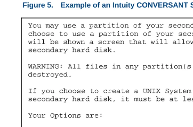
Figure 5. Example of an Intuity CONVERSANT Screen Requesting Information
You may use a partition of your secondary hard disk. If you choose to use a partition of your secondary hard disk you will be shown a screen that will allow you to partition your secondary hard disk.
WARNING: All files in any partition(s) you delete will be destroyed.
If you choose to create a UNIX System partition on your secondary hard disk, it must be at least 40 MBs.
Your Options are:
1. Do not use a partition of the secondary hard disk for the UNIX System.
2. Use a partition of the secondary hard disk for the UNIX System.
Keyboard and Telephone Keypad Representations
• Keys that you press on your terminal or PC are represented as small capitalized B O L D text. For example, an instruction to press the enter key is shown as
Press E N T E R.
• Two or three keys that you press at the same time on your terminal or PC (that is, you hold down the first key while pressing the second and/or third key) are represented in small capitalized B O L D text. For example, an instruction to press and hold the Alt key while typing the letter “d” is shown as
Press A LT + D.
• Function keys on your terminal, PC, or system screens, also known as soft keys, are represented as small capitalized B OL D text followed by the function or value of that key enclosed in parentheses. For example, an instruction to press function key 3 is shown as
Press F 3 (Choices).
• Keys that you press on your telephone keypad appear in small capitalized
B O L D text. For example, an instruction to press the first key on your telephone keypad is shown as
Press 1 to record a message.
Screen Displays • Values, system messages, field names, prompts that appear on the screen, and simulated screen displays are shown in typewriter-style
constant width type, as in the following examples:
Enter the number of ports to be dedicated to outbound traffic in the
Maximum Simultaneous Ports field.
Alarm Form Update was successful. Press <Enter> to continue.
• The sequence of menu options that you must select to display a specific screen or submenu is shown as follows:
Start at the Voice Administration menu and select:
In this example, you would access the Intuity CONVERSANT Voice Administration menu and select the Configuration Management menu. From the Configuration Management menu, you would then select the Database Administration option.
Other Typography • Commands and text you type in or enter appear in bold type, as in the following examples:
Enter change-switch-time-zone at the Enter command: prompt. Type high or low in the Speed: field.
• Command variables are shown in bold italic type when they are part of what you must type in, and in blue italic type when they are referred to, for example:
Enter ch ma machine_name, where machine_name is the name of the call delivery machine you just created.
Safety and Security Alert Labels
This book uses the following symbols to call your attention to potential problems that could cause personal injury, damage to equipment, loss of data, service interruptions, or breaches of toll fraud security:
!
CAUTION:
Indicates the presence of a hazard that if not avoided can or will cause minor personal injury or property damage, including loss of data.
WARNING:
!
Indicates the presence of a hazard that if not avoided can cause death or severe personal injury.
!
DANGER:
Indicates the presence of a hazard that if not avoided will cause death or severe personal injury.
!
SECURITY ALERT:
Getting Help
The Intuity CONVERSANT system provides online help to assist you during installation, administration, and application development tasks.
To use the online help:
• Press F 1 (Help) when you are in a menu or window.
The first time you press F 1, the system displays information about the currently active window or menu.
~ When you are in a window, the help explains the purpose of the window and describes its fields.
~ When you are in a menu, the help explains how to use menus. If you press F 1 again, the system displays a General Help screen that explains how to use the online help.
• Press F 2 (Choices) when you are in a field.
The system displays valid field choices either in a pop-up window or on the status line directly above the function keys.
Technical Assistance
Contact Numbers Technical assistance on the Intuity CONVERSANT product is available through the following telephone contacts:
• In the United States
~ Call 1-800-313-2121
extension 81089 for assistance with the Intuity CONVERSANT system extension 85474 for assistance integrating the system with Lucent or non-Lucent switches
• In Canada
WAITING FOR PAT MCQUADE TO VERIFY CANADIAN NUMBERS 416-756-8315
~ Eastern Canada — call 1-800-363-1882
~ Ontario and western Canada — call 1-800-387-4268
• In any other country
~ Call your local distributor or check with your project manager or systems consultant.
Web Site The following customer support web site contains technical resources:
Included at this site is the Electronic Library Material Online (ELMO) system, which contains over one thousand online documents for Lucent Technologies products.
Related Resources
Additional documentation and training material is available for you to learn more about the Intuity CONVERSANT product.
Training To obtain training on the Intuity CONVERSANT product, contact the BCS Education and Training Center at one of the following numbers:
• Organizations within Lucent Technologies (904) 636-3261
• Lucent Technologies customers and all others (800) 255-8988 You can also view information on Intuity CONVERSANT training at the Global Learning Solutions (GLS) web site at one of the following web links:
• Organizations within Lucent Technologies
http://training.gls.lucent.com
• Lucent Technologies customers and all others
http://www.lucenttraining.com
• For technicians doing repairs on Intuity CONVERSANT V7.0 systems
~ BTT509H, CONVERSANT Installation and Maintenance Voice Information System
• For technicians and administrators
~ BTC344M, Intuity CONVERSANT V7 Administration Overview (CD-ROM)
• For application developers
~ BTC128H, Introduction to Script Builder
~ BTC166H, Introduction to Voice@Work
~ BTC204H, Intermediate Voice@Work
~ BTC301H, Advanced CONVERSANT Programming
Documentation Appendix A, "Documentation Guide," in Intuity CONVERSANT System Version 7.0 System Description, 585-313-204, describes in detail all books included in Intuity CONVERSANT documentation library and referenced in this book.
Additional Suggested Documentation
It is suggested that you also obtain and use the following book for information on security and toll fraud issues:
• GBCS Products Security Handbook, 555-025-600
Obtaining Printed Versions of the Documentation
See Documentation Ordering Information on page viii of Copyright and Legal Noticesfor information on how to purchase Intuity CONVERSANT
documentation in printed form. You can also print documentation locally from the CD-ROM (see Printing the Documentation on page xl).
Using the CD-ROM Documentation
Lucent Technologies ships the documentation in electronic form. Using the AdobeAcrobat Reader application, you can read these documents on a Windows PC, on a Sun Solaris workstation, or on an HP-UX workstation. Acrobat Reader displays high-quality, print-like graphics on both UNIX and Windows platforms. It provides scrolling, zoom, and extensive search capabilities, along with online help. A copy of Acrobat Reader is included with the documents.
Setting the Default Magnification
You can set your default magnification by selecting File | Preferences | General. We recommend the Fit Page option.
Adjusting the
Window Size On HP and Sun workstations, you can control the size of the reader window by using the -geometry argument. For example, the command string
acroread -geometry 900x900 mainmenu.pdf opens the main menu with a window size of 900 pixels square.
Hiding and Displaying Bookmarks
By default, the document appears with bookmarks displayed on the left side of the screen. The bookmarks serve as a hypertext table of contents for the chapter you are viewing. You can control the appearance of bookmarks by selecting View | Page Only or View | Bookmarks and Page.
Using the Button
Bar The button bar can take you to the book’s Index, table of contents, main menu, and glossary. It also lets you update your documents. Click the
corresponding button to jump to the section you want to read.
Using Hypertext Links
Hypertext links appear in blue underlined text. These links are shortcuts to other sections or books.
Navigating with
Double Arrow Keys The double right and double left arrows (Acrobat Reader window are the go-back and go-forward functions. The go-and ) at the top of the
Searching for Topics
Acrobat has a sophisticated search capability. From the main menu, select Tools | Search. Then select Master Index.
Displaying Figures If lines in figures appear broken or absent, increase the magnification. You might also want to print a paper copy of the figure for better resolution.
Printing the Documentation
Note: For information on purchasing printed copies of the documents, see Obtaining Printed Versions of the Documentation on page xxxviii.
If you would like to read the documentation in paper form rather than on a computer monitor, you can print all or portions of the online screens.
Printing an Entire Document
To print an entire document, do the following:
1 From the documentation main menu screen, select one of the print-optimized documents. Print-print-optimized documents print two screens to a side, both sides of the sheet on 8.5x11-inch or A4 paper.
3 Enter the page range you want to print, or select All. Note that the print page range is different from the page numbers on the documents (they print two to a page).
4 The document prints.
5 Close the file. Do not leave this file open while viewing the electronic documents.
Printing Part of a Document
To print a single page or a short section, you can print directly from the online version of the document.
1 Select File | Print.
2 Enter the page range you want to print, or select Current. The document prints, one screen per side, two sides per sheet.
How To Comment on This Book
Comment Form A comment form, available in paper and electronic versions, is available via the documentation CD-ROM. To use the comment form:
1 Select Comments from the Main Menu of the CD-ROM.
2 Follow the instructions provided on the CD-ROM to do one of the following:
~ Print the paper version of the form, complete it, and either fax or mail it to us.
~ Access a Lucent Technologies website where you can enter your comments electronically.
Contact Us Directly If you prefer not to use the comment form, you can contact us directly at the following address or fax number.
Note: Direct your correspondence to the attention of the Lucent Technologies Intuity CONVERSANT writing team. Be sure to mention the title of the book on which you are commenting. Lucent Technologies
GLS Information Development Division Room 22-2H15
1
Analog Telephony Interfaces
Overview
This chapter describes the Tip/Ring and FAX analog telephony interfaces available with the CONVERSANT system’s base and optional software and the requirements that must be met to implement these interfaces.
Introduction to Analog Communications
In its analog configuration, the system provides nearly universal connectivity to existing private branch exchange (PBX) and automatic call distribution (ACD) customer-premise equipment. It also allows standard interfaces to such widespread network services as Public Switched Telephone Networks (PSTNs) and Centrex service.
The following base analog telephony features make the CONVERSANT system compatible with a variety of domestic PBXs or ACDs (including the Lucent DEFINITY Communications Systems Generic 1, 2, and 3, System 85, System 75, System 25, DIMENSION 2000, etc.):
• The system can perform switch-hook-flash transfers (also known as register recall) using the functions of the PBX or ACD or Centrex service. It can also determine if the extension to which the call was transferred is busy or there is no answer and whether an alternative message or action should occur.
• In addition to switch-hook-flash transfers, the system supports transfer with a call bridge connection through the system. This bridging can be done with both digital and analog connections. Table 1 on page 4 lists the analog line capabilities supported by call bridging.
(The wink signal is a momentary break in loop current: typically 600 mSec.) Because these capabilities allow the system to know when a caller hangs up, the system rarely transfers a “ghost” call, but instead allows the voice script to terminate quickly and be ready for the next call. Note: Far-end caller disconnect detection through a wink signal or a call
progress tone must also be supported by the PBX or ACD. Lucent DEFINITY Communications Systems Generic 1, 2, and 3, System 85, System 75, System 25, and DIMENSION 2000 switches provide the signaling needed to notify the CONVERSANT system of far-end caller disconnect. Other PBX systems may not. In these cases, implement script timeouts to ensure script termination.
• Outdialing for call transfer can be done with either touch tone or dial pulse (sometimes called decadic dialing or loop disconnect signaling).
• With custom software, the system can be programmed to transfer calls using dial access codes (rather than switch-hook-flash) to support PBXs that use this method of call transfer.
Trainable dial tone, software-settable switch hook flash duration, and wink signal duration also add to the system’s flexibility.
.
Table 2 on page 4 details the maximum number of analog and digital lines supported without call bridging.
Table 1. Maximum Digital Trunks/Analog Lines Supported by Call Bridge
MAP/100P, 100C MAP/40P
Answer/Originate Outbound/Bridging Answer/Originate Outbound/Bridging
60 digital T1 (linked) 60 digital T1 24 digital T1 (linked) 24 digital T1 36 analog Tip/Ring 36 analog Tip/Ring 24 analog Tip/Ring 24 analog Tip/Ring 72 analog Tip/Ring 48 digital T1 24 analog Tip/Ring 24 digital T1 96 digital T1 24 analog Tip/Ring 24 digital T1 24 analog Tip/Ring 96 digital T1 24 digital T1
Table 2. Maximum Digital Trunks/Analog Lines Supported without Call Bridge
MAP/100P, 100C MAP/40P MAP/5P
Answer/Originate Answer/Originate Answer/Originate
Analog 72 48 24
Analog Connections to a 5ESS Switch
Analog lines from the local service provider supply the physical interface between the switch and the CONVERSANT system. The lines should be configured as a standard 2500 analog set on the switch. See Chapter 5, “Switch Interface Administration,” of Intuity CONVERSANT System Version 7.0 Administration, 585-313-501, for an extended list of tunable parameters available with the various switch integration packages.
Analog Connections to Lucent PBXs
• The domestic PBX must provide analog service using CCITT
(International Telephone and Telegraph Consultative Committee) and LSSGR (LATA Switching Systems Generic Requirements) standards. All analog station packs on DEFINITY switches and DIMENSION 2000 meet these standards. However, the LC03 circuit card on the DIMENSION 2000 and the SN229 circuit card on the System 85/G2 are not recommended for connection to the CONVERSANT system.
• Each analog port on the switch must be configured to communicate as a standard 2500 analog set with the ability to transfer and conference calls. Each port requires a station number, an appropriate Class of Service (COS)/Class of Restriction (COR), and a hardware port location. Note: On DEFINITY G1/G3 switches, ports routed to the Intuity
CONVERSANT system must not have data restrictions in the COR, and “redirect notification” must be set to “y” if the
CONVERSANT system is to transfer calls to ACD splits staffed by Auto Answer (zip tone) agents.
• If you are using a MERLIN LEGEND communications system:
~ All analog trunks receiving calls from and getting calls for the CONVERSANT system must provide reliable disconnect.
~ All Tip/Ring lines originating from the MERLIN LEGEND switch connected to the Intuity CONVERSANT system must be setup in a MERLIN LEGEND calling group as type “Generic VMI.”
~ You must administer the lines connected to the system with “outside line” dial tone. Refer to “Inside Dial Tone” in the MERLIN LEGEND Communications System Installation, Programming, and Maintenance
for additional information.
Analog Connections to Other Switches
The CONVERSANT system can interface with other switches if differences in communication protocols and parameter settings are taken into account. The proper setting of these parameters on both the switch and the
Tip/Ring Interface
The Tip/Ring interface is provided through an analog (loop-start) Tip/Ring circuit card, with multiple 2-wire interfaces to the PBX, ACD, central office (CO), or foreign PSTN services. In addition to providing a physical network interface, the Tip/Ring circuit card provides speech encoding and playback, dual tone multifrequency (DTMF) recognition, call supervision, and
intraswitch call classification for intelligent transfers. See Introduction to Analog Communications on page 2 for additional information.
Tip/Ring Connectivity
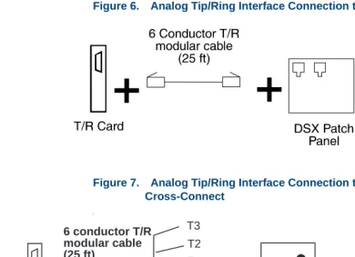
Figure 6 on page 9 through Figure 8 on page 10 show typical Tip/Ring connections from the Intuity CONVERSANT system. See the “Installing or Replacing Circuit Cards” chapter in the maintenance book for your platform for information on installing a Tip/Ring circuit card.
Note: The connectivity diagrams provide examples of Tip/Ring
Figure 6. Analog Tip/Ring Interface Connection to a DSX Patch Panel
Figure 7. Analog Tip/Ring Interface Connection to a Type 66 or 110 Cross-Connect
t
+
T/R Card
+
To Central Office
Cross Connect Type 66 or Type 110 T2
T1
R2 R1
R3 T3 6 conductor T/R
The AYC30 circuit card has 8-pin jacks where the outside pins are available for a rarely used “Earth Recall” feature.
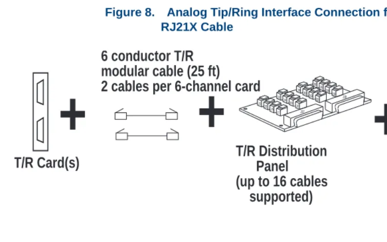
Figure 8. Analog Tip/Ring Interface Connection from Distribution Panel Using RJ21X Cable
+
T/R Card(s)
+
J1 J2 J3 J4 J5 J6 J7 J8 J9 J10 J12 J13 1 J 1 5 J1 4 J1 6 J1 7 J1 J18T/R Distribution
Panel
(up to 16 cables
supported)
6 conductor T/R
modular cable (25 ft)
2 cables per 6-channel card
DSX Patch Panel
or
Cross Connect
+
50-pin
RJ-21X male/female
cable (25 ft)
Tip/Ring Telephony Interface
Specifications
Tables from Table 3 on page 11 through Table 6 on page 14 detail the various Tip/Ring telephony interface specifications.
Note: The wink detection and flash duration attributes can be changed through the Analog Interfaces screen described in Chapter 5, “Switch Interface Administration,” of Intuity CONVERSANT System Version 7.0 Administration, 585-313-501.
Table 3. Tip/Ring Circuit Card General Specifications
Attribute Value
Type of service Loop-start POTS
Loop current detection 15 mA minimum
Ringing voltage detection 88 VRMS at 20 Hz (nominal) Ringer equivalence for
Tip/Ring
1.0 B for AYC10
Wink detection*
* These attributes are adjustable through the Analog Switch Interface (ASI) packages.
80–800 msec
Flash duration* 40–1550 msec
Register recall* Timed break
Table 4. Tip/Ring Circuit Card DTMF Tone-Detection Specifications
Attribute Value
Digits 0–9, asterisk (*), pound sign (#), A – D Amplitude*
* This attribute is adjustable through the Analog Switch Interface (ASI) package. +1 to -30 dBm total power (nominal tones) On/Off timing 80 msec minimum on, 23 msec off
Gaps bridged 23 msec
Signal/noise ratio 23 dB (nominal tones at -19 dBm total power) Twist +4 to -8 dB (high to low tone)
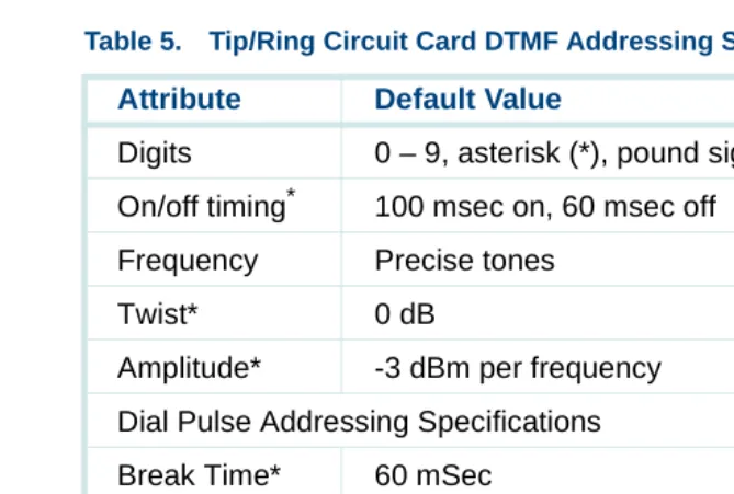
Table 5. Tip/Ring Circuit Card DTMF Addressing Specifications
Attribute Default Value
Digits 0 – 9, asterisk (*), pound sign (#), A – D On/off timing*
* These attributes are adjustable through the Analog Switch Interface (ASI) packages.
100 msec on, 60 msec off Frequency Precise tones
Twist* 0 dB
Amplitude* -3 dBm per frequency Dial Pulse Addressing Specifications Break Time* 60 mSec
Make Time* 40 mSec
Table 6. Tip/Ring Circuit Card Default Call Progress Tone Detection Specifications Tone Frequency (Hz)* Amplitude (dBm)* S/N Ratio (dB) Maximum Twist (dB) Frequency Deviation (%) Cadence*
Dial 350 + 440 † +1 to -24 55 +3 +/-0.5 Present for
1 sec Stutter dial
(recall dial tone)
350 + 440 † +1 to -24 55 +3 +/-0.5 3 cycles of
120–150 msec on, 120–150 msec off followed by 1 sec on
Ringback 440 + 480 +1 to -24 55 +3 +/-0.5 1000–2000
msec on, 3000–4000 msec off
1. These attributes are adjustable through the Analog Switch Interface (ASI) pack-ages.
Busy 480 + 620 +1 to -24 55 +3 +/-0.5 60 IPM,
250–500 msec on, 500–650 msec off Reorder (Fast busy)
480 + 620 +1 to -24 55 +3 +/-0.5 120 IPM,
180–250 msec on, 250–350 msec off
Table 6. Tip/Ring Circuit Card Default Call Progress Tone Detection Specifications
Tone Frequency (Hz)* Amplitude (dBm)* S/N Ratio (dB) Maximum Twist (dB) Frequency Deviation (%) Cadence*
Tip/Ring Circuit Card Administration
Placing a card in the INSERV state allows it to be used for the purpose (play, code, etc.) for which it is allocated in the application. You may need to manually place a Tip/Ring card into service if:
• After first installing the card or changing switch integration parameters, the voice system did not automatically place the card in the INSERV state.
• The card was placed in the MANOOS state.
• A diagnostic procedure failed (that is, placed that card in the MANOOS or BROKEN state).
To change the state of the Tip/Ring cards to INSERV, use the procedures described in Chapter 3, “Voice System Administration,” of Intuity
CONVERSANT System Version 7.0 Administration, 585-313-501.
Transmission Level Plan
Most switch designs implement a TLP with a “built-in” gain of -3 dB (often called insertion loss) in each Tip/Ring loop of a station-set-to-station-set connection, for a total gain of -6 dB from end to end (Figure 9 on page 17). The CONVERSANT system default TLP implements this same strategy; that is, the system default TLP attempts to make the end-to-end gain of voice signals passing through it equal to -6 dB. (There are reasons to implement other strategies, however, see Reasons for Deviating from the Default IVOL and OVOL Settings on page 307 in Appendix A, Transmission Level
Adjustment)
Figure 9. Typical Switch Transmission Level Plan for Station-Set-to-Station-Set Connection
Switch
TSM
Station
Set A
Station
Set B
Tip/Ring
Tip/Ring
Note: The IVOL, OVOL, and TDM output gains are system-wide parameters for analog interfaces and can be changed on a per-card basis for digital interfaces. These parameters can be modified via the Switch Interface Administration screens as described in Chapter 5, “Switch Interface Administration,” of
Intuity CONVERSANT System Version 7.0 Administration, 585-313-501. Gains can also be overridden on a per-channel basis by an Intuity Response Application Programming Interface (IRAPI) application. However, even with IRAPI, the IVOL cannot be overridden for speech recording on a Tip/Ring channel. Refer to
Table 7. Tip/Ring Circuit Card Transmission Level Plan
Attribute Value
Input gain 0 dB fixed
Output gain 0 dB fixed
Incoming speech volume (IVOL) – card voice coding only
Selectable from -9 to +12 dB
Outgoing speech volume (OVOL) – card voice playback only
Selectable from -9 to +12 dB
Development with Advanced Methods, 585-313-203, for the IRP_PLAYGAIN and IRP_RECORD_GAIN parameters under IrPARAMETERS(4IRAPI).
See Appendix A, Transmission Level Adjustment, for more information about adjustment of IVOL and OVOL levels.
Fax Interface
Facsimile (fax) communications involve transmitting graphic and text images between fax machines and other devices via standard telecommunications networks.
For a general discussion of the Script Builder FAX Actions feature package, refer to the Intuity CONVERSANT System Version 7.0 System Description,
585-313-204.
FAX Provisioning
FAX Application Development Issues
The CONVERSANT system can invoke fax services through Script Builder applications.
Script Builder FAX Actions
The Script Builder FAX Actions allow you to include fax communications in any Script Builder application. Script Builder FAX Actions offer the following capabilities:
• Transmit a prestored graphic image to a caller
• Transmit a dynamically created text image (file) to a caller
• Create a text file dynamically for transmission to the caller
• Create customized cover pages
2
Digital Telephony Interfaces
Overview
This chapter describes the T1, Line Side T1 (LST1), E1, Line Side E1 (LSE1), and Primary Rate Interface (PRI) digital telephony interfaces available with the CONVERSANT system. It also describes optional software and the requirements that must be met to implement these interfaces.
Introduction to Digital Communications
A digital T1 (E&M) or E1 (CAS) circuit (trunk) allows the system to connect to digital network facilities such as a central office (CO) switch. Digital
connections between a DEFINITY switch and the CONVERSANT system can be through PRI, T1 (E&M), E1 (CAS), LST1, or LSE1. (Generally only E1 or T1 service is offered in a given area.)
Advantages of Digital Service
Analog configurations require one analog connection between the
Advantages of PRI
PRI acts as a powerful interface between intelligent equipment such as PBXs and computers. Furthermore, PRI is widely used for access to features provided over the larger network such as automatic number identification (ANI).
See Primary Rate Interface on page 49 for a detailed discussion of features that accompany the use of PRI.
Network Communications
A T1 digital circuit carries information at 1.544 Mbps, and consists of 24 DS-0 channels. Each DS-0 channel operates at 64 Kbps, and is the equivalent of one incoming data line. An AYC21 interface card has a (mechanical) switch that allows you to choose either the T1 or E1 interface. The E1 interface is very similar to the T1 except that an E1 digital circuit carries information at a rate of 2.048 Mbps and consists of 30 B channels and 2 signaling and framing channels. Each B channel is the equivalent of one incoming data line. T1 connections also provide dialed number identification service (DNIS) information to further automate incoming calls for customers with multiple 800 or 900 numbers. Table 2 on page 4 shows the maximum number of digital lines that are supported on each CONVERSANT platforms.
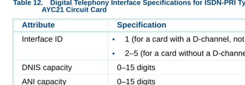
T1, E1, and Integrated Services Digital Network (ISDN) PRI support trunk interfaces. ISDN PRI can operate at either the T1 or E1 rate. A T1-PRI interface contains either 23 B+D channels or 24 B channels that are
Interconnection with PBX
Line-side connections between a DEFINITY switch and an Conversant system may be either by means of either a LST1 interface or a LSE1 interface. LST1 connections to a Galaxy ACD are also supported. See Line Side Digital Interface on page 43 for more information.
The default gain in each B channel is 0 dB. Transmission levels are discussed under Transmission Level Plan on page 300 in Appendix A, Transmission Level Adjustment. Possible reasons for adjusting gain are given under Reasons for Deviating from the Default IVOL and OVOL Settings on page 307 also in Appendix A.
These LST1 and LSE1 channels also support the Adjunct/Switch Application Interface (ASAI) feature when used with DEFINITY switches. (ASAI can be used for more advanced call control and to collect information such as ANI and DNIS.) See Advantages of Using the ASAI Feature on page 64 in
Chapter 3, Adjunct/Switch Application Interface.
T1 (E&M), E1 (CAS), and PRI connections to a DEFINITY switch are supported as well as LST1 and LSE1, but LST1 and LSE1 are generally preferable. LST1 and LSE1 support switch-hook-flash transfers, but T1 (E&M), E1 (CAS), and PRI do not.
The system supports call bridging through a digital connection. Call bridges can also be used to simulate a transfer, but this consumes channel
Digital Telephony Interface Specifications
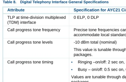
Table 8 on page 26 details the general digital telephony interface specifications for all T1/E1 protocols.
Table 8. Digital Telephony Interface General Specifications
Attribute Specification for AYC21 Circuit Card
Physical connector BNC co-ax or
8-pin modular
FCC registration AS5USA-24091-XD-E
Safety approval • UL 1459 type approval for US markets
• CSA 22.2 type approval for Canadian markets
• EN 60950 type approval for European markets
• AS3260 and TS-001 for Australian markets T1 Signal regeneration CSU required over 200 meters (655 feet) T1 Loopback capability CSU required for remote capability Transmission Level Point (TLP)
at DS-1 interface
0 ELP, 0 DLP
TLP at time-division multiplexed (TDM) interface
0 ELP, 0 DLP
Call progress tone frequency Precise tone frequencies can be tuned to accommodate local standards
Call progress tone levels -10 dBm total (nominal)
This value is tunable through digital switch interface packages.
Call progress tone timing • Ringing –on/off: 2 sec on, 4 sec off
• Busy – on/off: 0.5 sec on, 0.5 sec off
Values are tunable through digital switch interface packages
Call progress tone detection Supported with Line Side DEFINITY protocol (either at T1 or E1 transmission rate)
DS-1 timing source Slave to DS-1 source (loop timed) DS-1 timing (free running) Stratum 4
Table 8. Digital Telephony Interface General Specifications
Attribute Specification for AYC21 Circuit Card
Suggested channel service unit (CSU) types for use at T1 rate
• Paradyne (PEC 21581-ESF
• Verilink 551VST List 2, or equivalent
Supported configurations Tie trunk (robbed-bit E&M), E1 (CAS), ISDN-PRI (E1/T1), LSE1, LST1
Dual tone multifrequency (DTMF) output timing
70 msec on, 70 msec off
This value is tunable through digital switch interface packages.
DTMF output levels -8 dBm per frequency (nominal)
This value is tunable through digital switch interface packages.
Table 8. Digital Telephony Interface General Specifications
Attribute Specification for AYC21 Circuit Card
DTMF receivers LATA Switching Systems Generic Requirements (LSSGR) compatible. Note: If DTMF muting is on for a call, the DTMF receiver’s minimum on time for detection is increased and may not meet LSSGR requirements. DTMF muting does not impact LSSGR compatibility of DTMF receivers during call setup, that is S digits.
This value is tunable through digital switch interface packages.
Number of receivers: T1 24 (1 per DS-0 channel) Number of receivers: E1 30 (1 per B-channel)
Table 8. Digital Telephony Interface General Specifications
Attribute Specification for AYC21 Circuit Card
Digital Connectivity
The MAP/40P, MAP/100P, and MAP/100C support up to five T1 circuit cards. A SSP circuit card is required if you are using T1 circuit cards in coding and playback situations.
Note: Each SSP circuit card supports up to 120 channels of
simultaneous speech playback using adaptive differential pulse code modulation (ADPCM) 32-Kbps coded speech.
See the “Installing or Replacing Circuit Cards” chapter in the maintenance book for your platform for information on installing digital and SSP circuit cards.
Figure 10 on page 31 and Figure 11 on page 31 show examples of typical digital connections to trunks and switches. Table 10 on page 38 details the digital telephony specification for the T1.5 Robbed-bit E&M protocol. Use
Figure 10. Example of AYC21 Coaxial Connections to a DEFINITY G3 Switch
Figure 11. Example of AYC21 Twisted-Pair Connections to a DEFINITY G3 Switch
RX TX
AYC21 888B
Plug into 25-pair
Connector on
Co-ax Cable
RX TX
AYC21
Twisted-Pair
TN464 Series Circuit Pack
Port 8
Channel Service Unit Connectivity (T1 Only)
The T1 interface circuit card is connected to a CSU or directly to the DS-1 terminal block to establish T1 connections to a CO.
A CSU performs certain line-conditioning and equalization functions and responds to loopback commands from the CO. A CSU regenerates digital signals, monitors them for problems, and provides a way to test the digital circuit. A CSU is not always needed. However, a CSU is required if any of the following situations applies to the system setup:
• The CONVERSANT system is more than 200 meters (655 feet) from the signal source. The signal source may be a DSX or the last T1 repeater. Here, the CSU regenerates the received signal and properly attenuates the transmitted signal to prevent crosstalk.
• The CONVERSANT system is terminating the T1 trunk from outside the building. Here, the CSU provides the primary lightning and surge protection as required by FCC Rules Part 68.
• The T1 loop is not dry (that is, the loop is powered by either 110 VAC, +24 VDC or -48 VDC sources).
• You want to use the remote loopback and/or extended super frame (ESF) maintenance features. Here, the CSU recognizes the in-band bit patterns that signal it to loopback the incoming signal or to perform other
On some types of CSUs, the connector on the T1 cable can plug into the AYC21 circuit card and the cable terminates at a 15-pin D subminiature connector to the CSU (Figure 12 on page 33). On other types, you must cut off the CSU connector and slide latch and strip and connect the wires (Figure 13 on page 34).
Figure 12. Example of T1 Interface Connection to a CSU (From an AYC21 Circuit Card
)
CSU
15-pin to 8-pin cable 8-pin to 15-pin-subminiature
Figure 13. Example of AYC21 Connection to a CSU with Wire Wrapping Posts
E1-CAS (Channel Associated Signaling) Interface
The AYC21 circuit cards can operate with Channel Associated Signaling (CAS). This interface (at the E1 rate: 2.048 Mbits/sec) uses signaling bits associated with each channel to determine the state of the channel. Thirty voice channels are supported on each link.
Several country specific signaling protocols have been developed using E1-CAS. Contact your local Lucent Technologies technical representative for more information about locally supported protocols.
8-pin modular
AYC21
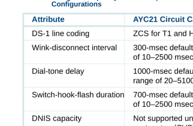
Table 9. Digital Telephony Interface Specifications for E1-CAS Configurations
Attribute Specification
DS1 Rate 2.048 Mbits/sec (ITU G.703)
DS1 framing/line coding HDB3 (ITU G.704, G.705) Cyclic Redundancy Check
(CRC)
(ITU G.706) May be set to YES or NO; must match the CRC setting of the network entity connected to the AYC21
Physical Connector Options 120 Ohm twisted pair on RJ-48C modular jack or 75 Ohm BNC jacks
PCM Companding Rule A-Law or Mu-Law. (ITU G.711)
Line Signaling ITU System R2, Q.421 compliant; variations by specific protocol are supported
Address Signaling Options (Register Signaling) Incoming and Outgoing
DTMF (Touch Tone) ITU system MFC, Q.440, Q.441; variations for specific protocols are supported by table entries; Dial pulse (slower than DTMF or MFC)
Outgoing Destination Number
15 digits max
Outgoing ANI Number 15 digits max (if supported by protocol)
E1 Switch Integration and Administration
Switch Integration for E1-CAS is done using the Digital Interfaces screen. This screen is described in Chapter 5, “Switch Interface Administration,” of
Intuity CONVERSANT System Version 7.0 Administration, 585-313-501. You must select one of the E1-CAS protocols that correspond to optional
packages loaded on the INTUITY CONVERSANT system. Incoming Address: (DNIS) 15 digits max
Incoming ANI Number 15 digits max (if supported by protocol) Audible Alerting Tones on
Incoming Calls
Ring, busy, reorder; variations by country supported
Call Progress Tone Recognition on Outbound Calls
Not supported
Call Transfer Capability Not supported
Table 9. Digital Telephony Interface Specifications for E1-CAS Configurations
Attribute Specification
Placing a card in the INSERV state allows it to be used for the purpose for which it is allocated in the application. After performing switch integration on the E1 circuit card for the CAS protocol, you may need to manually place an E1 circuit card into service if:
• After first installing the card or changing switch integration parameters, the voice system did not automatically place the card in the INSERV state.
• The card was placed in the MANOOS state.
• A diagnostic procedure failed (that is, placed that card in the MANOOS or BROKEN state).
To change the state of the E1 circuit cards to INSERV, use the steps described in Chapter 3, “Voice System Administration,” of Intuity CONVERSANT System Version 7.0 Administration, 585-313-501.
E1 Connections
T1 E&M Interface
The T1 circuit cards accept an ISDN PRI or DS-1 two-way digital trunk and convert it to two-way analog audio channels. Because of the bandwidth and transmission differences of each trunk, ISDN PRI and DS-1 offer different numbers of converted channels. A standard 1.544-Mbps DS-1 format trunk converts to 24 DS-0 channels. These 64-Kbps channels can provide 24 two-way audio channels.
Table 10. Digital Telephony Interface Specifications for T1 E&M Type Configurations
Attribute Specification
DS-1 framing D4 type only
DS-1 line coding Zero code suppression (ZCS) Protocol Robbed-bit (4-wire) E&M Alerting in/out Wink/wink
Wink generation 230 msec default (selectable: 20–2500 msec) Wink detection range 10–350 msec
Addressing (outgoing) • DTMF (touch tone)
• MF (multifrequency)
• Dial pulse (slower than DTMF or MF) Number of digits 15-digit maximum
Addressing (incoming) • DTMF (touch tone)
• MF (multifrequency)
• Dial pulse (slower than DTMF or MF)
Number of digits (DNIS) Will wait for up to 16 digits (selectable); can also be provisioned not to wait for digits
Initial digit timer Will wait up to 4 seconds for first digit; can also be provisioned not to wait for digits
Interdigital timer Will wait up to 2 seconds between digits
Audible ring starts As soon as the selected number of digits is received or when one of the above timers expire, whichever occurs first DNIS capacity 0–16 digits
Table 10. Digital Telephony Interface Specifications for T1 E&M Type Configurations
Attribute Specification
T1 Switch Integration and Administration
Switch integration for T1 is done using the Digital Interfaces screen. This screen is described in Chapter 5, “Switch Interface Administration,” of Intuity CONVERSANT System Version 7.0 Administration, 585-313-501. You must select T1 A/B robbed-bit E&M Protocol from the Digital Interfaces screen. (See Switch Integration and Administration on page 46 and Primary Rate Interface on page 49 for information on performing switch integration for those types of protocols.)
ANI capacity Not supported
Transfer capability Not supported
Table 10. Digital Telephony Interface Specifications for T1 E&M Type Configurations
Attribute Specification
Placing a card in the INSERV state allows it to be used for the purpose for which it is allocated in the application. After performing switch integration on the T1 circuit card for the E&M protocol, you may need to manually place a T1 circuit card into service if:
• After first installing the card or changing switch integration parameters, the voice system did not automatically place the card in the INSERV state.
• The card was placed in the MANOOS state.
• A diagnostic procedure failed (that is, placed that card in the MANOOS or BROKEN state).
To change the state of the T1 circuit cards to INSERV, use the steps described in Chapter 3, “Voice System Administration,” of Intuity CONVERSANT System Version 7.0 Administration, 585-313-501.
T1 Connections
Digital Application Development Issues
The AYC21 circuit card recognizes call progress tones and therefore supports flash transfers over LSE1 or LST1. The AYC21 circuit card does not, however, support flash transfer over T1 (E&M), E1 (CAS), or PRI. See
Line Side Digital Interface on page 43 for more information.
Simulated transfers using digital cards can be performed over call bridges. In the analog Tip/Ring or line-side digital en