IOP Conf. Series: Earth and Environmental Science 18 (2014) 012030 doi:10.1088/1755-1315/18/1/012030
Calibration of high resolution digital camera based on
different photogrammetric methods
N F A Hamid and A Ahmad
Department o f Geoinformation, Faculty o f Geoinformation & Real Estate, Universiti Teknologi Malaysia, 81310 Johor Bahru, Johor, M alaysia
E-mail: [email protected]
Abstract. This paper presents method of calibrating high-resolution digital camera based on different configuration which comprised of stereo and convergent. Both methods are performed in the laboratory and in the field calibration. Laboratory calibration is based on a 3D test field where a calibration plate of dimension 0.4m x 0.4m with grid of targets at different height is used. For field calibration, it uses the same concept of 3D test field which comprised of 81 target points located on a flat ground and the dimension is 9m x 9m. In this study, a non-metric high resolution digital camera called Canon Power Shot SX230 HS was calibrated in the laboratory and in the field using different configuration for data acquisition. The aim of the calibration is to investigate the behavior of the internal digital camera whether all the digital camera parameters such as focal length, principal point and other parameters remain the same or vice-versa. In the laboratory, a scale bar is placed in the test field for scaling the image and approximate coordinates were used for calibration process. Similar method is utilized in the field calibration. For both test fields, the digital images were acquired within short period using stereo and convergent configuration. For field calibration, aerial digital images were acquired using unmanned aerial vehicle (UAV) system. All the images were processed using photogrammetric calibration software. Different calibration results were obtained for both laboratory and field calibrations. The accuracy of the results is evaluated based on standard deviation. In general, for photogrammetric applications and other applications the digital camera must be calibrated for obtaining accurate measurement or results. The best method of calibration depends on the type of applications. Finally, for most applications the digital camera is calibrated on site, hence, field calibration is the best method of calibration and could be employed for obtaining accurate measurement.
Introduction
Digital camera calibration becomes essential to achieve the precision o f the measurement task. However, when talk about non-metric digital camera, there are consideration must be aware the internal especially geometry camera instability. Camera parameters usually could be recovered through camera calibration process which comprised o f focal length (c), principal point offset (xp, yp)
which represent the coordinates o f the center o f the image, radial lens distortion (k1, k2, k3) and tangential lens distortion (p1, p 2). Nowadays, various techniques o f camera calibration were introduced several years ago as new flexible technique [1], targetless [2], multi-camera [3-4], automatic approach [5], simple calibration [6], on-the-job calibration [7-8], self-calibration [8-11] and so on but there are not many calibration techniques in which the images taken using UAV system.
IOPConf. Series: Earth and Environmental Science 18 (2014) 012030 doi:10.1088/1755-1315/18/1/012030
Practically, these UAVs are equipped with devices such as camera, sensors, communication tools and other payloads to perform certain activity. The UAVs have several advantages such as low cost operation, simple manipulation, high resolution, flexibility and others. According to [13], the advantages in developing the technology o f UAV for low altitude photogrammetric mapping are to perform aerial photography at cloudy day, to get full image o f object from the top, and to supply a low cost and easy system for high frequency needs o f aerial photogrammetric survey. UAV system is not limited by human on aircraft for data collection in dangerous or hazardous environment without risk o f pilot. Therefore, the aim o f this study is the establishment o f an efficient and accurate digital camera calibration method using Hexacopter UAV (rotary wing) to be used in our future photogrammetric application or other application.
Materials and Procedures
1.1. High Resolution Digital Camera
The high resolution digital camera used in this study is Canon Power Shot SX230HS (see Figure 1). The specification o f Canon Power Shot 230HS digital camera such as image dimension - 4000 x 2248, focal length - approx. 5mm, pixel resolution - approx.. 12.8 megapixels, shutter speed - 15
1/3200 sec (total shutter speed range) and weight 223g (including the battery and memory card). This type o f digital camera suitable for low cost photogrammetric methods.
1.2. The Unmanned Aerial Vehicle
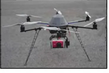
The UAV used in this study is Hexacopter UAV as shown in Figure 1. It has the ability for automatic height control, take-off and landing with autonomous and manual control, provide automatic stabilizer and autonomous way point navigation using M ikroKopter Tool, with GPS antenna, altimeter and magnetometer to calculate the position coordinates during flight.
Figure 1. Hexacopter UAV attached with digital camera Canon PowerShot SX230
HS.
1.3. Digital Camera Calibration M ethod
IOPConf. Series: Earth and Environmental Science 18 (2014) 012030 doi:10.1088/1755-1315/18/1/012030
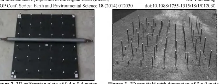
Figure 2. 3D calibration plate o f 0.4 x 0.4 meter. Figure 3. 3D test field with dimension o f 9 x 9 meter.
1.3.1. Laboratory Calibration
A digital camera was setup at different configurations (convergent, generic network and stereo) and different heights at 80cm, 100cm and 120cm. All camera configurations, images o f calibration plate were taken at each position in landscape position o f 0 degree and in portrait position o f 90 degrees. The light rays from the camera station are pointing towards center o f calibration plate. For convergent and stereo configuration, eight (8) images were taken from four (4) stations around the calibration plate while for generic network configuration sixteen (16) images were taken from eight (8) stations around the calibration plate at different height per dataset. After images o f the calibration plate were acquired, these images were downloaded into a computer for data processing and analyzed using photogrammetric calibration software. As standard procedure o f camera calibration, the results comprised of eight (8) camera calibration parameters which include focal length (c), principal point (xp, yp), radial distortions (kj, k2, k3) and tangential distortions (pi, p2).
1.3.2. F ield Calibration
Field camera calibration site is located near the Faculty o f Geoinformation and Real Estate (FGRE), Universiti Teknologi M alaysia (UTM). To develop the field calibration, as mentioned in Section 2.3, the test field area has dimension o f 9 x 9 m and 81 target points. Each target is determined based on close traverse around the test field using a total station for determination o f 3D coordinates. Image acquisition is divided into two parts based on convergent and stereo configuration. For the convergent case, the UAV was flown at the height o f approximately 5 m while for the flying height is stereo 20 m. The UAV was flown manually, due to the test field is near to the building. A total o f 32 images for camera configuration in convergent and 28 images o f the stereo camera configuration were acquired. Eight (8) images per camera configuration were chosen for image processing. The field calibration process was performed similar to laboratory calibration. For future photogrammetric application, the field calibration should be employed so that accurate results could be achieved.
Results and Discussion
In this section, the results o f measurement for different camera configuration setup, camera elevation and different calibration methods which are laboratory calibration and field calibration are briefly discussed. A fter the image processing, camera calibration parameters were obtained from the camera calibration software which utilizes self-calibration bundle adjustment. The results for the different camera setup, different camera elevation and different methods are tabulated in the following sections.
1.4. Camera Configuration Setup versus Camera Elevation
IOPConf. Series: Earth and Environmental Science 18 (2014) 012030 doi:10.1088/1755-1315/18/1/012030
camera configuration for every camera elevation, the photogrammetric calibration software failed to process the image due to weak geometry which means the results depend on the configuration position o f the camera and the angle between the cameras. The smaller the angle, the less will be the accuracy o f the result. On the other hand, for aerial photogrammetry normally height-base ratio A/B, is employed. Based on this configuration, the higher accuracy could be achieved when the intersection angle is near 90° and also other constraints must be considered.
Table 1. Camera calibration parameters for camera configuration setup at 80 cm height.
Camera Configuration Setup at 80cm Elevation Camera
Calibration Parameters
Convergent
(Mean) Std. Dev.
Generic Network
(Mean)
Std. Dev. Stereo
(Mean) Std. Dev. c (mm) 5.104800 0.015185 5.099660 0.005668 Failed Failed xp (mm) -0.039780 0.008704 -0.040620 0.005612 Failed Failed yp (mm) -0.019120 0.011944 -0.023320 0.005497 Failed Failed k1 0.001637 0.000310 0.001795 0.000264 Failed Failed k2 -0.000109 0.000224 -0.000179 0.000390 Failed Failed k3 0.000026 0.000031 0.000030 0.000248 Failed Failed p1 0.000531 0.000115 0.000500 0.000041 Failed Failed p2 0.000559 0.000151 0.000615 0.000065 Failed Failed
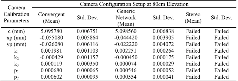
Table 2. Camera calibration parameters for camera configuration setup at 100 cm height.
Camera Configuration Setup at 80cm Elevation Camera
Calibration Parameters
Convergent
(Mean) Std. Dev.
Generic Network (Mean)
Std. Dev. Stereo
(Mean) Std. Dev.
c (mm) 5.095780 0.006751 5.098560 0.006838 Failed Failed xp (mm) -0.055080 0.005864 -0.044420 0.003905 Failed Failed yp (mm) -0.026080 0.006116 -0.022220 0.004072 Failed Failed k1 0.001981 0.001103 0.002251 0.000264 Failed Failed k2 -0.000429 0.001157 -0.000450 0.000175 Failed Failed k3 0.000119 0.000350 0.000074 0.000029 Failed Failed p1 0.000680 0.000065 0.000546 0.000052 Failed Failed p2 0.000602 0.000095 0.000554 0.000041 Failed Failed
The results o f camera calibration which utilizes camera configuration setup at the position o f 100cm height are shown in table 2. In this table, the lowest standard deviation for focal length is ±0.006751mm achieved by the convergent configuration. While for the principal point offset coordinates xp and yp, is ±0.003905mm and ±0.004072mm respectively for generic network configuration. For the remaining results o f camera calibration, the differences in standard deviation are small.
IOPConf. Series: Earth and Environmental Science 18 (2014) 012030 doi:10.1088/1755-1315/18/1/012030 Table 3. Camera calibration parameters for camera configuration setup at 120 cm height.
Camera Configuration Setup at 120 cm Elevation Camera
Calibration Parameters
Convergent
(Mean) Std. Dev.
Generic Network
(Mean)
Std. Dev. Stereo
(Mean) Std. Dev.
c (mm) 5.107440 0.011803 5.104560 0.006694 Failed Failed xp (mm) -0.045920 0.016438 -0.046020 0.011368 Failed Failed yp (mm) -0.008180 0.007599 -0.008960 0.004021 Failed Failed k1 0.002212 0.000430 0.002203 0.000180 Failed Failed k2 -0.000441 0.000280 -0.000581 0.000182 Failed Failed k3 0.000037 0.000113 0.000117 0.000051 Failed Failed p1 0.000580 0.000141 0.000614 0.000111 Failed Failed p2 0.000395 0.000112 0.000404 0.000051 Failed Failed
1.5. Laboratory Calibration versus Field Calibration
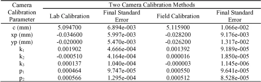
Table 4 shows the camera calibration parameters and final standard error for laboratory calibration and field calibration. The results o f the laboratory calibration and field calibration showed slight different o f total standard error for both methods. Similarly, for radial lens distortion and tangential lens distortion the standard error for both methods showed slight different. Based on the results o f both methods, the field camera calibration method is reliable and useful calibrating non-metric digital camera.
Table 4. Camera calibration parameters for laboratory calibration and field calibration.
Camera Two Camera Calibration Methods Calibration
Parameter Lab Calibration
Final Standard
Error Field Calibration
Final Standard Error c (mm) 5.094700 6.894e-003 5.115900 1.066e-002 xp (mm) -0.034600 5.997e-003 -0.028200 9.176e-003 yp (mm) -0.020000 5.470e-003 -0.026200 1.317e-002 k1 0.001902 4.666e-004 0.001392 9.189e-005 k2 -0.000510 4.164e-004 0.000016 1.850e-005 k3 0.000137 1.040e-004 -0.000003 1.145e-006 p1 0.000464 9.747e-005 0.000550 9.641e-005 p2 0.000566 1.295e-004 0.000512 8.528e-005
Conclusion
In photogrammetric application especially for close range photogrammetry, both convergent and generic network configurations are widely used. In general, it is found that the standard deviation o f focal length improve well as the height increases. For the other camera calibration parameters, the standard deviations are very small, minimum and close to zero value. For generic network configuration, it produces better result compared to convergent configuration with reference to the standard deviation o f focal length as shown in Table 3. The results also showed that as the height o f the camera increases the standard deviation decreases as shown in Table 1, 2 and 3. For stereo configuration, the result showed that this configuration are not suitable for camera calibration.
IOPConf. Series: Earth and Environmental Science 18 (2014) 012030 doi:10.1088/1755-1315/18/1/012030 Acknowledgement
The authors would like to thank Institute o f Geospatial Science & Technology (INSTEG) and Faculty o f Geoinformation and Real Estate, UTM. Also, the authors would like to thank Sustainability Research Alliance UTM for providing the fund to enable this study is carried out.
References
[1] Zhang, Z. 2000. A flexible new technique for camera calibration, IEEE Trans. Pattern Anal. Mach. Intell. 22 (11) pp.
[2] Barazzetti, L., Mussio, L., Remondino, F., Scaioni, M. 2011. Targetless camera calibration, Politecnico di Milano, Dept. o f Building Engineering Science and Technology, Milan, Italy
[3] Brown, D. 1989. A strategy for multi-camera on-the-job self-calibration. Institute for photogrammetry Stuttgart, Festschrift Friedrich Ackermann 60th Birthday www.vision.caitech.edu/bouguetj/calib_doc/papers/Clarke98_calib_history.pdf
[4] Tomas Svoboda, Daniel Martinec, and Tomas Pajdla. 2005. A convenient multi-camera self calibration for virtual environments. PRESENCE: Teleoperators and Virtual Environments, pp 407-422, 14(4), August 2005.
[5] Grammatikopoulos, L., George, K., Petsa, E., Kalisperakis, I. 2007. A unified approach for automatic camera calibration from vanishing points. ISPRS Journal o f Photogrammetry and Remote Sensing, vol. 62, pp. 64-76.
[6] Mendonca, P. R. S., Cipolla, R. 1999. A simple technique for self-calibration. Department o f Engineering University o f Cambridge Trumpington Street, Cambridge, UK, CB2 1PZ. http://mi.eng.cam.ac.uk/~cipolla/publications/inproceedings/1999-CVPR-M endonca-self-calibration.pdf
[7] Mohan, A.S.R.K.V.M, Solanki, S.S., Ramalu, V.S. 2002. On-the-job calibration o f digital camera for industrial photogrammetry. Indian National Cartographic Association. http://incaindia.org/INCA-PDF/vol22/11.pdf
[8] Clarke, T. A., Fryer, J.G. 2003.The development o f camera calibration methods and models. http://www.vision.caltech.edu/bouguetj/calib_doc/papers/DevelopmentCameraCalibration M ethodsM odels.pdf
[9] Moea, D., Sampatha, A., Christophersona, J., Bensonb, M. Self-calibration o f small and medium format digital cameras. ISPRS TC VII Symposium - 100 Years ISPRS, Vienna, Austria, July 5-7, 2010, IAPRS, Vol. XXXVIII, Part 7B.
[10] Fraser, C.S. 1997. Digital camera self-calibration. ISPRS Journal o f Photogrammetry and Remote Sensing Volume 52, Issue 4, August 1997, Pages 149-159.
[11] Udin, W.S., Ahmad, A. 2011. Calibration o f high resolution digital camera using self calibration bundle adjustment method. IEEE 7th International Colloquium on Signal Processing and its Applications.
[12] Linder, W. 2006. Digital Photogrammetry: A Practical Course. ISBN-13 978-540-29152-7 Springer Berlin Heidelberg N ew York.