Abstract – Design by Rule
1
APPLICATION AND EVALUATION OF “DESIGN BY RULE”
PROCEDURES APPLICABLE TO NUCLEAR POWER PLANT ASME B&PVC SECTION III
CLASS 2 AND 3 PIPING
By John D. Stevenson
ABSTRACT
This paper describes a “Design by Rule” procedure that could be used to seismically design nuclear
safety related cold (t
o< 150°F, 66°C) piping. The procedure pre-engineers the location of transverse pipe
supports, which will maintain the piping system within applicable code stress limits which include
seismic design loads.
Commercial nuclear power plants and other nuclear material and waste processing plants typically
contain over 150,000 feet (48,000 meters) of cold safety related piping requiring seismic design. The
engineering effort using conventional stress analysis procedures typically requires over 400,000 man
hours per plant. By use of the “Design by Rule” procedure suggested herein this engineering man hour
effort could be reduced by at least 70 percent with no loss of design conservatism.
The “Design by Rule” procedure consists of locating transverse pipe supports as multiplier of dead
weight support spacings. Typical piping construction codes such as ASME B&PVC Section III,
Subsection NF and ASME B31.1 recommend dead weight support spacings which result in a prescribed
longitudinal dead weight stress in the piping typically defined as around 0.1 S
cwhere S
cis the allowable
stress in the pipe.
By specifying multiples of these dead weight support spacings it is possible to determine the
following:
•
The dominate frequency of the piping of the piping in transverse and vertical directions
•
The resultant seismic force to be applied to the piping taken from the applicable seismic response
spectra
•
The limiting seismic and total longitudinal stress in the piping system as a function of the support
spacings
With this information and the procedure developed in this paper it is possible to demonstrate that a
piping system is within code allowable limits without the effort to prepare an analytical computerized
model of the piping system and to determine the frequency of the piping system.
Abstract – Design by Rule
2
The Application of Design By Rule to the Design of Nuclear Safety Related Piping in Nuclear Facilities
1.0
Introduction
This paper contains a draft of a non-mandatory appendix being proposed as part of the revision of
ASCE-4-1998 Standard, “Seismic Analysis of Safety-Related nuclear Structures and Commentary,” American
Society of Civil Engineers which is due to be published in 2010. This appendix uses simplified analysis
procedures termed the “Load Coefficient Method” consistent with the ASME Boiler and Pressure Vessel
Code, “Section III Pressure Retaining Components in Nuclear Service, Appendix N, Dynamic Analysis,”
developed by the American Society of Mechanical Engineers. A “Design By Rule” procedure is
developed in the Appendix B which makes use of the ratio of transverse to vertical pipe support spacings
which, together with the Load Coefficient Method, can be used to design pipe supports.
Use of this Appendix B could result in a significant reduction of the analytical engineering effort and cost
to design nuclear safety related cold (i.e. T
D<65
⁰
C) piping where T
Dis the design temperature of the
piping as compared to other commonly used analytical procedures such as:
•
Equivalent static
•
Modal analysis
•
Time-history
This Design By Rule procedure is not recommend for elevated temperature piping since the thermal
stresses induced in the piping cannot be controlled using simplified support spacing layout methods
without detailed attention to the location of pipe supports.
2.0 Analysis of Cold Piping
Cold piping typically has been analyzed by the modeling and analysis procedures as described by the
three bullet procedure indicated above. Simplified ASME BPVC Section III, Appendix N, paragraph
1225.1 procedure termed the Load Coefficient Method has been developed, which can be used to analyze
cold piping. The Load Coefficient Method simplified procedure, combined with the Design By Rule
procedure where transverse pipe support spacing is developed as a multiple of design code deadweight
support spacing, is discussed and the application demonstrated in the proposed Appendix B to the
ASCE-4 Standard.
Abstract – Design by Rule
3
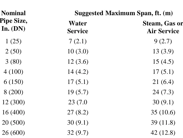
Table 1 Piping Deadweight Support Spacing
l
vSuggested Maximum Span, ft. (m)
Nominal
Pipe Size,
In. (DN)
Service
Water
Steam, Gas or
Air Service
1 (25)
7 (2.1)
9 (2.7)
2 (50)
10 (3.0)
13 (3.9)
3 (80)
12 (3.6)
15 (4.5)
4 (100)
14 (4.2)
17 (5.1)
6 (150)
17 (5.1)
21 (6.4)
8 (200)
19 (5.7)
24 (7.3)
12 (300)
23 (7.0
30 (9.1)
16 (400)
27 (8.2)
35 (10.6)
20 (500)
30 (9.1)
39 (11.8)
26 (600)
32 (9.7)
42 (12.8)
Notes:
1.
Suggested maximum spacing between piping supports for horizontal straight runs of standard
schedule 40 and heavier schedule piping with a maximum operating temperature of 750 °F (400 °C).
2.These spans do not apply where there are concentrated loads between supports such as flanges,
Abstract – Design by Rule
4
Table 2 Piping Fundamental Frequencies, fw and fs, in Hz as a Function of Table 1 Suggested Deadweight
Support Spacing, Based on Simply Supported Single Spans
Weight (lbs) Pipe
Size (Std)
(in.)
Water (ft)
Steam & Air (ft)
Lw
(ft)
Ls
(ft)
Lw3
x106 (in3)
Ls3
x106 (in3)
l (in4)
Ww
(lbs)
Ws
(lbs) fw
(Hz) fs
(Hz)
1 2.053 1.68 7 9 0.593 1.26 0.0874 15.10 14.05 16.70 11.85
2 5.108 3.66 10 13 1.732 3.80 0.666 51.08 47.60 14.85 10.25
3 10.78 7.59 12 15 2.98 5.83 3.02 129.0 114.0 16.23 11.40
4 16.30 10.8 14 17 4.74 8.49 7.23 228.0 183.7 13.80 11.56
6 31.48 19.0 17 21 8.52 16.00 28.14 535.0 399.0 13.30 11.20
8 50.24 28.6 19 24 11.94 23.89 72.5 955.0 686.0 13.50 11.20
12 98.60 49.6 23 30 21.00 46.66 279.3 2270 1,490 12.95 10.70
16 141.68 62.6 27 35 34.05 74.09 562 3820 2,195 11.13 9.95
20 204.60 78.7 30 39 46.60 102.5 1,114 6,140 3,070 10.70 10.15
24 278.48 94.62 32 42 56.70 128.02 1,943 8,930 3,980 10.40 10.40
1. Frequencies determined = 1.57 (EIg/WL3)1/2 from Ref. C5.7 12 (i.e., for pinned-support single span) 2. E = 29 x 106 psi, I = moment of inertia, in; g = accelerations of gravity, 386/in/in2
3. Mmax = 0.107 WL2 for static moment for a uniformly loaded span that is continuous over several supports
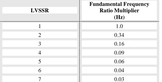
Table 3 Fundamental Pipe Frequencies as a Function of Lateral-to-Recommended Vertical-Support-Span-Ratio (LVSSR),
LVSSR
Fundamental Frequency Ratio Multiplier
(Hz)
1 1.0
2 0.34
3 0.16
4 0.09
5 0.06
6 0.04
7 0.03
Abstract – Design by Rule
5
APPENDIX B Simplified Design of Cold Piping by the Design by Rule and Load Coefficient Methods
B.1 Introduction
Cold piping is defined as having operating temperature, To equal to or less than 150⁰F (56⁰C) or the piping
operates in an environment where the differential temperature between the temperature the piping was installed and the environment surrounding the pipe is less than 100F⁰ (63C⁰).
B.2 Load Coefficient Method
In the application of the Load Coefficient Method, LCM the piping system between transverse supports may be analyzed to determine the dominant frequency response of the piping system. Alternatively, support spans shown in Table 7.5-1 (Table 1) together with Tables 7.5-2 (Table 2) and 7.5-3 (Table 3) can be used to determine the fundamental frequency of the piping system. When multiples of the deadweight support spacing are used transversely to support the pipe it is termed the Design By Rule Method. In determining the spacing for the deadweight supports as well as
transverse and longitudinal supports, the allowable stresses or stress allowance shown herein maybe used when considering design basis seismic loads where:
S = code-allowable normal primary stress[1]
0.20 S = allowance for dead-load bending stress plus vertical seismic-bending stress 0.5 S = allowance for design pressure
membrane stress in the longitudinal direction 2.30 S = allowance for seismic[3]
bending stress (limit state B)[2] 3.0 S = Total allowable stress[3]
Otherwise, use the allowable stress as defined by the specified piping code or standard.
[1]
To meet some piping design codes, it is necessary to define S allowable as Sm allowable stress intensity.
[2]
Limit state B behavior as opposed to limit state A behavior is required to ensure leak-tight integrity.
[3]
This allowable stress assumes that the service level D allowable stress of ASME B&PVC III is applicable.
The seismic loads on the piping system or segments between transverse supports are statically applied as equivalent load along the three orthogonal axes of the pipe. These seismic loads include two horizontal transverse loads perpendicular to the axis of the pipe and a longitudinal load along the axis of the pipe. These loads are determined as K x Sa x M in each
direction where:
K = the load coefficient as defined in Appendix N of the ASME B&PVC Section III(B.1), which range from 0.4 to 1.5 as a function of the ratio of the spectral acceleration at the dominant piping system frequency in the direction of the earthquake, divided by the peak spectral acceleration in that direction times 1.5 Sa = peak spectral acceleration from
applicable response spectrum M = distributed mass of the piping
system
The seismic evaluation procedures contained in this section for cold piping are similar to that recently published in Appendix 31 E to the ASME B31 Code (B.2).
B.3 Design by Rule Method
The transverse support spacings are selected as multiple of the deadweight support spacings shown in Table 7.5–1.
(a) Requirements of support spacings as a function of applicable seismic response spectrum accelerations are categorized as follows:
1. Group A – applicable seismic response spectra acceleration is limited to 0.74g, when the piping transverse support spacing is equal to four times Table 7.5–1 spans.
2. Group B – applicable seismic response spectra acceleration is limited to 1.3g, when the piping transverse support spacing is equal to three times Table 7.5–1 spans.
3. Group C – applicable seismic response spectra acceleration is limited to 2.95g, when the piping transverse support spacing is equal to two times Table 7.5–1 spans.
Abstract – Design by Rule
6
piping transverse support spacing is equal to one times Table 7.5–1 spans.
Where pipe spans contain concentrated weights, the spacings of Table 7.5–1 need to be reduced. In such instances, the concentrated weight shall be multiplied by the reciprocal of the weight per foot of the piping times two:
(Eq. B7.5-1)
where:
L = concentrated weight equivalent length of pipe, ft(m)
Wc = concentrated weight, lbs
(kg/m)
wp = unit weight of pipe, lbs/ft
Longitudinal (axial) pipe support shall be required for runs that equal the limiting Category A, B, C, and D spans times 3 . A longitudinal support may be placed as a transverse support on an adjacent perpendicular pipe segment, within an offset distance from a pipe elbow or tee, not to exceed four times the nominal pipe diameter.
Piping systems containing fittings with stress indices, B2, or stress intensification factors, i, greater than 1.0 require that the limiting Group A, B, C, and D seismic acceleration be divided by the limiting stress intensification or indice factors.
(b) Seismic Anchor Motion
In addition to the seismic inertia requirements determined in Section B.3(a), seismic anchor motion associated with relative seismic-induced vectorial displacement of pipe nozzle or anchor support is limited to ±1.2 in (31 mm). Also, the closest support to the component pipe nozzle is not less than the deadweight support spacing of Table 7.5–1, unless such differential seismic
displacements are explicitly considered in design in the same manner as restraint of free-end
displacement effects or restraint of thermal movements are considered, as prescribed by the applicable piping design code.
(c) Design Temperature, Layout Size, and Material Strength Limitations
5. Seismic design by rule shall not be permitted for piping systems that require a flexibility analysis.
6. Design by rule for piping systems need not be limited by nominal pipe diameters.
The specified minimum ultimate strength of the pipe material is equal to 60 ksi (415 MPa) and specified minimum yield is limited to 35 ksi (240 MPa), when using the limiting
acceleration and displacement values given in Groups A D. For materials with other specified minimum yield and ultimate strengths, the procedure may be used by modifying the spectral acceleration and displacement values in accordance with procedures given in the commentary for this section.
B.4 Cold Piping
The simplified methods of analysis applied to cold piping are usually limited to 6 inches or less nominal-diameter pipe. For piping larger than 6 inches in diameter, while there is no technical limitation to the application of the simplified methods, the engineering design economy of the use of simplified methods tends to be offset by the relative conservatism of the methods as compared to the results of 3D dynamic finite-element modeling response spectrum modal analysis
procedures.
Recommended piping deadweight support spacings are contained in two of the commonly used piping design codes. Table 121.5 of ASME B31.1 and Table NF 3611.1 of ASME B&PVC, Section III, Subsection NF , and referenced in ASME B31.3 as shown in Table 7.5–1 as a means to control deadweight bending stresses in the pipe and the amount of deadweight deflection of the piping between supports. When these span lengths are used in design along with a typical span length tolerance of up to +1.2
l
v, the deadweightstress in the pipe is limited to about 15% of the normal allowable bending stress or stress intensity, S or Sm, in
the pipe, and vertical seismic loading stress resultants are assumed to be limited to 5% of the normal allowable stress.
The fundamental frequency of pin-supported straight-pipe segments using the Table 7.5–1 support spacing is shown in Table 7.5-2.
The transverse lateral restraint or support of the piping may be taken at multiples of the deadweight
)
/
(
2
W
cW
pAbstract – Design by Rule
7
vertical support span lengths. The dynamic dominant frequency characteristic of the piping system is based on transverse lateral horizontal-to-deadweight vertical span ratio multiples of the deadweight support spans for straight-pipe segments, as shown in Table 7.5–3. Localized piping segment geometries between
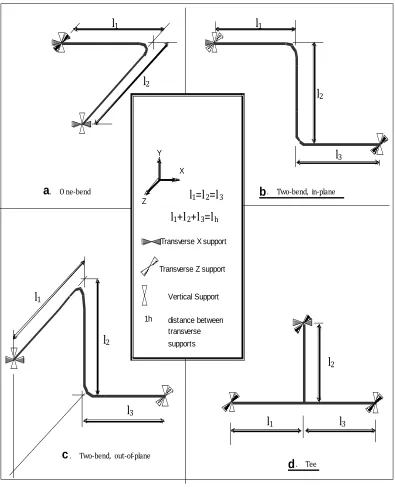
transverse supports for L, Z, or geometries shown in Figure B.1 have similar frequency characteristics to that of straight pipe
B.5 Application of the Seismic Load Coefficient Analysis Method
The LCM can be conservatively used by assuming the dominant mode of the piping system is in resonance with the peak of the applicable response spectrum. This assumption results in a factor of 1.5 applied to the peak of the applicable response spectrum acceleration, as recommended by the U.S. NRC Standard Review Plan (Section 3.7.2). The addition of the 0.5 factor to the spectral multiplier is meant to compensate for higher modes and the effect of static versus dynamic mode shapes applied to a piping system that is continuous over several supports.
For the practical use of the LCM, it is necessary to consider the dynamic characteristics of the piping system, particularly when its fundamental dominant frequency is on the soft side and is significantly displaced from the peak of the applicable response spectrum.
Application of the LCM is described as starting at a pipe anchor or nozzle locate the first transverse support as close to the nozzle or anchor such that any seismic induced displacement of the nozzle or anchor does not exceed 3.0 S stress in the pipe. The value of 1.2 inches vectorial transverse displacement stated in Section B.3(b) assumes the first transverse restraint is one deadweight support spacing from the nozzle measure along this longitudinal axis of the pipe. Ideally the first transverse support should be as close as possible to the nozzle or anchor such that the seismic induced displacement of the anchor or nozzle taken by itself does not result in exceeding a 3.0 S stress limit in the pipe.
After the location of this first transverse support is determined proceed along the longitudinal axis of the pipe to locate the next transverse restraint such that the allowable primary stress limit in the pipe including the seismic inertia load on the pipe from the applicable response spectra does not exceed the piping code allowable stress. Pre-engineered spacing tables and charts are described in Ref. B.4. These tables and charts can be pre-engineered as a function of the
applicable code allowable stresses, pipe material properties and applied equivalent static forces for all combinations of spans lh,, lh = l1 + l2, and lh = l1 + l2 +
l3 where lh is the maximum span between straight spans
of pipe and l1, l2 or l3 are as shown in Figure B.1.
A typical response spectra is shown in Figure B.2. This spectra is typical of an in-structure response spectra at the mid-height of a shear wall-type structure with 4% building damping founded on rock. It should be noted that the use of 4% damping for the building indicates that the walls carrying in-plane shear have not cracked. If the in-plane shear forces in the walls are of such a magnitude that the walls generally have cracked, a more appropriate building damping should be 7%. The out-of-plane direction for concrete walls and slabs are generally assumed cracked in bending.
At 2.38 Hz, the spectra acceleration from Figure B.2 for 5% pipe damping is 0.59g in one of the global x, y, and z directions defined by the response spectrum. This approach would be repeated for the other two global directions. These values would then be multiplied by 1.5 to account for higher modes and in the above direction case, the resultant would be 0.59 x 1.5 = 0.89g. It should be noted that the peak of the 5% damped spectra shown in Figure B.2 is 1.8g. The resultant of 0.89/1.8 = 0.49. As 0.49 exceeds the lower bound of 0.4 from the LCM of the ASME code, use 0.89g as the static seismic load coefficient to be applied to the masses of a static model in the applicable direction.
Having to construct a static finite-element model of the piping system limits the practical use of LCM method if it applied to the whole piping model.
The seismic LCM was defined in Appendix N of the ASME B&PVC Division 1, Appendix N (C7.5 7) with a Kh that varies between 0.4 and 1.5 as a function
of the dominant frequency of the piping system. K equal to 1.0 was used to lay out and design seismically supported piping for the Indian Point Unit 3 Nuclear Power Station (C7.5 13). To demonstrate the adequacy of this method, 53 lines thus laid out and supported were analyzed using finite-element 3D dynamic models subject to in-structure response spectrum modal analysis defined from the site. The highest demand/capacity ratio recorded for the 53 lines dynamically analyzed was 0.90St, with a mean value of
0.35St for the specified maximum allowable total stress,
st, in the piping system for the load combination that
Abstract – Design by Rule
8
A more practical application of the LCM can be developed for typical pipe geometries between transverse supports, such as shown in Figure B.1. Limiting bending moments can be determined by pre-engineering for all combinations of L for straight runs and
! "' , ,
, 1 2 3
2
1andl forelbowsLand l l andl for sandbranch
l
fitting segments for pinned-support boundary conditions. The limiting seismic moments thus determined can then be tabulated as a function of the following:
• Applied spectral acceleration (i.e., 0.5g, 1.0.g, 1.5g, 2.0g, etc.)
• The K factor selected (0.4 to 1.5); the applicable response spectral value multiplied by 1.5
• Pipe nominal diameter (defines deadweight support spacing as shown in Table 7.5–1)
• Pipe material that defines minimum specified yield and ultimate strength values
• Specified design code (defines allowable stresses for the pipe material)
Typical straight-segment lateral support span tables can be developed as a function of these variables and pre-engineered figures applicable to L, Z, and segments to determine the next location of a transverse support, as described in Ref. B.4.
It should be noted that the use of Table 7.5–1 deadweight vertical support spans ensures that resultant stresses in the piping will be relatively independent of pipe diameter and schedule for schedule 40 and larger pipe schedules.
In general, seismic impacts from the same or small size and schedule pipe are assumed not to cause damage to either piping system.
Typical fundamental frequencies for piping with span lengths given in Table 5.7–1 and pin supports are shown in Table 5.7-2. As a function of multiples of lateral-to-vertical-support-span ratios (LVSSR) for straight-line pipe segments, a coefficient given in Table 5.7–3 times the frequency given in Table 7.5–2 determines the frequency of piping systems with LVSSR greater than 1 as a multiple of deadweight support span spacings.
B.6 Application of the Design by Rule Method Procedure for Determining Design by Rule Spectral Accelerations Limits for a Particular LVSSR Value of 1 to 4
B.6.1 Example Problem
The deadweight support spacing results in
deadweight (1.0g) stresses in the piping equal to or less
than 2250 psi, which includes a tolerance on Table 7.5– 1 support spacing of +20%.
The moment in the piping system as a result of horizontal earthquake inertia effects is a function of the distance between lateral or transverse supports. If a value of 4 times deadweight spacing is used for transverse restraints, the resultant stress in the pipe due to a 1.0g transverse static load would be 16 times the deadweight stress: 16 x 2250 = 36,000 psi. Assuming a maximum longitudinal pressure stress is also present, Sp
≤ 0.5S, where S is the normal allowable stress equal to the lesser of 2 Sy/3 or Sw/3.5 using the ASME B&PVC,
Section III, for Class 2 and 3 piping. It is also assumed that a vertical seismic stress is equal to an additional 0.05S stress added to a 0.5S longitudinal pressure stress
Sample Problem:
Assume ASME SA106 Gr. B with Su = 60 Ksi and Sy = 35 Ksi and S = Su/3.5 = 17.143 Ksi. The
maximum stress taken up by deadweight and pressure in ASTM A106 Gr. B pipe would be 2250 psi for deadweight (for deadweight support spacing from Table 5.7–1), plus an allowance of +20% piping span
tolerance, including a 0.05S allowance for vertical seismic load and maximum pressure load of 0.5S:
Sall = 2250 psi + (0.5 + 0.05)
60000/3.5 = 2250 + 17143 x 0.55)
Sall = 2250 + 9429 = 11679 psi
where:
Sall = the longitudinal stress in the
pipe due to other than seismic inertia load
For a 1.0g lateral seismic load, a lateral spacing four times the deadweight spacing would be: 16 x 2250 = 36000 psi
Increase seismic stress by a factor of 1.5 due to modal combination effects (C7.5 13):
1.5 x 36000 = 54000
The stress available to carry seismic load is (3.0 x S) – 11679
where:
S = 17143 psi and 3.0S = 51429
Abstract – Design by Rule
9
!the limiting seismic inertia
spectral acceleration is:39750/54000 = 0.74g
This is the maximum applied inertial seismic spectral acceleration allowed for straight pipe that is continuous over several supports and with a transverse support spacing of four times deadweight spans, including a +1.2 tolerance as defined in Table 7.5–1.
Similarly, for a three times deadweight spacing of transverse supports:
9 x 2250 = 20250 psi
20250 x 1.5 = 30375 psi
39750 / 30375 = 1.31g
Similarly, for a two times deadweight support spacing of transverse supports:
4 x 2250 = 9000 psi
9000 x 1.5 = 13500 psi
39750 / 13500 = 2.94g
Similarly, for a one times deadweight spacing of lateral supports:
1 x 2250 = 2250 psi
2250 x 1.5 = 3375 psi
39750 / 3375 = 11.78g
Secondary stresses due to seismic anchor motion (i.e., seismic displacement of attached nozzle): Fa 1.0 in diameter pipe
1.0 in schedule 40 pipe with deadweight support spacing = 84 in, from Table 7.5–1
Deflection of cantilever pipe due to load at end of pipe PL3/12 EI
1.0 in = P x (84)3 / (12 x 29 x 106 x .0874) = 592704 P / 30.42 x 10⁶
.592704 P / 30.42 1.0 = .01948 P P = 51.33 lbs
M = PL = 51.33 x 84 = 4312 in-lbs s = M/S = 4312 / .1329 = 32446 psi for 1.0 in deflection
Secondary stress allowable = (60000 / 3.5) x 3
Deflection at secondary stress limit: 3S = 51429 / 32446 = 1.6 in
For 8 in diameter pipe
8 in schedule 40 pipe = 19 in = 228 in
1.0 in = P x (228)3 / 12 x 29 x 106 x 72.5 1.0 in = P x 11.852 / 12 x 72.5 x 29 1.0 in = 11.852 / 25230
1.0 in = .000470 = 2128 lbs 2128 x 228 = 485106 in-lbs s = 485106 / 16.81 = 28858 51429 / 28858 = 1.78 in deflection
Try 8 in schedule 80 < = 228 in
1.0 in = P x (228)3 / 12 x 29 x 106 x 105.7 1.0 in = 11852 P / 12 x 29 x 105.7 1.0 in = 11.852 P / 36784
1.0 in = .0003222 = 3104 lbs 3104 x 228 = 707635 in-lbs s = 707635 / 24.52 = 28860 psi 51429 / 28860 = 1.78 in deflection
Assuming an average deflection of 1.6 + 1.78 = 3.38 / 2 = 1.69 inches at the limiting stress of 3S allowable.
Apply a safety margin factor of 1.4 1.69 / 1.4 = 1.21 in
Use a deflection vector limit of 1.2 inches for nozzle displacements due to seismic anchor motion, SAM.
For piping material having specified minimum yield and ultimate stresses other than 35 and 60 Ksi, respectively, the same procedure may be used with appropriate yield and ultimate stress values substituted to obtain corresponding limiting inertial accelerations and SAM displacements.
B.6.2 Application of the Peak Spectral Acceleration of Figure B.2
Abstract – Design by Rule
10
B.6.3 Result of LCM Applied to Design by Rule
Assume the spacing of transverse support is three times deadweight support spacing. From Table 7.5–3, the coefficient associated with the dominant frequency is 0.16. Then 0.16 x 14.85 Hz = 2.38 Hz. The spectral acceleration from Figure B.2 for 5% damping at 2.38 Hz = 0.59g; 0.59g x 1.5 = 0.89g < 1.31g. Therefore, the use of transverse support spacing equal to three times the deadweight spacing is verified.
It should be noted that this seismic design of a cold piping system can be performed without any finite-element modeling of the piping system nor any determination of the actual frequency of the piping system as designed. The application of the LCM and Design By Rule method example presented in this example is valid for straight line piping segments between transverse supports. However, when there are L and sections between supports there will be stress
indice, B2 factors or stress intensification (i)
amplification of stress at the L or section
connections, which must be considered in evaluation capacity versus demand requirements.
B.9 References
B.1 ASME B&PVC Section III, Appendix N, Paragraph N 1225.1
B.2 Stevenson, J.D. (1973). “Seismic design of small diameter pipe and tubing for nuclear power plants.” Paper 314, Fifth World Conference on Earthquake Engineering, Rome.
Abstract – Design by Rule
11
!"#"$%&' ($)"%*+,-"($&. /%0/$-1&23,-&4+/&
25#"6,775&' ($1"8/+/8&9$&:/;/7(#0/$-&()&. #,6"$%&
2,<7/1&,$8&' 3,+-1&)(+&=1/&>"-3&-3/&?(,8&
' (/)"6"/$-&@/-3(8
7A
7
B7
C7C
7
A7C
7B
7A
7B
b
. 2>(D</$8E&"$D#7,$/a
. &F $/D</$8c
. 2>(D</$8E&(*-D()D#7,$/d
. &2//7AG7BG7CH73
7AH7BH7C
Transverse X support
Transverse Z support
Vertical Support X
Z Y
7A
7B
Figure C.7.5.1
distance between transverse supports 1h
Sup