ACTIVE STEERING SYSTEM BASED ON NONLINEAR CONTROL SYSTEM
AHMAD SADHIQIN BIN MOHD ISIRA
A project report submitted in partial fulfilment of the requirements for a award of the degree of
Master of Engineering
(Electrical-Mechatronics and Automatic Control)
Faculty of Electrical Engineering Universiti Teknologi Malaysia
iii
To Universiti Teknikal Malaysia Melaka for supporting my study, To my dearest mother for her encouragement and blessing,
iv
ACKNOWLEDGEMENT
Alhamdullillah, I am grateful to ALLAH SWT on His blessing in completing this project.
I would like to express my gratitude to honourable Associate Professor Dr. Yahaya bin Md. Sam, my supervisor of Master’s project. Under his supervision, many aspects regarding on this project has been explored, and with the knowledge, idea and support received from him, this thesis can be presented within the specified time given.
v
ABSTRACT
vi
ABSTRAK
vii
TABLE OF CONTENTS
CHAPTER SUBJECT PAGE
TITLE i
DECLARATION ii
DEDICATION iii
ACKNOWLEDGEMENT iv
ABSTRACT v
ABSTRAK vi
TABLE OF CONTENTS vii
LIST OF TABLES x
LIST OF FIGURES xi
LIST OF SYMBOLS xiv
LIST OF ABBREVIATIONS xvi
1 INTRODUCTION 1
1.1 Introduction 1
1.2 Project overview 3
1.3 Objective 4
1.4 Scope of the project 5
1.5 Research Methodology 5
1.6 Literature Review 7
viii
2 MATHEMATICAL MODEL SINGLE TRACK CAR MODEL 11
2.1 Introduction 11
2.2 Mathematical modelling of single track model 12 2.3 Linearization for constant velocity and small angle 17 2.4 Disturbance profile 21
2.4.1 Disturbance profile 1 22 2.4.2 Disturbance profile 2 23
2.5 Conclusion 24
3 CONTROLLER DESIGN 25
3.1 Introduction 25
3.2 Overview on sliding mode control 26 3.2.1 Sliding mode control design 26
3.2.2 Switching surface design 28 3.2.3 Stability of sliding mode control 30
3.2.4 Controller design 32
3.3 Linear Quadratic Regulator (LQR) Controller 35
3.4 Conclusion 36
4 SIMULATION 37
4.1 Introduction 37
4.2 Result and discussion 38
4.2.1 Comparison between linear and nonlinear system
model 39
ix
4.2.3 Performance of Active Steering with Different
Disturbance profiles 42 4.2.4 The control input of sliding mode controller 48 4.2.5 Effect of Sigma (σ) Sliding Mode Controller
(SMC) 51
4.3 Conclusion 53
6 CONCLUSION & FUTURE WORKS 54
6.1 Conclusion 54
6.2 Recommendation for future work 55
x
LIST OF TABLES
TABLE NO. TITLE PAGE
2.1 Parameter value for the active steering car system
(BMW 735i) 21
xi
LIST OF FIGURES
FIGURE NO. TITLE PAGE
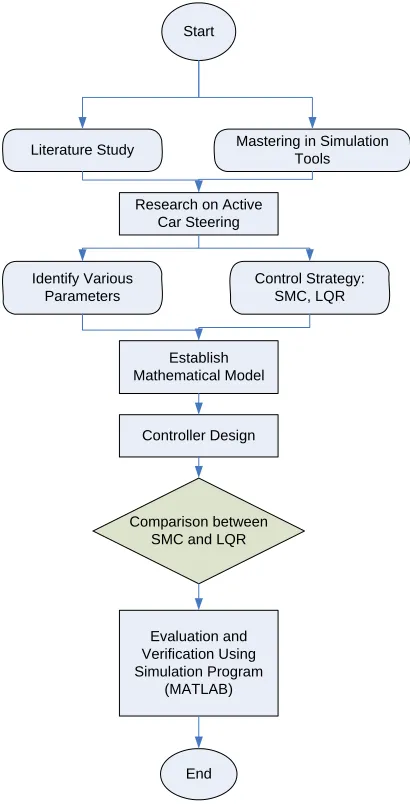
1.1 Research methodology flow chart 6
2.1 Vehicle axis system 12
2.2 Feedback controlled additive steering angle δC 13
2.3 Single-track model for car steering 13
2.4 Lateral forces FytF at the front wheel in tire coordinates and FyF in chassis coordinates 15
2.5 Sidewind disturbance profile 22
2.6 µ-split braking torque disturbance profile 23
4.1 Comparison between linear and nonlinear system
(yaw rate) 39
4.2 Comparison between linear and nonlinear system
(side slip angle) 40
4.3 Comparison between linear and nonlinear system
xii
4.4 Comparison between linear and nonlinear system
(side slip angle). 41
4.5 Comparison between all controllers (sidewind
on yaw rate) 43
4.6 Comparison between all controllers (sidewind on
side slip angle) 43
4.7 Comparison between all controllers (breaking torque
on yaw rate) 44
4.8 Comparison between all controllers (breaking torque
on side slip angle) 44
4.9 Comparison between all controllers (sidewind on
yaw rate) 45
4.10 Comparison between all controllers (sidewind on
side slip angle) 46
4.11 Comparison between all controllers (breaking torque
on yaw rate) 46
4.12 Comparison between all controllers (breaking torque
on side slip angle) 47
4.13 Control input 1 and control input 2 (sidewind at μ=1) 48
4.14 Control input 1 and control input 2 (sidewind at μ=0.5) 49
4.15 Control input 1 and control input 2 (breaking torque
xiii
4.16 Control input 1 and control input 2 (breaking torque
at μ=0.5) 50
4.17 Control sigma 1 and control sigma 2 (sidewind μ=1) 51
4.18 Control sigma 1 and control sigma 2 (side wind μ=0.5) 51
4.19 Control sigma 1 and control sigma 2 (breaking torque
at μ=1) 52
4.20 Control sigma 1 and control sigma 2 (breaking torque
xiv
LIST OF SYMBOLS
F
α - Slide slip angle at front tire
R
α - Slide slip angle at rear tire
F
β - Front chassis side slip angle
R
β - Rear chassis side slip angle
F
c - Front cornering stiffness
R
c - Rear cornering stiffness
F
δ - Front steering angle
R
δ - Rear steering angle
ytF
F - Lateral force at front tire
ytR
F - Lateral force at rear tire
F
A - Distance between center of gravity (CG) and front axle
R
A - Distance between center of gravity (CG) and rear axle
y F
F - Dominant component in chassis coordinates for front tire
yR
F - Dominant component in chassis coordinates for rear tire
X
F - Longitudinal force component
J - Car body moment of inertia
xv
v - Velocity of the car
ZD
M - Disturbance
μ - Coefficient of road friction
( )t
σ - Sliding surface for a single track model Hf - Friction force between ground and the wheel
ρ - Sliding gain for a single track model
δ - Boundary layer thickness for a single track model
β - Side slip angle
r - Yaw rate
xvi
LIST OF ABBREVIATIONS
DOF - Degree of Freedom
ZOH - Zero Order Hold
LQR - Linear Quadratic Regulator
VSC - Variable Structure Control
SMC - Sliding Mode Control
MRAC - Model Reference Adaptive Control
CHAPTER 1
INTRODUCTION
1.1 Introduction
Automatic steering of vehicles is of increasing interest as part of an integrated system of automated highway or drive assistance. The design of active steering control is appeared as robustness problem. A vehicle will face a large variation of its speed and mass of the wind speed and of the contact between the tire and the road surface. Numerous control laws have been designed for automatic steering control. Recently, there are a lot of researches in the area of vehicle stability in sequence to the increasing of vehicle capabilities. This includes the active suspension system and active steering system.
In order to help the driver to maintain a safe drive and comfort, it is important that a good stability control system included into a vehicle. However, it is well known that a driver is slow to react when the vehicle becomes unstable. This is where the automatic driver assistance system takes place whereby; whenever a driver loses some degree of control, the system will detect and stabilize the vehicle immediately hence enables the driver to regain the control of the vehicle.
2
includes the active steering control system. There are several controller techniques proposed to achieve a good vehicle stability system (Ackermann et all, 1995). The techniques are used to overcome several basic problems associated with vehicle handling which prevents vehicle stabilization and the movement of the vehicle towards the desired path (Nur, 2006).
The most common factors that influence the vehicle stability are vehicle handling and ride characteristics. The combination of these two factors with the mechanics of the road-tire interaction contributes to this problem. Therefore, the suitable control system will consider how to overcome the problems stated above.
3
1.2 Project Overview
According to Ackermann (2002), there are already driver assistant systems that use braking method at each wheel. They are cheap due to the reason where they used the hardware of the existing ABS braking system with an additional yaw rate sensor and do not need a new actuator. However, there are several reasons why active steering system is considered as a good alternative.
Firstly, torque is needed to compensate yaw disturbance torques (torque is tire force times lever arm). Secondly, the difference of friction coefficient on the left and right sides (μ-split braking) may be the cause of the disturbance torque. A steering torque can compensate the braking torque and enable a straight short braking path. Lastly, energy conservation, reduction of tire wear and brakes and smooth operation around zero correction are the other reasons why an active steering should a good alternative.
In practical situations, active steering is the only feasible way for continuous operation and better comfort under continuous disturbances. Braking systems are not capable of reacting to an emergency situation sufficiently and safely. It cannot immediately compensate small errors and late during intervention of emergency situation when the vehicle is close to skidding or rolling.
The vehicle dynamics are subjected to various uncertainties due to modelling inaccuracies (You et all, 2004). Hence, robust performance capabilities against uncertainties have long been there in the stage for robust controller application due to the limitation of the conventional linear control.
The main objective is to rectify and clarify the automatic control of passenger cars for general lane-following manoeuvres. The 2-DOF controller is based on H∞loop-shaping methodology where it provides good lane-keeping
4
explicit knowledge of the vehicle uncertainty. However, the test results demonstrate the higher the speed of the vehicle the more unstable it will be.
1.3 Objective
There are three main objectives of this study:
1. To develop and establish a single-track car model.
2. To design a controller that based on the robust control strategy (Sliding Mode Control (SMC)). This will overcome uncertainties and disturbances of a road handling.
3. To evaluate and analyzed the performance of the system in time domain related to such as overshoot, rise time and settling time due to step response based on proposed controller.
The main objective on this research is emphasized more on the performance for disturbance rejection to prevent a car skidding due to the disturbances. Thus, various parameters such as tire slip angle and yaw will be observed to verify the performance of the proposed controller. Hence, the performance of the proposed controller will be compared to Linear Quadratic Regulator (LQR).
5
1.4 Scope of Project
The works commenced within the duration of this project are limited to the following aspects:
• It is based on the work done are according to the model developed by Ackermann J. et all, (1995).
• Active car steering system is evaluated on straight road due to various disturbance profiles and coefficient of road friction.
• To design a controller for a single track car model using SMC and LQR technique to compensate disturbances.
• To perform a simulation using MATLAB/SIMULINK to observe the effectiveness and robustness of the controller.
• To compare the performance of the proposed SMC with LQR.
1.5 Research Methodology
The proposal will commence with the literature study in sequence to the learning and mastering the simulation tools ready made in MATLAB.
6
Then, the mathematical model of the controller is developed and this will contribute to the design stage later. At the design stage, a new controller or an enhanced type will be developed. Soon after the design of the required controller is finished, it will be compared to the existed controller in terms of several crucial conditions such as wind, and wet road. In the end, the comparison above is realized using simulation program (MATLAB) to prove its validity.
The methodology of this research is shown in the flow chart in Figure 5 below:-
Start
Literature Study Mastering in Simulation Tools
Research on Active Car Steering
Identify Various Parameters
Control Strategy: SMC, LQR
Establish Mathematical Model
Controller Design
Comparison between SMC and LQR
Evaluation and Verification Using Simulation Program
(MATLAB)
End
7
1.6 Literature Review
Various control strategies have been proposed by researchers to improve the vehicle stability according to several parameter variations of the vehicle. These control strategies are grouped into different approaches and techniques. Thus, several reports will be briefly discussed and presented.
According to W.Sienal (1997), whenever a controller is inserted into a vehicle system, it may worsen the condition of the road handling since most approaches assumed linearized models in the design and do not consider nonlinearity in the tire characteristics. These approaches may yield good results as long as the vehicle remains within the linear region of the tire characteristics. Therefore the condition may worsen the driving situation drastically compared to conventional vehicle, as soon as it enters the nonlinear region of the tire characteristics. It is an important factor to consider the stability of the vehicle when designing a controller.
J. Ackermann (1994) presented a robust decoupling of car steering dynamics with arbitrary mass distribution. The restrictive mass distribution assumption was abandoned and a generalized decoupling control law for arbitrary mass distribution was derived. The result of this paper provides an interface between the modelling of the steering dynamics of a single car by two masses and the higher level control problems of automatic steering and distance keeping of single mass models in a platoon of cars. However, there are some restrictive assumption in this paper which is the constant velocity, small sideslip and steering angles.
Said, (1996) proposed H∞ control strategy for the active steering of railway
8
variations occur, in particular at the wheel-rail interface. The controller is also robust against uncertainties that are not included in the model such as actuator dynamics. The major task was to try and solve the difficult design conflict between the stability, curving performance and passenger comfort requirements. However, studies from this paper shown that the two wheels on the same axle were allowed to rotate independently from each other. The main drawback was; the independently rotating wheel set (or wheel pair) does not have the natural curving ability of the conventional wheel set, and some form of guidance action becomes necessary.
Doyle et al. (1989) proposed H∞ control approach to overcome robust
stabilization and uncertain plants. You and Jeong et al. (2002) designed linear matrix inequalities based on H∞ methodology. Previously H∞ loop-shaping design
procedure was proposed by McFarlene and Glover (1990). The results showed that this method provides a computationally efficient algorithm and does not require explicit knowledge of the uncertainty.
The combinations of H∞ loop shaping and 2-DOF has been reported by You and Jeong (2004) in order to achieve high performance control system for vehicle handling. It has shown that this algorithm allowed separate processing of the robust stabilization problem and reference signals. The test results the robust control scheme offers a computationally efficient method and does not require explicit knowledge of the vehicle uncertainty. The presented system exhibits the required performances and robustness properties under parameter variations while maintaining passenger comfort. However, the test results demonstrate that higher vehicle speed has a destabilizing effect on the vehicle system.
9
nonlinear relationships between the slip angles and the lateral forces on tires, and the uncertainties on the friction of the road surface.
Moreover, intelligent based techniques such as fuzzy logic, neural network and genetic algorithm have been applied to the active steering system. M.K.Park et al. (1996) presented a fuzzy-rule-based cornering force estimator to avoid using an uncertain highly nonlinear expression, and neural network compensator is additionally utilized for the estimator to correctly find cornering force. The result indicated that the proposed control system is robust against the uncertainty in vehicle dynamic model disturbances such as a side wind gust and road conditions.
K.Huh et al. (1999) proposed a fuzzy logic controller with Hardware-In-the-Loop Simulation (HILS) simulator to evaluate the performance of the system on a slippery road. HILS simulator is composed of hardware (steering wheel) and software (vehicle simulation tool and steering control system). This method used fuzzification, fuzzy inference and defuzzification technique. It can be observed that this controller is able to maintain the steering manoeuvrability on slippery road and quite useful in order to correct the vehicle’s route when the vehicle’s direction is biased due to side wind or obstacles. However, the proposed steering control system is similar as the ABS braking system.
1.7 Layout of Thesis
This section explains the outline structure of the thesis.
10
the beginning, the state space representations of the chassis and wheel dynamics comprising of DC motors are formulated. The assumptions and limitations that been added to the model will be described accordingly.
Chapter 3 discusses control algorithm design for controlling the system. The analysis regarding the performance of designed controller will be presented.
Chapter 4 discusses the simulation results. The performance of the SMC and LQR controller are evaluated and analysed by simulation using Matlab/Simulink platform.