ANALYSIS BASED MODIFICATION IN SEQUENCE OF MODERATOR
DUMPING TO ABATE WATER HAMMER.
Raj Kumar Singh and A.Rama Rao Reactor Engineering Division Bhabha Atomic Research Centre Mumbai-400085, India
ABSTRACT
Flow related incidents of shock and vibration are common in various power industries. Among them, transients like water hammer have severe consequence in the connected systems. Water hammer occurs as a result of fast closing/opening of valves and sub-cooled water flowing in pipes or other containers filled with steam or steam-water mixture. As a part of commissioning activity in one of the older generation PHWR, a detail vibration analysis was carried out on the extension of sparger tubes in the reactor at different rates of moderator flow through the sparger. In these reactors, the moderator is dumped into dump tank for reactor shut down. During the dumping trials, high impulsive noise and vibration was observed on the piping and on the sparger. A numerical modeling was also done to understand the under laying phenomena. Modification to the process of moderator dumping was suggested, which was successful in abating water hammer.
INRODUCTION
Recently, three spargers were introduced in one of the older generation PHWR. Through these perforated tubes, heavy water moderator is filled in the calandria. Each sparger is capable of discharging one third of the required moderator flow into the calandria. The total flow from the permissible moderator temperature limit (70C) point of view is 16.5KLPM. The sparger tubes are perforated with different sizes of holes to achieve axial distribution of flow emanating from the sparger. The flow distribution is proportional to the axial distribution of heat generated in the moderator. A flow-adjusting device called whirler has been installed at the inlet to the sparger.
As a part of commissioning activity, a detail vibration analysis was carried out on the extension of sparger tubes. During the dumping trials, high impulsive noise and vibration was observed on the piping and on the sparger. From the signal analysis, the source of high noise & vibration was identified as caused by water hammer on account of sudden conversion of kinetic energy to pressure energy in closing the control valve against large flow.
Sometimes water hammer can be very harmful for the piping of the system. Nuclear regulatory commission has sponsored several studies on water hammer [1]. Systematic analyses of water hammer in some nuclear plants have been carried out [2].Strong dynamic stresses are induced in the walls due to water hammer in closed systems and equipments. Details related to modeling of these stresses can be found in [3] & [4] As water hammer is a system phenomenon, lot of mass and energy interaction takes place in various components in the system. At times it is very difficult to pin point direct cause of water hammer and propagation of the transient effect to other components [5].
The transient event was modeled by numerical model based on finite difference method, which was able to bring out the physics involved in the phenomenon. Sometimes water hammer in single phase system reduces fluid pressure below saturation pressure that leads to temporary voiding. Such cases cannot be modeled with single-phase models. Detailed two-phase models without phase equilibrium assumptions are very complex and computationally expensive. Numerical model discussed here is capable of modeling two phase adiabatic homogeneous fluid in pipes. This approach tries to fills the gap between single phase model and complete two-phase models.
After understanding the behavior of the transient process, the sequence of dumping was modified, that resulted in abating the noise and vibration in the system. Dumping trials were repeated to test effectiveness of modified scheme. The modified scheme was able to effectively contribute towards successful rehabilitation of the reactor.
VIBRATION MEASUREMENT OF MODERATOR PIPING
Vibration was measured on moderator piping during the moderator dumping process. After filling the calandria up to 97.2% level, moderator was dumped in the normal way. The dumping caused high intensity sound accompanied by visibly high amplitude oscillation of the piping. The vibration equipments used for recording the event registered instantaneous overload.
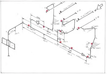
The dumping signal was re-recorded with appropriate measuring equipments. Figure 1 shows the line diagram of piping in the fuelling machine vault. The positions of vibration sensors are shown in the figure. Sensors were also mounted on the end fitting of channel T09 and T10. The high amplitude signal corresponds to closure of Control Valves 58/59. The extended insert experiences more than 25g peak for a short duration of about 100 m sec. Similar levels of amplitude are seen on the extended inserts of sparger S05 and S16.
Fig. 1: Vault Piping Layout and Locations of Accelerometer
clearly seen that the transient signal appears first on pipe near the penetration. The time gap of the signal between sparger and 8” piping signal is clearly seen in the graph indicating that the transient originates from the upstream and not from the calandria/sparger end.
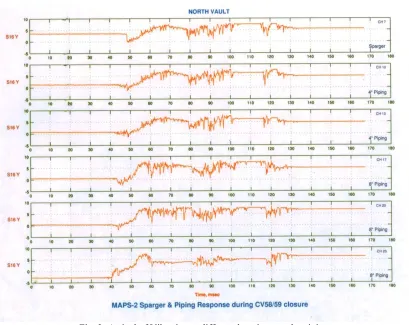
Fig. 2: Arrival of Vibration at different locations on the piping
Figure 3 shows the acceleration time signal during steady state 4 pump operation and during moderator dumping. Control Valves were fully closed in about one second in the test.
Fig. 3: Sequence and timing of Pump trip and CV closure during Moderator Dumping
Vibration measurement during controlled closure of CV 58 & 59:
In the earlier arrangement, the CVs were made to close in about 1.0 second against a flow of nearly 16 to 18 KLPM. Such a sudden closure was resulting in high amplitude acoustic waves traveling in the piping. After a thorough review, it was decided to modify the closing time of CVs. For this, the following scheme was suggested. 1. Dump the moderator
3. After 3 sec. of pump trip, give the signal for CVs closure and Close CVs fully in next 4 seconds.
This scheme was suggested to ensure that the CVs close nearly after 7 seconds after pump trip so that they close against low flow and slowly.
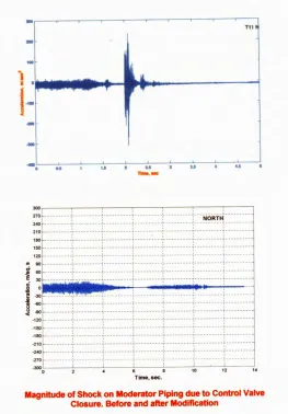
During one of the poison shut down in MAPS-2, measurements were repeated on the extended inserts and piping during dumping under modified scheme for CV closing. Figure 4 shows the vibration signals during dumping. It can be seen that the amplitude of signal corresponding to CV closure has reduced by 25 times. In the FM vault, there was no noise heard on closing the CVs.
Fig. 4: Comparison of Vibration Amplitude before and after Modification in the logic.
NUMERICAL MODELING
Equations for one dimensional homogeneous two phase flow can be written as Continuity equation
x f x g
u u
0
..(1)
t
x
x
1
here
(1
)v
v
αx is the vapor quality
u
u
p
f
(
u
)
u u 0
..(2)
t
x
x 2D
ρ is based on the vapor quality as in equation 1. In case of single phase αx is zero. Otherwise it is between zero and
one. Equation of state is given by
p g( )
..(3)
For given temperature of fluid when density drops below density at saturation pressure, phase transition takes place. Since system is considered adiabatic so energy equation is not needed and so equation 1, 2, 3 are sufficient to solve the system.
Eliminating p from equation 3 and equation 2 and getting equation 4.
u
u
f
(
u
) g'( )
u u 0
..(4)
t
x
x 2D
Multiplying equation 4 with α and adding it to equation 1
u
u
f
(
( g'( ) u)
)
(
( u 1)
)
u u 0
..(5)
t
x
t
x
2D
Let
dx
g'( ) u
u 1
..(6)
dt
It gives two values of α as1
..(7)
g'( )
g '
represents velocity of sound in the fluid medium.
Again using equations 6, 7 and 5 equations 8, 9 and 10, 11 are obtained as below For positive sign of α
dx u g'( )
..(8)
dt
g' d
u f u u 0
..(9)
dt
x 2D
Equation 8 represents characteristic line along which ordinary differential equation 9 must be satisfied. Similarly For negative sign of α
dx u g'( )
..(10)
dt
g' d
u f u u 0
..(11)
dt
x 2D
Equation 10 represents characteristic line along which equation 11 must be satisfied. Detail discussion on derivation of characteristic equation can found in [6].
Equations were discretized in implicit manner. Solution at (n+1)th time step is calculated from nth time step.
present adjacent to closed valve condenses, which causes the pressure to peak. This induced depressurization causes cavitation water hammer.
While in case of moderator dumping with modified scheme, valve was closed 7 seconds after tripping the pump. It was found by analysis that moderator remains in single phase all through and there is no water hammer.
CONCLUSION
As a part of commissioning activity, a detail vibration analysis was carried out on the extension of sparger tubes in the reactor at different rates of moderator flow through the sparger. During the dumping trials, high impulsive noise and vibration was observed on the piping and on the sparger. From the signal analysis, the source of high noise & vibration was identified and remedy was suggested. A numerical model was used to analyze the phenomena. It was verified experimentally that suggested modifications were able to prevent water hammer.
REFERENCES
[1]. Water Hammer in Nuclear Power Plants, NUREG-0582, US Nuclear Regulatory Commission (July 1979).
[2]. Hemmat H. Safwat, Asif H. Arastu and Syed M. Husaini (1990), Systematic methodology for diagnosis of water hammer in LWR power plants. Nuclear Engineering and Design 122, 365-376
[3]. A.S. Tijsseling (2007), Water hammer with fluid–structure interaction in thick-walled pipes, Computers and Structures 85, 844–85.
[4]. Jayaraj Kochupillai, N. Ganesan, Chandramouli Padmanabhan (2005), A new finite element formulation based on the velocity of flow for water hammer problems, International Journal of Pressure Vessels and Piping 82, 1–14.
[5]. R.K. Singh, S.K. Sinha, A.Rama Rao (2010), Study of incident water hammer in an engineering loop under two-phase flow experiment, Nuclear Engineering and Design 240, 1967–1974