Optimum Patch Selection Using GA in Exemplar
Based Image In-painting
Seema Kumari Singh, Prof J.V Shinde
Department of Computer Engineering, Savitribai Phule Pune University Late G. N. Sapkal College of Engineering, Nasik, India.
Abstract— Image in-painting is the art of restoring lost and
selected parts of an image based on the background information in such a way so that the change is not observed by the observer. Image In-painting is very important and emerging field of research in image processing. Image In-painting algorithm have numerous applications such as rebuilding of damaged photographs & films, heritage preservation, removal of superimposed text, removal/replacement of unwanted objects, red eye correction, image coding etc.. In this paper, we are using GA based patch selection approach for Exemplar based Image in-painting using Multiscale graph-cut. In order to improve the computational time and also the acceptable quality of the image, Genetic algorithm is proposed here. Graph cut algorithm is used to solve the problem of energy minimization. Our experiments show how well the proposed algorithm performs compared with the other recent algorithms.
Keywords— Image in-painting, graph-cut, Genetic Algorithm,
Exemplar, Gradient, mutation.
I. INTRODUCTION
Image in-painting is a hot spot in computer graphics and an active area in research in image processing. Image in-painting is also known as image disocclusion or completion. Object removal from images is an image manipulation technique that has a long history. The purpose of removing objects varies from remove undesired object to improve the quality of the image, to airbrushing out political enemies from portraits of important events. Modern photographical manipulations, such as red eye removal from pictures, also utilized this technique. The process of removing objects from images starts with mask out the undesired object, making the area where the object previously occupies a gap. Then the gap will be filled using graphical techniques such as in-painting. The main goal of this process is to fill the missing region/restoring lost part of an image based on the background information. And this process reconstruct image in such a way so that the change cannot be noticeable by an observer.
Image in-painting technique is used in so many fields like preservation of heritage films and television and for special effects production. It is used to restore old/damaged photographs, object removal from an image without affecting the image, image coding [3], [4] and transmission [5] (recovery of the missing blocks) etc.
Following are the Mostly used in-painting methods:- 1. Geometry-based method
2. Exemplar-based method
We can also call Geometry based methods as structure in-painting methods. In this method missing region is filled by
diffusing the image information from the known region into the missing region at the pixel level. This type of algorithm is basically based on PDE (partial differential equation). Geometry-based in-painting methods shows good result in propagating smooth level line or gradients or filling the non-textured target region. This method is generally used when the inpainted region is small. The drawback of this method is, it introduces blurring artifacts in textured or when filling large missing region. The second category is exemplar-base in-painting algorithm. It provide an efficient approach for reconstructing large target regions. Basically it consists of two main steps: The first step is of priority assignment and the second steps consists of selection of best matching exemplar and update all the priorities. Exemplar based in-painting iteratively synthesizes the target region, by the most similar patch in source region. They provide good results in recovering textures or repetitive patterns. This algorithm overcomes the drawback of PDE based in-painting.
In this paper, we are using Genetic Algorithm also categorized as Global search. It is used in computing to find approximate solutions to optimization and search problems. Genetic algorithms are a particular class of evolutionary algorithms that use techniques inspired by evolutionary biology such as inheritance, mutation, selection, and crossover (also called recombination).But we are not using crossover in our algorithm.
This paper is organized as follows: Section II describes the Brief History of exemplar based image in-painting using multiscale graph cut algorithm. Section III describes the implementation details, block diagram of the proposed system. Section IV describes Exemplar based Image In-painting. Section V describes Genetic Algorithm. Section VI gives the results. In section VII we summarized the conclusion of the paper.
II. LITERATURE SURVEY
So many methods have been proposed for image in-painting so far and we can classify them into several categories as follows:
1. PDE based image in-painting 2. Exemplar based image in-painting 3. Texture synthesis based image in-painting 4. Hybrid In-painting.
5. Semi-automatic and Fast In-painting.
in-painting. Exemplar based Texture synthesis modulated by a scheme for determining the fill order of the target region. They used patch based filling approach .Pixels maintain a confidence value. They fill the hole of the target region according to the priority order & this order is determined by the strength of the incoming edges and a confidence value. This technique is capable of propagating linear structures. The limitation in this paper is that the algorithm is not designed to handle curved structures and also they do not handle depth ambiguities.
Bertalmio, Vese, Sapiro ,Osher [12] proposed an algorithm for the simultaneous filling of texture and structure in regions of missing part of the image. They decompose the two image into structure and texture components respectively & perform in-painting separately on them. The result is the combination of these two methods.
Sun,Yuan,Jia,Shum [14] proposed a technique of structure propagation. They first propagate the structure and after structure propagation, they fill the remaining unknown regions using a patch based texture synthesis. In this approach, the user manually specifies the curves, the most salient missing structures.
Jia and Tang [15] proposed a two step method: First a texture based segmentation on the input image and extrapolating the boundary regions by tensor voting to generate a complete image segmentation and second by using tensor voting missing colors are synthesized. Tensor voting method is good for maintaining curvature, but cannot perform well on complex structures and image segmentation of natural images is also a difficult task to perform.
Most of the above exemplar-based approaches are a greedy procedure that means each target pixel is visited only once, and the results are based on the order in which pixels processed.
There are some approaches [16]-[20] formulate image in-painting as a discrete global optimization problem, where the images is modeled using a Markov Random Field (MRF) with pair-wise interactions.
In [16], the objective function is minimized using belief propagation .In [17], [21] for texture synthesis and image completion, Expectation-maximization(EM) schemes are used.
For combining the main features of geometry and exemplar-based in-painting methods Variational models are most appropriate. In [22], the author proposed total variation regularization of the of the correspondence map formulation where the in-painting problem in written in terms of correspondence map. But the author did not study this model numerically.
Arias,Caselles,Sapiro[19],[20], proposed a variational framework for Non-local image in-painting that allows to include features of geometry based approaches by a proper choice based on similarity criterion. Their energy is written in terms of correspondence map and the unknown part of the image. By using Nearest Neighbour Field (NNF) the computational complexity is reduced [24].
Several new algorithms based on Graph cuts have been developed to solve energy minimization problems. In [27]
they give a characterization of the energy functions that can be minimized by graph cuts their results are limited to functions of binary variables.
In [28] the author focuses on geometric rearrangement of images such as image retargeting, in-painting or object rearrangement and these operations can be characterized by a shift-map. The author describes a new representation of these operations as a optimal graph labeling, where the shift map represents the selected label for each output pixel. Data term and a Smoothness term is the two terms which are used in computing the optical shift map. And by using graph – cuts the graph labeling problem can be solved since the optimization is global and discrete.
III. IMPLEMENTATION DETAILS
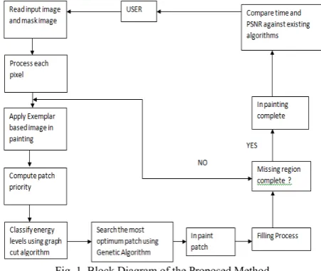
In this paper, we are using GA for patch selection for exemplar based image-in-painting using Multiscale Graph cuts. In order to improve the computational time and also the acceptable quality of the image, Genetic algorithm is proposed here. We also propose a Multiscale Graph cuts algorithm for efficiently solve the energy minimization problem. The Block Diagram of our Proposed method is shown in Fig 1.
Fig .1 Block Diagram of the Proposed Method
The image is provided as an input and also mask image is provided in which the user specify the region which is to be in-painted.
Pixel Mapping of Mask image is done.
After that we apply image in-painting algorithm i.e Exemplar based.
Classify energy levels using Multiscale graph cut.
As we proceeds in exemplar algorithm there is a step of patch selection and for optimum patch selection .We are using GA to find out the optimal patch among all.
Filling process is done.
After that we check whether the complete image is removed or not. If yes we proceed further and if the answer is no, we again apply the Exemplar algorithm.
IV. EXEMPLAR BASED IMAGE INPAINTING Let us first describe the basic terminologies used in in-painting:
Image is represented as ‘I’.
The target region or the region to be in-painted is represented by omega’ Ω ‘.
Source region (I-Ω) that is the region which is not to be in-painted and from where the information is extracted to fill the target region is represented by ɸ.
Boundary of the target region is represented by: δΩ It is an important class of in-painting algorithms. It overcomes the drawback of PDE based in-painting and it is used for reconstructing large target regions. Basically it consists of two basic steps: priority assignment is the first step and the second step consists of the selection of the best matching patch. The exemplar based approach samples the best matching patches from the known region and pastes into the target patches in the missing region. According to the filling order, the method fills structures in the missing regions using spatial information of neighboring regions. Generally, an exemplar-based In-painting algorithm includes the following four main steps:
1. Initializing the Target Region in which the initial missing areas are extracted and represented with appropriate data structures.
2. Computing Filling Priorities: in this a predefined priority function is used to compute the filling order for all unfilled pixels p∈δΩ in the beginning of filling iteration.
3. Searching Example and Compositing: in which the most similar example is searched from the source region Φ to compose the given patch, say Ψ (of size N × N pixels)that centered on the given pixel p . 4. Updating Image Information, in which the boundary
δΩ of the target region Ω and the required information for computing filling priorities are updated.
The input to this algorithm is the original image and the mask image with the target region marked in green color.The very first step is to initialize confidence values. Each pixel maintains a confidence value in our algorithm. We initialize confidence value in the source region to be 1 and 0 in the target region. Next step is to find the boundary of the target region. We construct a Boolean matrix where we put 1’s in the target region and 0’s at other places. After that we calculate patch priorities .For a patch centered at a point p δΩ and its priority can be defined by the product of two terms C(p) and D(p) where C(p) is the confidence term for the patch and the D(p) is the data term for the patch.
P(p)=C(p)*D(p) (1)
Numerical multiplication is very sensitive to extreme values. The priority function needs to be modified in order to achieve good results .So instead of multiplicative priority term we use the additive term.
P(p)=C(p)+D(p) (2)
And also instead of original confidence term we use regularized confidence term.
Another improvement in the priority term by adding weights on the confidence term and the data term.The next step is to find the patch that best matches with the selected
patch Mean square error can be used to do this but it’s a time consuming process so we search only the surrounding portions of the image from a rectangle.
After finding the best exemplar the next step is to replace the patch with the best exemplar and after replacing the patch update the confidence values as follows:
C(p) = C(q) where C(q) represents the confidence term of the patch with maximum priority.
It may happen two or more patches have the same MSE Dealing with such situations with the help of variance and mean we can select the patch. The whole process is continued until all the pixels in the target region is filled. The result of this procedure is the in-painted image.
V. MULTISCALE GRAPH CUT ALGORITHM
Third and the last algorithm in our proposed system is Graph cut algorithm. We proposed a multiscale graph cuts algorithm to efficienty solve the energy minimization problem. To segment a given image we create a graph G ={V,E} with nodes corresponding to pixels p P of the image. There are two additional nodes: a source node or an object terminal S and a sink node or background terminal T . Therefore the energy can be written as :
E(A)=λ.R(A)+B(A) Where
R(A) is the regional term and B(A) is the boundary term
The reasons for using a multiscale graph cut algorithm are: first one is to reduce the computational cost and second is that the smoothness term at lowest resolution can capture more spatial information.
VI. GENETIC ALGORITHM
GA is a heuristic method which is based on the survival of the fittest. It is used when search space is very large or it is too complex. In a genetic algorithm approach, a solution (i.e., a point in the search space) is called a “chromosome” or string. A GA approach requires a population of chromosomes (strings) rep-resenting a combination of features from the solution set, and requires a cost function (called an evaluation or fitness function). This function calculates the fitness of each chromosome. The algorithm manipulates a finite set of chromosomes (the population), based loosely on the mechanism of evolution. In each generation, chromosomes are subjected to certain operators, such as crossover, inversion and mutation, which are analogous to processes which occur in natural reproduction. Crossover of two chromosomes produces a pair of offspring chromosomes which are synthesis of the traits of their parents. Inversion in a chromosome produces a mirror-image reflection of a subset of the features on the chromosome. Mutation of a chromosome produces a nearly identical chromosome with only local alternations of some regions of the chromosome. The algorithm is as follows:
Evaluation: After the population is initialized, the fitness values of the candidate solution.
Selection: It imposes the survival of the fittest mechanism on the candidate solution.
Recombination: It creates new possibly better solution i.e. offspring with the combination of two or more parental solutions.
Mutation
Replacement: The offspring population created by above procedures replaces the original parental population.
Repeat step 2-6 until a terminating condition is met.
For implementation of this system following algorithms have been implemented:
1. Graph Cut Algorithm for energy minimization. 2. Image Inpainting.
3. Best Exemplar 4. Exemplar using GA 5. Patch based inpainting
6. Variable level based inpainting.
1. Graph cut for Energy minimization:
Graph cut finds the optimal solution to a binary problem. . To segment a given image we create a graph G ={V,E} with nodes corresponding to pixels p of the image. There are two additional nodes: a source node or an object terminal S and a sink node or background terminal T . Therefore the energy can be written as :
E(A)=λ.R(A)+B(A) Where
R(A) is the regional term and B(A) is the boundary term
The reasons for using a multiscale graph cut algorithm are: first one is to reduce the computational cost and second is that the smoothness term at lowest resolution can capture more spatial information.
2. Algorithm for Image inpainting:
1. Input: Marked Target region. 2. Output: Inpainted image 3. Initialize all the variables. 4. Initialize the confidence values. -For source region ɸ to be 1. -For target region Ω to be 0.
5. Find the boundary of the target region.
6. Calculate the patch priorities of all the patches whose center align on filling front δT.
P(p)=C(p)*D(p) 7. Calculate Cp of the patch. 8. Calculate Dp of the data term. 9. Call Best exemplar.
10. After replacing the patch with its exemplar,the confidence value is updates of pixels.
Cp=Cq
11. The process continues until all the pixels in the target region are filled.
12. Output is the inpainted image.
3. Algorithm For Best Exemplar:
1. Choose the patch ψp which has the maximum patch priority.
2. P(p)=α*Rc(p)+β*D(p)
3. Find the patch that best matches the selected patch.
4. Mean Square error between two patches P and Q is find out.
5. Go to step no.10 of image inpainting.
4. Algorithm for Exemplar Using GA:
1. Input: Image I with masked region Ω.
2. Build the population pool of the size that is equal to image size.
3. Initialize the population pool with random variables whose maximum limit will be size of the image.
4. Randomly pick a value from population pool and add it to the chromosome X.
Chromosome Y contains the point of source patch.
5. Apply optimal function over the chromosomes.
In optimal function Euclidean distance formula is applied.
Then the chromosome value that had the minimum error difference is the optimal location of the resultant patch .
6. Update the population pool values.
7. Repeat step no.4 until you get an optimal value.
5. Patch Based Inpainting:
1. Input image: Mask Image.
2. Vary the patch size according to the user. Default patch size of the image is: [9*9] 3. Call Inpainting.
6. Variable Level Based Inpainting:
1. Input image: Mask image.
2. Vary scale of the image according to the user. 3. Calculate its energy. Call graph cut.
4. Store the energy .
5. Repeat step no.2 to 4 five times. 6. Calculate the average of all the energies. 7. Call Inpainting.
VII. RESULTS AND ANALYSIS A. Datasets:
We proposed Image in-painting algorithm on a variety of natural images. Some of the images used were taken from the image benchmark available at http://yokoya.naist.jp/research/in-painting. Some others were taken from [30] available at http://graphics.cs.cmu.edu/projects/scene-completion/. We are using visual studio 2010 & C Sharp for implementation. B. Results
in-painting results shown in Fig. (c). However, due to the fact that only a single best match patch is used, some unpleasant artifacts are introduced in the results. For example, the unwanted structure appears within the image of Criminisi’s result in the Fig. (c) Of Fig.2.
The Bornemann’s algorithm produces more pleasant results because more candidate patches are combined. In Fig.2 Our proposed algorithm in fig.(e), it achieves sharp and consistently better in-painting results with the best PSNR values and in less time . PSNR values of the in-painted image and time are presented for each result.
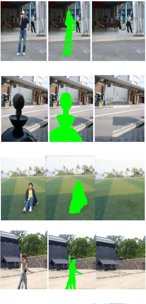
Fig. 3 shows the results obtained using the Proposed Method. Various images are considered as an Original Image, Mask image is also provided and the third column gives the resultant image. The proposed algorithm outperforms the others, giving more plausible results.
a) Original Image b) Mask Image
c) Criminisi’s Approach d) Bornemann’s Approach (PSNR=90,Time=114s) (PSNR=93,Time=110s)
e) Our Proposed Method (PSNR=95,Time=98s) Fig. 2 Results for object removal.
a) Original Image b) Mask Image c) Output
a) b)
c) d) Fig. 4 Influence of patch size on the Input Image (a)
TABLE I.
INFLUENCE OF PATCH SIZE ON INPUT IMAGE A
Input
Image Patch size PSNR Time
b) 2 17.40 169s
c) 4 17.27 119s
d) 5 17.28 109s
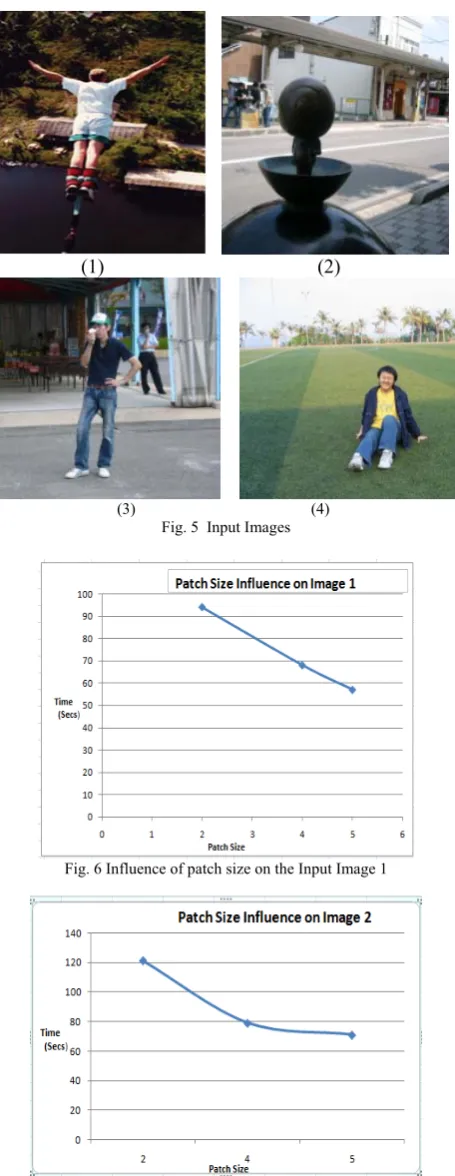
Fig 4 illustrates how the choice of patch size affects the quality of the inpainted image. Table 1 shows the influence of patch size on the input image. Smaller patch sizes allow more matching possibilities without capturing the image structure, and this does not always permit to obtain a good reconstruction. Up to a certain limit, a bigger patch size can capture the texture characteristics better, however with less matching possibilities. From the experiments we conclude that larger patch size permits to obtain satisfactory results in lesser time. Fig 5.shows set of input images. From these images we have made graphs according to varying patch size.Fig 6.shows the influence of patch size on image 1.As shown in fig, as the patch size increases the time taken to inpaint the image is reduced. Here, we have consider 3 patch sizes i.e.2,4,5 for result analysis.
Likewise Fig 7,8,9 shows the patch size influence on the input images 2,3 and 4.So if we select bigger patch size to inpaint the image we get good quality results and within lesser time.
(1) (2)
(3) (4) Fig. 5 Input Images
Fig. 6 Influence of patch size on the Input Image 1
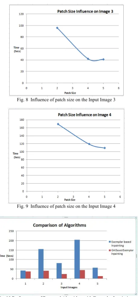
Fig. 8 Influence of patch size on the Input Image 3
Fig. 9 Influence of patch size on the Input Image 4
Fig. 10 Performance of Proposed Algorithm with Exemplar Inpainting .
Fig 10 shows the performance of our proposed method i.e GA based Exemplar Inpainting with the Exemplar Inpainting Method. As shown in fig, we can easily predict that using our proposed method we can inpaint the image in lesser time compared with the Exemplar based Inpainting algorithm.
VIII. CONCLUSION AND FUTURE SCOPE
This research is about how effectively GA is used for patch selection in exemplar based image in-painting method. In order to improve the computational complexity also the acceptable quality of the image GA is used. Multi-scale graph cut algorithm is used to efficiently solve the energy minimization problem .Our experiments show how well the proposed algorithm performs compared with other recent algorithms based on image in-painting.
For the Future scope we will relax the algorithm to do video in-painting. Real time object removal can be performed on the image. Objects can be easily removed from the videos.And Advance study includes growth of efficient algorithm to reduce computational cost and to decrease the time required for In-painting.
ACKNOWLEDGEMENTS
I express my gratitude to all anonymous researchers for providing us such helpful opinion, findings, conclusions and recommendations.
REFERENCES
[1] Z. Tauber, Z.-N. Li, and M. Drew, “Review and preview: Disocclusion by in-painting for image-based rendering,” IEEE Trans. Syst., Man, Cybern., C, Appl. Rev., vol. 37, no. 4, pp. 527– 540, Jul. 2007.
[2] M. Hay, G. Miklau, D. Jensen, P. Weis, and S. Srivastava, Anonymizing Social Networks,” Technical Report 07-19,Univ. of Massachusetts Amherst, 2007S. Zinger, L. Do, and P. H. N. de With, “Free-viewpoint depth image based rendering,” J. Vis. Commun. Image Rep., vol. 21, nos. 5–6, pp. 533–541, 2010.
[3] D. Liu, X. Sun, F. Wu, S. Li, and Y.-Q. Zhang, “Image compression with edge-based in-painting,” IEEE Trans. Circuits Syst. Video Technol., vol. 17, no. 10, pp. 1273–1287, Oct. 2007.
[4] Z. Xiong, X. Sun, and F. Wu, “Block-based image compression with parameter-assistant in-painting,” IEEE Trans. Image Process., vol. 19, no. 6, pp. 1651–1657, Jun. 2010.
[5] Y.-Q. Liu, J. Wang, and H.-H. Zhang, “Adaptive patch-based in-painting for image block recovery,” in Proc. Int. Conf. Comput. Vis. Theory Appl., 2010, pp. 52–59.
[6] S. Masnou, “Disocclusion: A variational approach using level lines,” IEEE Trans. Image Process., vol. 11, no. 2, pp. 68–76, Feb. 2002.
[7] M. Bertalmio, G. Sapiro, V. Caselles, and C. Ballester, “Image in-painting,” in Proc. ACM SIGGRAPH, 2000, pp. 1–8.
[8] F. Bornemann and T. Marz, “Fast image in-painting based on coherence transport,” J. Math. Imag. Vis., vol. 28, no. 3, pp. 259– 278, 2007.
[9] A. Efros and T. Leung, “Texture synthesis by non-parametric sampling,” in Proc. 7th Int. Comput. Vis. Conf., Sep. 1999, pp. 1033–1038.
[10] A. Criminisi, P. Pérez, and K. Toyama, “Region filling and object removal by exemplar-based image in-painting,” IEEE Trans. Image Process., vol. 13, no. 9, pp. 1200–1212, Sep. 2004.
[11] P. Perez, M. Gangnet, and A. Blake, “PatchWorks: Example-based region tiling for image editing,” Microsoft Research, Redmond, WA,Tech. Rep. MSR-TR-2004-04, 2004, pp. 1–8.
[12] M. Bertalmio, L. Vese, G. Sapiro, and S. Osher, “Simultaneous structure and texture image in-painting,” IEEE Trans. Image Process., vol. 12,no. 8, pp. 882–889, Aug. 2003
[13] . Z. Xu and J. Sun, “Image in-painting by patch propagation using patch sparsity,” IEEE Trans. Image Process., vol. 19, no. 5, pp. 1153–1165,May 2010.
[14] J. Sun, L. Yuan, J. Jia, and H. Shum, “Image completion with structure propagation,” in Proc. SIGGRAPH, 2005, pp. 861–868. [15] J. Jia and C. Tang, “Inference of segmented color and texture
description by tensor voting,” IEEE Trans. Pattern Anal. Mach. Intell., vol. 26, no. 6, pp. 771–786, Jun. 2004.
[16] N. Komodakis and G. Tziritas, “Image completion using efficient belief propagation via priority scheduling and dynamic pruning,” IEEE Trans.Image Process., vol. 16, no. 11, pp. 2649–2661, Nov. 2007.
[17] Y. Wexler, E. Shechtman, and M. Irani, “Space-time completion of video,” IEEE Trans. Pattern Anal. Mach. Intell., vol. 29, no. 3, pp. 463–476, Mar. 2007.
[18] Y. Yang, Y. Zhu, and Q. Peng, “Image completion using structural priority belief propagation,” in Proc. ACM Int. Conf. Multimedia, 2009, pp. 717–720.
[20] P. Arias, G. Facciolo, V. Caselles, and G. Sapiro, “A variational framework for exemplar-based image in-painting,” Int. J. Comput. Vis., vol. 93, no. 3, pp. 319–347, 2011.
[21] V. Kwatra, I. Essa, A. Bobick, and N. Kwatra, “Texture optimization for example-based synthesis,” in Proc. SIGGRAPH, 2005, pp. 795–802.
[22] L. Demanet, B. Song, and T. Chan, “Image in-painting by correspondence maps: A deterministic approach,” in Proc. VLSM, 2003, pp. 1–8.
[23] J. Aujol, S. Ladjal, and S. Masnou, “Exemplar-based in-painting from a variational point of view,” SIAM J. Math. Anal., vol. 42, no. 3, pp. 1246–1285, 2010
[24] C. Barnes, E. Shechtman, A. Finkelstein, and D. B. Goldman, “Patch-match: A randomized correspondence algorithm for structural image editing,” in Proc. SIGGRAPH, 2009, pp. 1–11. [25] G. Peyre, “Manifold models for signals and images,” Comput. Vis.
Image Understand., vol. 113, no. 2, pp. 249–260, 2009.
[26] A. Bugeau, M. Bertalmo, V. Caselles, and G. Sapiro, “A comprehensive framework for image in-painting,” IEEE Trans. Image Process., vol. 19, no. 10, pp. 2634–2645, Oct. 2010.
[27] V. Kolmogorov and R. Zabih, “What energy functions can be minimized via graph cuts?” IEEE Trans. Pattern Anal. Mach. Intell., vol. 26, no.2, pp. 147–159, Feb. 2004.
[28] Y. Pritch, E. Kav-Venaki, and S. Peleg, “Shift-map image editing,” in Proc. Int. Conf. Comput. Vis., Sep. 2009, pp. 151–158.
[29] L.I.Rudin, S. Osher, and E. Fatemi, “Nonlinear total variation based noise removal algorithms,” Phys. D, Nonlinear Phenom., vol. 60, nos.1–4, pp. 259–268, 1992.