Transient and Mode Shape Analysis of Gravity Roller Conveyor for
Weight Reduction
Mr. Rajratna A. Bhalerao1, Dr. R.J. Patil2
1
Department of Mechanical Engineering.
2
Department of Mechanical Engineering.
ABSTRACT
One of the major equipment in material handling is roller conveyor. As the roller conveyors are not generally subjected to complex state of stress they can be designed by providing higher factor of safety it leads to unnecessarily increase in material cost. This can be reduced effectively by separately designing conveyor part and testing whole assembly for transient and mode shape analysis for critical parts.
Keywords—About four key words or phrases in
alphabetical order, separated by commas.
I.
INTRODUCTION
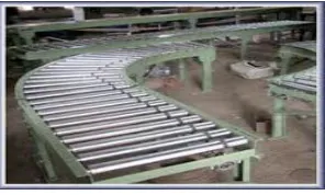
A conveyor system shown in Fig 1.1 is a common piece of mechanical handling equipment that moves materials from one location to another. Conveyors are especially useful in applications involving the transportation of heavy or bulky materials. Conveyor systems allow quick and efficient transportation for a wide variety of materials, which make them very popular in the material handling and packaging industries. Many kinds of conveying systems are available, and are used according to the various needs of different industries. There are chain conveyors (floor and overhead) as well. Chain conveyors consist of enclosed tracks, I-Beam, towline, power & free, and hand pushed trolleys.
Fig : 1.1- Roller Conveyor
Conveyor systems are used widespread across a range of industries due to the numerous benefits they provide.
• Conveyors are able to safely transport materials from one level to another, which when done by human labor would be strenuous and expensive. • They can be installed almost anywhere, and are
much safer than using a forklift or other machine to move materials.
• They can move loads of all shapes, sizes and weights. Also, many have advanced safety features that help prevent accidents.
• There are a variety of options available for running conveying systems, including the hydraulic, mechanical and fully automated systems, which are equipped to fit individual needs.
II. OBJECTIVEOF PRESENT STUDY
The following are the objectives of the study:
1. Study existing roller conveyor system and its design.
2. Geometric modeling of existing roller conveyor.
3. To carry out linear static, modal, transient and optimization analysis of existing roller conveyor.
4. Modification of critical conveyor parts for weight optimization.
5. To carry out analysis of modified design for same loading condition.
6. Recommendation of new solution for weight optimization.
III. SCOPEOF PRESENT STUDY
1. Check design of existing conveyor system. 2. Simulation method applied to optimizeparameters web thickness, flange thickness, web height, roller thickness and shaft diameter.
3. 150 simulations for linear static Analysis. 4. 150 simulations for modal Analysis.
5. Optimization of conveyor assembly for weight reduction.
6. Comparison between existing and optimized design.
IV. METHODOLOGY
TRANSIENT DYNAMIC ANALYSIS (By using Ansys 14.5)
forces in a structure as it respond to any combination of static transient and harmonic load. The time scale of the loading is such that the inertia or damping effect is considered to be important.
MODAL ANALYSIS (By using Ansys 14.5)
Modal analysis is used to determine the vibration characteristics (natural frequencies and mode shapes) of a structure or a machine component while it is being designed. It also serves as a starting point for another more detailed analysis, such as a transient dynamic analysis a harmonic response analysis or a spectrum analysis. Modal analysis also used to determine the natural frequencies and mode shapes of a structure. The natural frequencies and mode shapes are important parameter in the design of a structure for dynamic loading condition. Allowable Limit.
Excitation Frequency 50 Hz.
Maximum deflection 1.8 mm.
Maximum stress 70 MPa.
IV. EXSITING MODEL PARAMETERS
Fig : 4.1- Existing Model Details.
Table 4.1 Critical Parameters of Existing Assembly
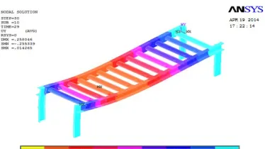
Natural Frequency 60.383 Hz.
Maximum deflection 0.3mm.
Maximum stress 32.76MPa.
Fig : 4.2 Critical Mode Shape
PROCEDURE TO PERFORMING FULL TRANSIENT DYNAMIC ANALYSIS
• Build the Model
• Establish Initial Conditions • Set Solution Controls
• Set additional Solution Options • Apply the Loads
• Save the Load configuration for the current load Step
• Repeat Steps 3-6 for Each Load Step • Save a Backup Copy of database • Start the transient solution • Exit the solution processer Deflection Plot :
Fig.: 4.3 – Maximum Deflection on Step 1 Transient Analysis.
Fig.: 4.5 – Maximum Deflection on Step 5 Transient Analysis.
Stress Plot :
Fig.: 4.6 – Maximum Stress on Step 1 Transient Analysis.
Fig.: 4.7 – Maximum Stress on Step 20 Transient Analysis.
As we can see from the results obtained that the factor of safety is higher and there is scope of optimization by reducing the factor of safety used in design, we can redesign the system which will give us comparatively less weight, further material and cost saving.
So optimization is to be done and suitable channels are to be selected from available channels. As we can have higher deflections and stresses than present values, we will redesign the system for those values which are safer as well as will reduce weight of the system.
Again the values should match the standard channel values so that the channels would be easily available in market, so redesigning the system for available channels.
Optional Channels available are:
ISMC 75 x 40 ISJC 75 x 22 ISMC 100 x 50 ISJC 100 x 45 ISMC 125 x 65 ISJC 125 x 50
V. DESIGN ANALYSIS AFTER WEIGHT
REDUCTION
After studying number of iteration for various Parts of roller conveyor a optimized design can be selected on the basis of following parameter.
Fig.: 5.1 Roller Thickness V/S Deflection
Fig.: 5.2 Roller Thickness V/S Stress
Fig.: 5.4 Web Height V/S Stress.
Similarly after finding suitable values of other component following parameters are selected for weight reduction Sr.
No. Name of Component Weight (kg)
1 C- Channel for Chassis 25.49
2 Rollers 74.54
3 Shafts 19.359
4 Bearing 2.7944
5 C- Channel for Supports 6.9516 Total Weight of the assembly 129.135 Table 5.1 Parameters of Optimized Design
Modal Analysis
Fig. 5.5 : Natural Frequency Of Optimized Design
Transient Analysis
Fig.5.6 Maximum Deflection On Step 1 Transient Analysis Of Optimized Design
Fig.: 5.7 Maximum Deflection On Step 1 Transient Analysis Of Optimized Design
Fig.5.8 maximum Stress on Step 1Transient Analysis of Optimized Design
Fig.5.9 Maximum Stress on Step 30 Transient Analysis of Optimized Design
VI. VALIDATION
.Validation:Validation or verification, in engineering is, `confirming that a product or service meets the needs of its users.’
Software results should be compared with appropriate theoretical results whenever possible. In most cases, one would use theory to obtain order-of-magnitude estimates rather than to make a head-to-head comparison since presumably FEA is being used because a theoretical solution is not available.
An important step in the analysis is to make sure that the mesh resolution is adequate for the desired level of accuracy. This is done by refining the mesh and comparing results obtained with different levels of mesh resolution. So the numerical result has to be compared with either analytical results or with experimental results, to ensure as per requirement working and the safety of the component.
11.2Validation for Conveyor Assembly:
Numerical solution is done for optimized model and the results are compared with the experimental results.
Actual physical model is done for validation using optimized design parameters and it is found that the design is working safely.
Compare to existing design the changes are made in three parts viz. C-channel for chassis, C-channel for support and roller.
As the parts in which changes are made in existing design are standard so made easily available in market and are assembled for testing on which 350 kg load is applied and safety is checked.
The weight of the physical model is slightlyless than the optimized model values, shown in below table.
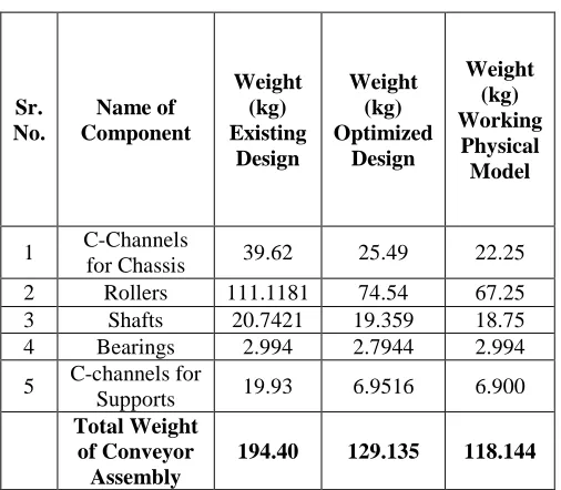
Table 6.1 Weight of Assembly
Sr. No. Name of Component Weight (kg) Existing Design Weight (kg) Optimized Design Weight (kg) Working Physical Model
1 C-Channels
for Chassis 39.62 25.49 22.25 2 Rollers 111.1181 74.54 67.25 3 Shafts 20.7421 19.359 18.75 4 Bearings 2.994 2.7944 2.994
5 C-channels for
Supports 19.93 6.9516 6.900 Total Weight
of Conveyor Assembly
194.40 129.135 118.144
- Optimized design values are used in actual physical model build up.
Detail comparison of Optimized design Analytical and Working physical model:-
1) The C- Channel for chassis used is ISJC 100 whose weight by analytically is 25.49 kg and compare to that with physical is 22.25 kg. 2) The C- Channel for support used is ISJC 75
whose weight by analytically is 6.95164 kg
and compare to that with physical is 6.900 kg.
3) The roller whose dimensions are D = 65 mm previously it was 70mm has74.54 kg weight by analytical calculations while it has 67.25 kg weight in actual.
4) The shafts analytically having weight 19.359 kg which in actual is 18.75kg.
• The overall change in analytical values and physical values are 8.5 %.
• The difference in the weight is due to the case of manufacturing the components at lower limit values compare to the software where real values are used.
VII. CONCLUSION
1) Result of linear static analysis shows the difference between maximum deflection and stress in existing and optimized design is negligible.
2) Result of transient analysis shows there is negligible difference between maximum deflection and stress in existing and optimized design.
3) Even there is some difference in deflection and stresses of existing and optimized design, but it is in permissible limit.
4) As deflection and stresses are in permissible limit for optimized design, it is safe for given application and gives reduction of 65.27 kg. Table 12.1 shows weight reduction due to optimized design.
5) Critical parameter which reduces the weight are C-channels, roller outer diameter and roller thickness.
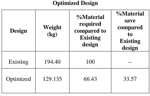
6) Optimized design has 66.43% weight that of existing design as shown in table 12.2.
7) 33.57% weights reduced due to optimization i.e. 33.57% material is saved.
Table 7.1 Effect of Optimized design on maximum deflection, stresses and natural frequency
Design Max. Def (mm)
Natural Freq. (Hz)
Max. Stress (N/mm2)
Existing 0.327 60.383 32.762
Table 7.2 Weight reduction and material saving due to
Optimized Design
Design Weight
(kg)
%Material required compared to
Existing design
%Material save compared
to Existing
design
Existing 194.40 100 --
Optimized 129.135 66.43 33.57
REFERENCES
[1]. M. A. Alspaugh, “Latest Developments in Belt Conveyor Technology”MINExpo 2004, Las Vegas, NV, USA. September 27, 2004.
[2].S.H. Masood · B. Abbas · E. Shayan · A. Kara “An investigation into design and manufacturing of mechanical conveyors Systems for food processing”,
Springer-Verlag London Limited 2004.
[3]. DimaNazzal , Ahmed El-Nashar“Survey Of Research In Modeling Conveyor-Based Automated Material Handling Systems In wafer fabs” Proceedings of the 2007 Winter Simulation Conference.
[4]. Chun-HsiungLan, “The design of a multi-conveyor system for profit maximization” International Journal AdvManufTechnol (2003) 22: 510–521.
[5]. John Usher, John R , G. Don Taylor “Availability modeling of powered roller conveyors”.
[6].Espelage W, WankeE.“Movement minimization for unit distances in conveyor flow shop processing”. [7].C.Sekimoto “Development of Concept Design CAD
System”, Energy and Mechanical Research Laboratories, Research and Development Center, Toshiba Corporation.
[8]. Ying WANG, Chen ZHOU “A Model and an analytical method for conveyor system in distribution centers”, J SystSciSystEng (Dec 2010) 19(4): 408-429.
[9]. R. Long, T. Rom, W. H¨ansel, T.W. H¨ansch, J. Reichel “Long distance magnetic conveyor for precise positioning of ultra cold atoms” Eur. Phys. J. D 35, 125–133 (2005).
[10] R. Pascual, V. Meruane, “Analysis of transient loads on cable-reinforced conveyor belts with damping consideration”, Proceedings of the XXVI Iberian Latin-American congress on computational methods in engineering CILAMCE 2005 Brazilian Assoc. for comp mechanics & Latin American assoc of comp
methods in engineering, Guarapari, Espirito Santo, Brazil, 19th -21st October 2005. Paper CIL0620. [11] A. Harrison, “non-linear belt transient analysis by
numerical simulation”, Bulk Solids Handling International journal, Nr. 3, 2008, Page no 1-7.
[12] ChetanKothalkar, T. Wankar, R.S. Wankar, “Analysis of the short distance gravity actuated oscillatory trolley conveyor”, 14th National Conference on machines and mechanisms (NaCoMM09), NIT, Durgapur, India, December 17-18, 2009, NacoMM2009-ASMCK24. Page no 84-90.