Microcontroller Based Keypad Operated Door System with Alarm,
A Technical Approach to Improve Commercial Bank Vault Security
Oyebola B. O.
Department of Electrical/Electronics Engineering, Gateway (ICT) Polytechnic Saapade, Nigeria [email protected]
Abstract –
Opening a lock with the use of a PIN adds more flexibility to security system. This thesis describes the design and implementation of a Microcontroller based security system for home and office devices. It provides users with an efficient and reliable security system that supports the use of an Electronic Keypad arranged to send signals to the control unit. This Control Unit either activates the Port to which the LED (the door Latch) is connected when the correct Pin is entered or activates the Port to which the Buzzer Alarm is connected when the wrong Pin is entered. The prototype of the system is successfully implemented according to the proposal giving authorized user the privilege to change the Pin at will. Overall, the design and implementation of the prototype is fully functional and user friendly.
Keywords: Bank; Keypad; Microcontroller; Bank; Vault
1.0 OVERVIEW
Due to the need to increase the security of life and properties in our environment, security systems are used as selective systems to decide who has access to a given location based on a personal distinctive trait of the user. It also serves the function of sensing or detecting false intrusion (using input sensory devices and gives early warning using audio warning devices alarm – light indicators and remotely controlled computer systems). The term false intrusion here is used to mean any form of attempt to gain entry without following the proper pre-designed protocol(s)[1].
From time past until present, security locks usually includes mechanical devices made of forged metal i.e. simple lock and bolt, the door chain, pin tumbler lock, the jam lock and padlock etc. Other recently developed security devices are gadgets like laser beam detectors, motion detectors and magnetic card readers. Most recent of these devices are offshoots of biometric engineering. They include voice recognition systems, finger print readers, retina eye scanners etc. The major characteristic of security devices is to prevent an intruder from gaining access to a location. Most of these devices however have lapses which give an unauthorized person access
device, by conditioning the access based on the configuration of the security device thereby granting access to the user with correct pin number[2]. The microcontroller based electronic lock finds application in homes, banks in the field of military applications i.e. ammunition ware house, industries, ministries and government set-up.
This proposed system aimed to provide a security lock that is efficient and reliable, at cheaper price in comparison with traditional devices, implement a security system which gives authorized users the privilege to change their personal identification numbers any time, provide opportunity of textual displays as compared to conventional ones which only show digits. and reduce the bulkiness characterized with other security locks of its type by the use of a microcontroller, the PIC16F877A.
The existing type of this project has less functions and security compared to this project. From time past until present, security locks usually includes mechanical devices made of forged metal i.e. simple lock and bolt, the door chain, pin tumbler lock, the jam lock and padlock which can easily be broken when heated with harden material. Other recently developed security devices are gadgets like laser beam detectors, motion detectors and magnetic card readers which can easily be by passed. Therefore, with this project rigid security can be enhanced to provide security for life and properties.
The main purpose of this project is to construct a circuit that will be controlled by PIC to secure access-controlled zones by restricting access to zones to only those persons (or assets) who are allowed to access a building by securing the building with a password.
2.0BACKGROUND OF THE STUDY
When we think of locks, we think of a bolt containing a notch known as a talon, which is operated by moving the bolt backwards or forward by engaging a key in the talon. But there
a mechanical device that can be used for securing doors, cabinets, lid of brief cases or other luggage. It consists essentially of a bolt guarded by a mechanism which can be released by a mechanical, hydraulic or electrical/electronic actuator.
The oldest known mechanical functioning lock was an Egyptian door lock used about 2000BC, made of wood and fastened vertically on the door post, the wooden block contained movable pins or “pin tumblers” that dropped by gravity into openings in the cross piece of “bolts” and locked the door. It was operated by a wooden key with pegs that raised the number of tumblers sufficiently to clear the bolt so that it could be pulled back. The major disadvantage with it is that it was wholly made of wood [2].
The Romans made an improvement on this by fabricating the first metal locks which was later improved by Robert Barson, an English man in 1778 and Linus Yale Jnr an American in 1861. The Yale lock consists of essentially a cylindrical plug placed in an outer barrel. The plug is rotated and in turn moves the bolt of the lock by means of a cam. The inserted key raises five pins of different sizes into corresponding holes in the plug. The most common form of cylindrical lock used in homes is the so-called night latch, operated from a key from outside and a knob from inside. In the 20th century, as machine tools and
manufacturing methods became more
sophisticated, locks were produced, which are either key operated (opened) or keyless. In the late 20th century, electromechanical locks were developed to trip electrical circuit as seen in automobile ignitions. Other keyless locks include remote controlled lock, “security card” operated and electronic code lock.
Microcontrollers are designed for embedded applications, in contrast to the microprocessors used in personal computers or other general purpose applications[3]. Microcontrollers are used in automatically controlled products and devices, such as automobile engine control systems, implantable medical devices, remote controls, office machines, appliances, power tools, toys and other embedded systems.
The first microprocessor was the 4-bit Intel 4004 released in 1971, with the Intel 8008 and other more capable microprocessors becoming available over the next several years. However, both processors required external chips to implement a working system, raising total system cost, and making it impossible to economically computerize appliances.[4]
Partly in response to the existence of the single-chip TMS 1000, Intel developed a computer system on a chip optimized for control applications, the Intel 8048, with commercial parts first shipping in 1977. It combined RAM and ROM on the same chip[5].
Microcontrollers were originally programmed only in assembly language, but various high-level programming languages are
now also in common use to target
microcontrollers. These languages are either designed specially for the purpose, or versions of general purpose languages such as the C programming language. Compilers for general
purpose languages will typically have some restrictions as well as enhancements to better support the unique characteristics of microcontrollers. Some microcontrollers have environments to aid developing certain types of applications. Microcontroller vendors often make tools freely available to make it easier to adopt their hardware[6]. A microprocessor differs from a microcontroller in many ways. The main difference is that a microprocessor requires several other components for its operation, such as program memory and data memory, I/O devices, and external clock circuit. A microcontroller on the other hand has all the support chips incorporated inside the same chip. All microcontrollers operate on a set of instructions (or the user program) stored in their memory. A microcontroller fetches the instructions from its program memory one by one, decodes these instructions, and then carries out the required operations.
3.0 THE SYSTEM DESIGN
3.1 Hardware Design Considerations
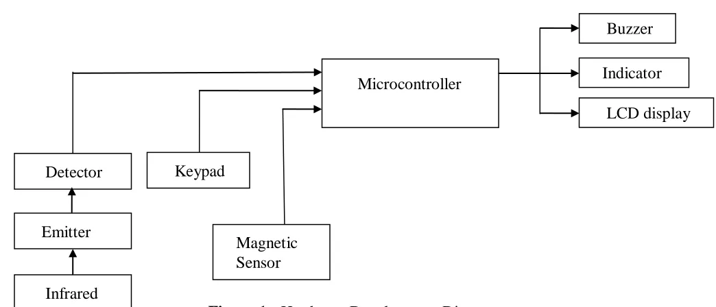
Figure 1: Hardware Development Diagram
DETECTOR: It is a device or instrument designed to detect the presence of a particular object or
substance
EMITTER: It is a device that discharges a signal or other substance. In terms of electronics
INFRARED: Infrared is a form of light... light that we can not see with our eyes, but that we can sometimes feel on our skin as heat. When we think of light, we may imagine the glare of the Sun on a summer day, or the soft glow of a light bulb at night.
KEYPAD: A keypad is a set of buttons arranged in a block or "pad" which usually bear digits, symbols and usually a complete set of alphabetical letters. If it mostly contains numbers then it can also be called a numeric
keypad.
MAGNETIC SENSOR: Magnetic Sensors were used for speed, rotational speed, linear position, linear angle and position measurement in
automotive, industrial and consumer
applications.
MICROCONTROLLER was the system
processor.
BUZZER: was used for electrical alarm
INDICATOR: it indicate the tension on the main spring on any particular moment
LCD display: it converts 1s and 0s into image, it has the function of powering it ON and OFF, it control the brightness contrast and position.
The hardware development is divided into three stages as shown in block diagram above. The input stage of the security system is the motion detector circuit, keypad, and magnetic sensor. The second stage is the controller unit which is the microcontroller PIC16F1508 The purpose of using microcontroller is to control the whole system operation by sending data to the output stage which is the LCD display, indicator and buzzers.
Detector
Magnetic Sensor
Infrared
Keypad
Buzzer
Emitter
Microcontroller Indicator
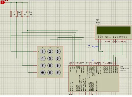
Figure 2: The System Circuit Diagram
The diagram of the circuit used in the project is shown in Figure 2.
1. Voltage regulator (LM7805): A LM7805 Voltage Regulator is a voltage regulator that outputs +5 volts.
2. Capacitors: A capacitor (originally known as a condenser) is a passivetwo-terminalelectrical component used to store energyelectrostatically in an electric field.
3. Resistors: A resistor is a passivetwo-terminalelectrical component that implements electrical resistance as a circuit element. The current through a resistor is in direct proportion to the voltage across the resistor's terminals.
4. A light-emitting diode (LED) is a semiconductor light source.[7] LEDs are used as indicator lamps in many devices and are increasingly used for general lighting. Appearing as practical electronic components in 1962,[8] early LEDs emitted low-intensity red light, but modern versions are available across the visible, ultraviolet, and infrared wavelengths, with very high brightness.
5. Keypad: This is used to input the password into the project.
The Figure 3 shows the internal structure of the 4x4 keypad used in this project. Different brand or manufacturer of keypad has different architecture and number of pin. For this kind of keypad, it consists of 8 pins and the internal connection is
illustrated in Figure 3. When button 3 is pressed, the column 3 and row 1 will short while the others are open
Figure 3: 4X4 Keypad
3.2 The Software Design
Microcontroller Algorithm 1. Start
2. Microcontroller a. PORTC to keypad b. PORTA.0 to PIR(sensor) c. PORTA.1 to red led d. PORTA.2 to green led e. PORTA.4 to buzzer 3. Initial configuration a. Flash red led, green led b. Buzz for some seconds
c. Go to disable state and on the green led 4. Endless loop
5. If motion is detected and in active state a. Red led is on
b. Buzz
6. If motion is not detected and in active state a. Red led on
b. Buzzer off
7. If motion is detected or not detected and in disable state
a. Green light on b. Buzzer off 8. Keypad function 9. End endless loop 10.End
Keypad Algorithm 1. If keypad pressed Blink red led
2. If keypad pressed three time
b. Else blink red three times
3. If keypad pressed is less keys and after 5 seconds
Blink red led three time
3.3 System Operation
The sequence of the system operation is as shown in Figure 4. To deactivate the system where
opening door without alarm, user must enter the deactivation code. The chance to deactivate the system is once before keypad locked, where user can not enter the code anymore. If deactivation code was correct, green LED will „ON‟ while „OFF‟ condition. System at this time is successfully deactivated and user can
open the door without alarm.
Figure 4: Operation Flow chart of the System Start
Door close
Password
Door open
Password Password
Pass word System „off‟ (magnetic switch, infrared, buzzer „off‟)
Buzzer „on‟ System „on‟
(magnetic switch infrared „on‟)
4.0 CONSTRUCTION
This section discuss about design validation, breadboard implementation, testing and result.
4.1 Design validation
The best workable circuit was devised taking into consideration some parameters such as polarity, amount of current entering into components, compatibility of components. A very important advantage to design validation is the use of a software package such as ORCAD PSPICE to simulate the design circuit before implementation.
4.2 Bread Board Implementation
The circuit design was implemented on the bread board after validating it on circuit simulator. During this stage, various parameters like voltage drops, input current were measured in order to ensure good result. The circuit design was tested on the board and found to be working properly before soldering on the panel board.
4.3 Vero board implementation
After proper verification on the breadboard, the design was transferred to a veroboard for permanent construction. The various module of the design were soldered and arranged on the Vero board such that each module can be easily identified. Before proper soldering, component layout plan was drawn paying particular attention to minimize the distances involve between point to be connected and the prevention of the overcrowding.
4.4 Testing and result:
In testing the following stages are carried out; 1. Each of the components was first tested using multimeter in order to check for their state of performance and accurate values.
2. The polarities was also tested
3. An the connection of each component on the board was then tested, this was done in other to carry out the continuity, which is meant for proper connection of the circuit and to detect any wrong connection.
4. The PIC and the IC pins are then checked to know exact pin to their numbers
5. After the proper testing of the peripherals and found to be working perfectly, the entire circuit was tested. Series of programs (soft wares) were written and tested before the working programs was fully achieved. The circuit worked perfectly as designed. The display unit was also observed during the testing.
5.0 CONCLUSION
In conclusion, keypad operated door is constructed to guarantee ease and security in the entry and exit of a bank vault door. The keypad operated door reduces the force, stress, and applied when aiming to open a door with a metal handle or all other types of door which are of lower technology. The device allows the user to open the door with a given password. The device gives the user the freedom to enter and exit without stress, or offering more energy to manipulate handles or all sort of door openers of low technology. This system guarantees bank vault door security from unauthorized used, in the sense that “no correct password no entry”.
REFERENCES
[1] SaurabhVinayak Lawate1 and M. S. Ali (2014). Electronic Eye for Security System. International Journal of Electronic and Electrical Engineering.
[2] ISSN 0974-2174 Volume 7, pp. 961-970 Retrieved on 12th August 2015, from
http://www.ripublication.com/irph/ijeee_ spl/ijeeev7n9_10.pdf
[3] Martin Bates(2000) “introduction to
Microelectronic system”, The
PIC16F877AMicrocontroller system security Eng.J., Vol.3 No1.pp4-8.http://en.wikipedia.org/wiki/Integrated _circuit
[5] Augarten, Stan (1983). "The Most Widely Used Computer on a Chip: The TMS 1000".
[6] State of the Art: A Photographic History of the Integrated Circuit (New Haven and New York: Ticknor & Fields). ISBN 0-89919-195-9. Retrieved 2009-12-23.
[7] Programming Language.
http://en.wikipedia.org/wiki/C_(program ming_language)
[8] Nick Holonyak, Jr. (2004). Lemelson-MIT Prize Winner". Lemenson-Lemelson-MIT Program.
[9] LED. The American heritage science dictionary. Houghton Mifflin Company. 2005. led and LED. Retrieved on 12th
August 2015, from
http://archive.computerhistory.org/resour ces/