An Effective Turn around Converter Plan through Parallel Prefix
Adder
HUMA AFREEN1, KASARLA MOUNIKA2,
1,2
Assistant professor © Dept of ECE
University College of Engineering and Technology, Mahatma Gandhi University, Nalgonda, Telangana, India.
ABSTRACT: - In this paper, the usage of deposit number framework turn around converters in view of half breed parallel prefix adders is broke down. The parallel prefix viper gives rapid and lessened defer number juggling operations yet it isn't broadly utilized since it experiences high power utilization. Consequently, a cross breed parallel prefix snake segment is exhibited to perform quickly modulo expansion in Deposit Number Framework turn around change. The proposed parts are not just outcomes in quick number juggling operation and it likewise exceptionally diminished the equipment many-sided quality since it requires less measure of rationale components. In this work, the proposed parts are actualized in various moduli sets turn around converter outlines and the exhibitions are looked at for changed estimations of n.
KEYWORDS: -Digital arithmetic, parallel-prefix adder, residue number system (RNS), reverse converter.
I.
INTRODUCTION
The Deposit Number Framework assumes a noteworthy part in the battery based and compact gadgets due to its low power highlights and its focused deferral. The Buildup number framework turn around converter is outlined with parallel prefix expansion by utilizing new segments technique for higher speed operation. The RNS comprises of two principle segments forward and the turnaround converter that are coordinated with the current advanced framework. The forward converter plays out the operation of changing over the double number to the modulo number while the turnaround converter plays out the operation of invert changing over the modulo number to the parallel number which is the hard and tedious process contrasted and the forward converter. The principal RNS ideas, for example, 1)RNS definition with properties and their applications,2)consideration of modulo set selection,3)design of forward converter,4)modulo arithmetic units,5)design of turnaround converter are talked about.
The voltage over scaling (VOS) procedure is connected to the deposit number framework to accomplish high vitality productivity. The VOS strategy presents delicate mistakes which corrupts the execution of the framework. To beat these delicate mistakes another method is actualized called joint RNS-RPR (JRR) which is the mix of RNS and the decreased accuracy excess. This strategy gives the benefit of fulfilling the essential properties of RNS incorporates shorter basic way, lessened intricacy and low power. New structures are exhibited for the
moduli set (2n-1,2n, 2n+1) for the change from the buildup to the paired reciprocals. Here the speed and the cost are significant concern.
Appropriated number-crunching standards are utilized to play out the internal item calculation. The info information which are in the deposit area which are encoded utilizing the Thermometer code arrange and the yields are encoded utilizing the one hot code design. Contrasted with the ordinary technique which utilized twofold code organize, the proposed framework which accomplishes higher working pace. The deposit number framework which gives convey free expansion and completely number-crunching operation, for a few applications, for example, computerized flag preparing and cryptography.
In this concise, we introduce a thorough technique which utilizes the parallel prefix viper in chose position, along these lines utilizing the move operation on one piece left to plan a multiplier on a similar outline module to accomplish a quick turnaround converter plan. The use on parallel prefix structure in the plan prompts higher speed in operation then it expands the zone and power consumption.Inorder to repay the tradeoff between the speed, territory and power utilization, a novel particular crossover parallel prefix based viper segments are utilized to outline the turnaround converter.
II.
PARALLEL PREFIX
STRUCTURE
The Buildup number framework for the most part made out of three fundamental parts, for example, forward converter, modulo math units and turn around converter. On contrasting and alternate parts the switch converter configuration is a complex and no particular structure. So more consideration is required in planning the turnaround converter in this manner keeping the moderate operation and bargains the advantages of the RNS. The parallel prefix structure accomplishes the speedier operation in the switch converter configuration yet causes expanded power utilization. In the current framework the novel particular mixture parallel prefix viper based segments are utilized to supplant the current segments there by lessening the power utilization and getting quicker operation.
Parallel Prefix Block.
Fig.1 Basic Parallel prefix structure
The Parallel prefix structure consists of three main blocks, they are preprocessing block, prefix carry tree and post processing block. The parallel prefix adder operation begins with preprocessing stage by generating the Generate (Gi) and Propagate (Pi)
equation[1]&[3].The prefix carry tree get proceeded with the previous block signal to yield all carry bit signal and these stage contains three logic complex cells such as Black cell, Gray cell and Buffer cell. Black cell compute both the propagate (P(i,j)) and generate (G(i,j)) by using the equation[3]&[4].The Gray cell executes only the generate(G(i,j)).The carry bits generated in the second stage get passed to the post processing block thereby generating the sum using the equation[5].The block diagram is shown in the Fig1.
Gm:n=An AND Bn (1) G0 =Cin (2)
Pm:n=An XOR Bn (3) P0=0 (4)
Gm:n=Gn:k OR Pn:k AND Gk-1:n (5) Pm:n=Pn:k AND Pk-1:j (6)
Sn =Pn XOR Cin (7)
The Brent Kung adder prefix structure is employed to achieve the higher speed with reduced power consumption. On comparing with the other parallel prefix adder structure the BK adder is chosen mainly for minimum fan-out and should be higher speed in operation than others.Fig.2shows the example BK adder prefix structure which uses the three basic cells in the prefix structure. These structure is elaborated for the proposed design having the modulo addition of (4n+1) for n=5.
Fig.2:4-bit BK adder prefix structure
Fig.3 HRPX Structure using BK prefix network
Fig.3 shows HRPX Structure. The regular parallel prefix adder is used to do the first part of addition and the simplified RCA logic is used to do the second part where the corresponding bits of the operand are fully variable. Full adder can be designed with XOR/OR gates because of the constant operand. In these reverse converters design the carry chain is not needed and can be ignored. For most modulo sets (2ⁿ-1) addition is a necessary operation. The End around Carry (EAC) for (2ⁿ-1) addition is represented with two zero, but for the reverse converter design one zero representation is required. To correct these zero representation problem, a detector circuit was
employed in the design but it incorporates additional delay. So, the Binary to excess one converter (BEC) is used to solve the double zero representation issue.
III.
NEW
PARALLEL-PREFIX-BASED COMPONENTS
The HMPE Structure consists of two parts: Regular prefix adder and the Modified Excess One unit. The first two operands are added using the parallel prefix adder and the result is conditionally incremented based on the control signal generated by the prefix structure to assure the single zero representation. The below figure shows HMPE Structure.Fig.4: HMPE Structure
Modified Excess One unit Description
Fig.5: Modified Excess one unit
Fig.5 shows the Modified Excess One unit circuit diagram. The result generated by the prefix structure is conditionally incremented by this unit based on the control signal generated by the parallel prefix adder. The reverse converter design is implemented for (4n+1) modulo addition (n=5) designing the adder and also the multiplier by using the same adder
carry tree, this stage again computes the generate and propagate equation by using the previous output and all the logic cells employed in the Kogge Stone adder network. These processed signals are passed to the post processing block.
IV.
REVERSE CONVERTER
DESIGN METHODOLOGY
In this area, the system of turnaround converter configuration is depicted. In the accompanying, a strategy utilizing particular segments in the engineering of the turnaround converter will be displayed. A few invert converters for various moduli sets have been presented, which can be arranged intothree classes. The top of the line comprises of converters with a tree of CSAs with EAC took after by a two-operand modulo 2k − 1 CPA. A below average incorporates more mind boggling reverse converters, which have a few CSAs and CPAs with EACs took after by a last standard subtractor with two operands of various size. The execution of this subtractor utilizing general twofold snake brings about one operand with some steady bits. The second rate class covers the invert converters that have been intended for moduli sets with moduli other than the prevalent 2n and 2n ± 1. In the accompanying, we portray an approach for planning reverse converters in the first and second classes. The recommended strategy for applying the HMPE and HRPX in the invert converter is appeared in Fig.6.
Fig.6: Reverse converter design methodology
In the event that it is quite recently critical to accomplish the minimum power utilization and equipment cost without considering speed, no prefix viper is required. Then again, if fast is the originator objective, the CPAs with EAC and the standard CPAs ought to be supplanted by conventional parallel prefix modulo 2n – 1 adders and customary parallel-prefix adders, separately. Be that as it may, for the VLSI creators, a reasonable tradeoff between speed, power, and range is frequently more critical. For this situation, to start with, CPAs with the EAC can be supplanted by the HMPEs. At that point, if the converter contains a standard CPA where one of its operands has a string of steady bits with the estimation of one, it can be supplanted with the HRPX.
V.
EXPERIMENTAL RESULTS
Simulation Results:
The reproduction procedure has been done for various levels of deliberation. The code has been composed in Verilog equipment portrayal dialect. The best module has been orchestrated and reproduced in Xilinx ISE Plan Suite 12.3 and the relating defer counts have been noted. By utilizing Kogge Stone Snake the deferral and range was decreased.
Reproduction comes about are appeared in fig 7 and 8. RTL Schematic graphs are appeared in fig 9 and 10.The outline was executed in Austere 3E unit.
Fig.7: Simulation result of HMPE-BK Adder Parallel Prefix Structure
Fig.8: Simulation Result of HMPE-KS Adder Parallel Prefix Structure
RTL (Register Transfer Level) schematic diagrams:
Fig.10: RTL Schematic of HMPE- KS Adder Parallel Prefix Structure
Synthesize Result:
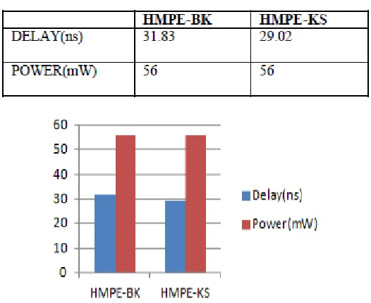
Table shows the synthesize result for using Xilinx project navigator for device xc3s400-4pq208
Table Synthesize result
Fig.11: performance and power trade-off of different system ADVANTAGES
Low power consumption. Delay and Area Low.
APPLICATIONS
VI.
CONCLUSION
This proposed work presents crossover parallel-prefix-based snake parts that give better tradeoff in zone and deferral are subsequently displayed to configuration turn around converters. An approach is portrayed to configuration invert converters relying upon different sorts of prefix adders. These segments are especially intended for switch converters. Usage comes about gives that the turnaround converters relying upon the recommended work essentially diminishes the region and postpone when differentiated and the first converters, which don't use any parallel-prefix adders. Future work incorporates the augmentation of the bit estimate and to develop a proficient switch converter.
REFERENCES
[1] Omondi and B. Premkumar, Residue Number Systems: Theory and Implementations. London, U.K.: Imperial College Press, 2007.
[2] B. Parhami, Computer Arithmetic: Algorithms and Hardware Designs, 2nd ed., New York, NY, USA: Oxford Univ. Press, 2010.
[3] J. Chen and J. Hu, “Energy-efficient digital signal processing via voltageover scaling-based residue number system,” IEEE Trans. Very Large Scale Integr. (VLSI) Syst., vol. 21, no. 7, pp. 1322–1332, Jul. 2013.
[4] C. H. Vun, A. B. Premkumar, and W. Zhang, “A new RNS based DA approach for inner product computation,” IEEE Trans. Circuits Syst. I, Reg. Papers, vol. 60, no. 8, pp. 2139–2152, Aug. 2013. [5] S. Antão and L. Sousa, “The CRNS framework and its application to programmable and reconfigurable cryptography,” ACM Trans. Archit. Code Optim., vol. 9, no. 4, p. 33, Jan. 2013.
[6] A. S. Molahosseini, S. Sorouri, and A. A. E. Zarandi, “Research challenges in next-generation residue number system architectures,” in Proc. IEEE Int. Conf. Comput. Sci. Educ., Jul. 2012, pp. 1658– 1661.
HUMA AFREEN received her B.Tech in ECE in
Nagarjuna college of
technology and science in the year 2012 and P.G. Received in ECE in Shadan
women’s college of
engineering and technology
in the year 2014. She is currently working as an assistant professor in ECE dept at University college
of Engineering and
Technology, Mahatma
Gandhi University,
Nalgonda, Telangana,
India. She has 3 years experience in teaching.
KASARLA MOUNIKA
received her B.Tech in ECE in SRTST, Nalgonda in the
year 2008 and P.G.
Received in ECE in SRTST, Nalgonda in the year 2011. She is currently working as an assistant professor in ECE dept at University college of Engineering and
Technology, Mahatma
Gandhi University,
Nalgonda, Telangana,