16
Multi-View Skeleton Pose Sequence
Selection for Human Activity Analysis
Petar NikolovP
1
P
, Ognian BoumbarovP
2
Technical University of Sofia
U
Abstract
Vision-based pose estimation and tracking of a human body is a problem of estimating kinematic parameters of the body model, such as joints position and joints angle, from a static image or a video sequence. In this paper, an estimation of a human pose using a multi-view camera system is performed. The constructed system is using a few stationary calibrated Microsoft Kinect devices, giving the pose sequence estimation for each of the views.
Keywords: human activity recognition; skeleton data clustering; calibrated Kinect devices; multi-view system using Kinects, pose estimation, multi-view skeleton pose sequence selection.
U
Introduction
Human pose recognition has been an active area of research for the past several decades due to its applications in activity recognition for surveillance, video games, robotics, etc. In the past few decades, several approaches have been proposed for recognizing human pose from monocular RGB video sequences [1]. Unfortunately, the monocular RGB data is highly sensitive to various factors like variability of human visual appearance in images, variability in lighting conditions, variability in human physique, partial occlusions due to self-articulation and layering of objects in the scene, complexity of human skeletal structure, high dimensionality of the pose, and the loss of 3d information that results from observing the pose from 2d planar image
projections. To date, there is no approach that can produce satisfactory results in general, unconstrained settings while dealing with all of the aforementioned challenges. Hence, despite significant research efforts over the past few decades, pose estimation still remains a challenging problem. A human body can be represented as an articulated system of rigid segments connected by joints, hence, if we can reliably extract and track the human skeleton, we can estimate the human pose. But extracting the human skeleton reliably from monocular RGB videos is a very difficult task [9]. By using RGB-D devices such as Microsoft's Kinect sensor Kinect, we can acquire the human's skeleton directly for each frame.
part-17
based approaches consider the human skeleton as a connected set of rigid segments (body
parts).
In this paper we are constructing a multi-view system with the idea to combine the pose estimation from each view, which is requiring a calibrated system. This system would be capable of selecting the most appropriate view for skeleton model for each frame - for improved state of the art pose estimation. In order to calibrate multiple Kinect devices, we have to overcome some limitations. The first one is to connect the sensors in a common system. Typically most computers cannot afford connecting more than one sensor due to the high USB bandwidth requirements from the second version of the Microsoft’s device. The second problem arises when using two devices having the same or partially covered FOV. The IR of each sensor interfere into the depth calculation of the other. Since the second problem is deeply analyzed in other articles [19], which are proposing installing a filters in front of the IR beams of each Kinect, changing the IR modulation or just changing the orientation of the sensors, so that there are no overlapping areas – In this article we are focusing on creating a system allowing to connect multiple devices and calibrate their color/depth images.
U
System architecture and Calibration
The illustration of the developed system is shown on Fig. 1. A server is connected to a N number of computers, each having one Kinect device connected. A TCP based protocol is written for the needs of this article used for data transfer, and a UDP based protocol – for discovery and new devices authentication. Those devices could be a regular PC, which would increase the cost of building such system or a low-cost single-board computer like Raspberry Pi.
Fig.1. System architecture
18
Fig. 2. “Discovery” connection diagram Fig.3. Calibration procedure diagram
There are multiple procedures developed for camera calibration over the years, the most famous one is by using a chart calibration boards placed in front of camera. For the purpose of this paper, we are using a rectangular object in the scene, visible to all cameras, which dimensions are known.
Our goal is to calculate the pose matrix P for each camera:
PP(1)
which is the product of the camera’s intrinsic and extrinsic matrixes. The intrinsic camera matrix K is: .
0 0
0 0
0
0 0 1
0 0 1 0 1 / 0
0 0 0 1 0 1 0
0 0 1 0 0 1 0 0 1
x
y
x x
y
f s x
K f y
f x s f
f y
T Sh
S
= =
× ×
(2)
The extrinsic camera matrix is calculated using:
3
3
0
0 1 D Translation
D Rotation
Т Т R
R I
= ×
(3)
where R is a 2D rotation matrix, and T is a translation matrix. Once the camera pose matrixes P are calculated, we can compute the 3D points using triangulation. If we denote
with
p
it the rows of P, having a correspondence point with 2D coordinates ‘x’ and ‘y’ for all cameras. For the first camera we write:
(4)
Similar for the second camera: .
19
When we collect the equations, this produces 4 possible solutions – presented as Triangulation matrix A, which we select the one that results in reconstructed 3D points in front of both cameras.
(6)
Our goal is to calibrate multiple Kinect devices with the purpose of human activity recognition. Kinects would be placed around the area, the activity would take place. The system should be capable to identify those two Kinect positions which are having the best viewing angle to the scene.
U
Skeleton data, feature vector
representation
A variety of low-level features have been used to represent the skeleton data: body joint locations [9], body joint velocities [10], body joint orientations [11], relative body joint positions [12], rigid segment angles [13] and transformations (rotations and translations) between various body segments [14]. Some of
these proposed features may be more suitable for describing certain motions than others, e.g. the relative position and orientation between head and foot may provide sufficient description for the ‘sitting’ motion for some applications.
In this paper we choose holistic model representation instead of а single joint description. In the feature descriptor for each frame and for each view, we are calculating the distance between each point to the skeleton center of mass.
U
Algorithm Description
Human activity recognition is a complicate task due to the difference in activity performance between the humans, poses extraction and noise in the data, minimized when using a calibrated system. The proposed method for skeleton pose sequence selection consists of four parts, having the features representing a specific pose - initially computed. An action is represented as a sequence of key poses, obtained a comparative analysis of poses of skeletons from different perspectives (different views). More detail explanation about the four parts of the algorithm is given on fig.4
20 Part 1. Posture features extraction: in
this step the 3D coordinates of the joints are considered and the features representing each posture are computed;
Part 2.Present the feature descriptor for each frame and for each view after
calculating the distance between each point to the center of the mass of the skeleton.
Part 3. Bag of key poses: the codebook is generated by applying a clustering algorithm to the training data, and a key pose is associated to each posture in the sequence;
Part 4. Key skeleton pose analysis, best pose validation from multiple views and selection of quasi optimal key skeleton pose sequences.
The extraction of features representing the posture consists in the evaluation of the normalized position differences among each joint and the center-of-mass of the skeleton for each view
j
. Let the i-th joint of a skeleton is represented by a three-dimensional vectorJ
ij,for the n-th frame of an activity constituted by N frames and the j-th view. A center-of-mass
j cm
J
is computed considering the average 3D position of the skeleton, constituted byp
joints:1 0
1
p j j cm i iJ
J
p
− ==
∑
The normalization factor
s
j , is computed considering the average distance among all the joints of the main body and its center-of-mass, as follows:2 1
0
1
pj j j
i cm
i
s
J
J
p
−
=
=
∑
−
The position difference
d
ij is represented bythe displacement between the
i-
th joint for thej-
th view and the center-of-mass, considering the scaling factor. All the joints of the humanbody have to be considered in the computation of position differences, according to:
j j
j i cm
i j
J
J
d
s
−
=
,i
=
0,1, 2,...,
p
−
1
,where
p
are the number of joints.Using the position displacement and the normalization factor, the features are invariant to the position of the skeletons within the coverage area of the sensor, and also to the build of the subjects. The posture feature vector
j n
f
, associated to then
-th skeleton frame (for1,
n
=
N
), is finally constituted by all the pdifferences:
0 1 2 1
[
,
,
,...,
]
j j j j j t
n p
f
=
d
d
d
d
−The third step concerns the generation of the codebook, which consists in the extraction of the most informative feature vectors, which are the key poses. This process starts with the application of k-means clustering algorithm to the feature vectors, considering separately the vectors belonging to different actions of the
dataset. With
M
j classes, that are the M different actions of the dataset for each view,the vector
[
K
1j,
K
2j,
K
3j,...,
K
Mjj]
t specifiesthe number of key poses for each class. Following this approach, all the training
instances of the first class are clustered in
K
1jkey pose. The codebook is obtained by merging all the key poses obtained for each class. A key pose is associated to each posture feature vector that constitutes an action, by considering the closest one in terms of Euclidean distance. An action, originally represented by a sequence of features vectors:
1 2 3
[
,
,
,...,
]
j j j j j t
Mj
F
=
f
f
f
f
, is encoded by a sequence of key poses:1 2 3
[
,
,
,...,
]
j j j j j t
Mj
21
In the testing phase, the codebook is exploited to associate unseen feature vectors to learned key poses. After the validation phase is obtained the key pose sequence from
multi-view system
S
=
[
K
1,
K
2,
K
3,...,
K
M]
t ,where
K
i is the best pose for skeleton pose analysis.
U
Best Pose validation from multi- view
Our method is based on [18], which is using a single Kinect device to estimate the human pose. Using multi-view system with several calibrated cameras, allows us to calculate pose candidates for each frame from different views and then select the one which satisfies three conditions: - closest distance to the camera or central skeleton cross angle to be the maximum possible close to 90 degrees angle, the ratio between right and left arms to be close to 1 and that the reliable joint positions, returned by Kinect is maximum (Fig.5). The center angle O2 is closer to 90P
0
P
than O1, also the ratio of arms p3,p5 / p3,p4 is closer to 1 than the arms ration p0,p2 / p0,p1. The first skeleton is having also a number of unreliable joints, due to the fact that part of the body is occluded.
The main purpose of the validation phase is obtained the key pose sequence from
multi-view system
S
=
[
K
1,
K
2,
K
3,...,
K
M]
t ,where
K
i is the best pose for skeleton poseanalysis. Each key pose
K
i is obtained after checking for the above three conditions, for the key postures for the different views1 2 3
[
,
,
,...,
]
j j j j j t
Mj
S
=
K
K
K
K
. The key pose
i
K
estimation is defined as an optimization problem:
1
1
arg min
Lln(1
j)
i j i
K
F
L
F
==
∑
+
1,for j= L
where the function
F
is defined by the expression: 3 2 11
(
)
3
j i j m normF
F
F
w
λ λ λ= λ−
=
∑
×
.The following characters are entered in the above expression:
-
F
ij are components of a vector model 1 2 3[
,
,
]
tm m m m
F
=
F
F
F
, asF
m1=
1
, 290
0m
F
=
andF
m3=
1
;-
F
i are components of a vector jF
,with values obtained under the three conditions for a current key pose
K
ij, as
, 1 2 3
[
j,
j j]
j t
F
=
F
F
F
. It is accepted forkey pose
K
ij ,F
1j =J
cmj 2 2 jF
= Θ
,and 3 3 5 3 4
j p p
p p
F
=
;-
w
λ are components of a weight vector1, 2 3
[
,
]
tW
=
w w w
, atλ
=
1, 2, 3
. After experiments have been selected the following weight coefficients1 1, 2 1, 5
,
3 2w
=w
=w
= . The selected values reflect the information capacity of each component of vectorF
;- normλ are components of the norming
vector t
1 2 3
[ , , ]
norm= norm norm norm with
components norm1=4, 5m (maximum
distance to an object), 0 2 180
norm =
(maximum viewing angle) and
3 1
norm =
22
Fig.5. Two views for the same activity. Only the right skeleton is satisfying the pose conditions.
An example of algorithm for multi-view key-pose decision is shown on Fig.6. For each moment of time, measured with the frames number
n
RN R, for each camera view – a posevector is calculated. Using the K-means algorithm, the pose sequence is divided into a key-pose sequence. Our task is to determine the key-pose for each moment of time. Using the aforementioned triple formula rule, we can define the view of interest for each frame
and select its key-pose. An important notice is that no camera-view selection is performed, before the current pose length in the current view is finished. When the key-pose frame interval is over, we can select a new view and it’s key-pose – even when the key pose start interval is before the end of our last key-pose.
23
U
Experimental Results
The camera setup, constructed for the experimental phase consist of 3 Kinect devices, placed on 1.5m height with 45P
0
P between each of
them.
The algorithm performance is evaluated on the largest 3D dataset for action recognition, currently available - NTU RGB+D. The dataset is constituted by 60 activities performed by 40 actors, aged between 10 and 35 and actions have been captured in 80 different views, using 3 Microsoft Kinect v2 sensors under 17 different camera setups. The cameras were positioned on the same height during each setup but from three different horizontal angles: −45P
0
P
, 0P
0
P
+45P
0
P
. Each subject was asked to perform each action twice, once towards the left camera and once towards the right camera.
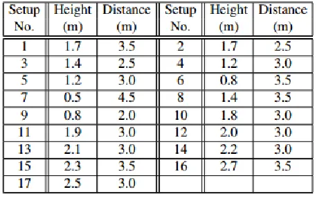
Table. 1 camera setups in the NTU RGB+D dataset
For the purpose of this paper, we are going to use only those camera setups, which are similar to the one used for experiments, hence selecting setups 2, 3, 8, 10. Future experiments will include all parts of the dataset, which will require view-normalization.
Fig.7. Activity sequences in the NTU RGB+D dataset
We select 5 activities – brushing teeth, clapping, wear a shoe, kicking something, make a phone call/answer phone, and perform key-point extraction analysis prior running the system. There are 23 key poses extracted for the selected activities. The test is executed with 3 people performing the activities, 5 times. The averaged results and the decision table for the experiment for each activity is shown on fig.8. We label the key points from the brushing teeth activity with K1, clapping with K2, wear a shoe key points – with K3, kicking something with K4 and make a phone call with K5. Sub-indexes refer to the original order from the dataset of the key-poses. The length of the activities is normalized so that it can be visualized. In pink color are shown the miss-classified key poses.
One key pose from the phone call activity K5R6R is replaced with a key pose from the
clapping activity K2R2R. Another 3 key poses
24
Fig.8. Key points decision table for the selected activities.
U
Conclusions:
This article proposes a system and algorithm for assessing the human pose using a multi-view camera system. Sequence selection of human pose is performed using a skeleton data provided by the Microsoft’s RGB-D sensor Kinect. The constructed system is using a few stationary calibrated Microsoft Kinect devices, giving the pose sequence estimation for each of the views. The system can segment complex human-made activity into a sequence of key poses derived from different views in 3D space.
Acknowledgement: This paper was
supported by Technical University – Sofia inner program to support PhD research projects under Contract № 162pd0025-7: “Human action estimation based on video image analysis”
U
References:
[1]. A. Shahroudy, J. Liu, T.-T. Ng, and G. Wang. NTU RGB+D: A Large Scale Dataset for 3D Human Activity Analysis. In The IEEE Conference on Computer Vision and Pattern Recognition (CVPR), 2016, pp. 1010-1019.
[2]. X. Yang and Y. Tian. Super Normal Vector for Human Activity Recognition with Depth Cameras. IEEE Transactions on Pattern Analysis and Machine Intelligence (TPAMI), 39(5) , 2017, pp. 1028-1039.
[3]. O. Oreifej and Z. Liu. HON4D: Histogram of Oriented 4D Normals for Activity Recognition from Depth Sequences. In 2013 IEEE Conference on Computer Vision and Pattern Recognition (CVPR), 2013, pp: 716–723.
[4]. R. Vemulapalli, F. Arrate, and R. Chellappa. Human Action Recognition by Representing 3D Skeletons as Points in a Lie Group. In 2014 IEEE Conference on Computer Vision and Pattern Recognition, 2014, pp. 588–595.
[5]. G. Evangelidis, G. Singh, R. Horaud, et al. Skeletal Quads: Human Action Recognition Using Joint Quadruples. In Proceedings of the 22nd International Conference on Pattern Recognition (ICPR 2014), 2014.
25
[7]. E. Ohn-Bar and M. M. Trivedi. Joint Angles Similarities and HOG2 for Action Recognition. In 2013 IEEE Conference on Computer Vision and Pattern Recognition Workshops (CVPRW), 2013, pp. 465–470.
[8]. Y. Du, W. Wang, and L. Wang. Hierarchical recurrent neural network for skeleton based action recognition. In 2015 IEEE Conference on Computer Vision and Pattern Recognition (CVPR), 2015, pp: 1110–1118.
[9]. M.E. Hussein, M. Torki, M.A. Gowayyed, M. El-Saban. Human action recognition using a temporal hierarchy of covariance descriptors on 3D joint locations. Proceedings of the Twenty-Third International Joint Conference on Artificial Intelligence, AAAI Press (2013), pp. 2466-2472
[10]. A. Yao, J. Gall, L. Van Gool. Coupled action recognition and pose estimation from multiple views. Int. J. Comput. Vis., 100 (1) (2012), pp. 16-37
[11]. L. Xia, C.-C. Chen, J. Aggarwal. View invariant human action recognition using histograms of 3D joints. Proceedings of the IEEE Conference on Computer Vision and Pattern Recognition Workshops, IEEE (2012), pp. 20-27
[12]. J. Wang, Z. Liu, Y. Wu, J. Yuan. Mining actionlet ensemble for action recognition with depth cameras. Proceedings of the IEEE Conference on Computer Vision and Pattern Recognition, IEEE (2012), pp. 1290-1297
[13]. E. Ohn-Bar, M.M. Trivedi. Joint angles similarities and HOG2 for action recognition. Proceedings of the IEEE Conference on Computer Vision and Pattern Recognition Workshops, IEEE (2013), pp. 465-470
[14]. R. Vemulapalli, F. Arrate, R. Chellappa. Human action recognition by representing 3D skeletons as points in a lie group. Proceedings of the IEEE Conference
on Computer Vision and Pattern Recognition, IEEE (2014), pp. 588-595.
[15] M. Hussein, M. Torki, M. Gowayyed, and M. El-Saban. Human Action Recognition Using a Temporal Hierarchy of Covariance Descriptors on 3D Joint Locations. In IJCAI, 2013, pp. 2468-2472.
[16] L. Xia, C. C. Chen, and J. K. Aggarwal. View Invariant Human Action Recognition Using Histograms of 3D Joints, In CVPRW, 2012, pp. 20-27.
[17] X. Yang and Y. Tian. Eigen Joints-based Action Recognition Using
Naıve-Bayes-Nearest-Neighbor. In CVPRW, 2012, pp. 14-19.
[18] Cippitelli, E., E. Gambi, S. Spinsante, Fr. Fl´orez-Revuelta, Evaluation of a skeleton-based method for human activity recognition on a large-scale RGB-D dataset, 2nd IET International Conference on Technologies for Active and Assisted Living, 2016, pp. 1-3.