ISSN (Print) : 2347 - 6710
I
nternational
J
ournal of
I
nnovative
R
esearch in
S
cience,
E
ngineering and
T
echnology
Volume 3, Special Issue 3, March 20142014
I
nternational
C
onference on
I
nnovations in
E
ngineering and
T
echnology (ICIET’14)
On 21st & 22nd March Organized by
K.L.N. College of Engineering, Madurai, Tamil Nadu, India
ABSTRACT— this paper deals with the damping of power system oscillations using the FACTS device Unified power flow controller (UPFC). This enhances the small signal angle stability. It combines the features of both static synchronous compensator (STATCOM) and static synchronous series compensator (SSSC). The main function of UPFC is power flow control and secondary functions are enhancement of small signal stability, transient stability, voltage control and oscillation damping. Firefly algorithm for optimizing the parameters of damping controller using Integral square error (ISE) technique has been implemented in this paper. Integral time absolute error also calculated. A single machine infinite bus system is considered for case study and it is implemented in MATLAB simulink. The Simulation results clearly indicate the effectiveness and validity of the proposed method.
INDEX TERMS—- Unified Power Flow Controller (UPFC), Single Machine Infinite Bus System (SMIB), Integral Square Error (ISE), Integral Time Absolute Error (ITAE).
I.INTRODUCTION
Due to rapid power demand and the expansion in generation and transmission is controlled with less availability of resources and due to environmental constraints, power systems are nowadays more complex than before. Low frequency oscillations are caused by remotely located power systems interconnection in the range of 0.2–3.0 Hz. If inadequate damping is provided, these oscillations may keep growing in magnitude until it loses its synchronism. In order to damp these power system oscillations and increase system stability UPFC based damping controller is used [1].
In recent years, the rapid progress in the field of power electronics had opened new chance for the FACTS devices
applications. The use of FACTS devices are the most efficient ways to improve power system operation
controllability and power transfer limits .By modulating the bus voltage, phase shift between buses, and transmission line reactance, FACTS devices can cause a considerable increase in power transfer limits during steady-state. Because of the tremendously fast control action associated with FACTS-device operations, they have been very commonly used for operation in power system damping enhancement [2]. An unified power flow controller (UPFC) is the most capable device in the FACTS concept. It has the ability to adjust the three control parameters, i.e. the bus voltage, Transmission line reactance and phase angle between two buses either simultaneously or independently [3].
II.UPFC:STRUCTURE AND OPERATION
UPFC consists of a series converter and a shunt converter connected by a common dc link capacitor as shown in figure 1.It can concurrently perform the function of transmission line real/reactive power flow control in addition to UPFC bus voltage/shunt reactive power control. The shunt converter of the UPFC controls the UPFC bus voltage/shunt reactive power and the dc link capacitor voltage. On the other hand the series converter of the UPFC controls the transmission line active power flows by injecting a series voltage of adjustable magnitude and phase angle.. The phase angle of series voltage can be chosen independently from line current between 0 and 2π, and its magnitude is variable between zero and a defined maximum value. The parallel part known as STATCOM injects an almost sinusoidal current of variable magnitude at the point of connection [4].
UPFC for Enhancement of Angle Stability
Using Optimization Technique
M.Jeyamurugan
#1, A.Nachammai
*2#1Department of Electrical and Electronics Engineering, K.L.N College of engineering,
madurai, India.
#2Department of Electrical and Electronics Engineering, K.L.N College of engineering,
Fig.1, Configuration of UPFC.
UPFC has four control inputs signals as
b e b
m , , me It offers major probable merits for the static and dynamic operation of transmission lines since it combines the features of both the Static Synchronous Compensator (STATCOM) and the Static Synchronous Series Compensator (SSSC). In this paper, an UPFC based controller is included to give the UPFC more flexibility and to increase its capability to damp the power system oscillations and to increase the life period of the UPFC controller.
III.ANGLE STABILITY
Stability is defined as the ability of the power system to return or regain its normal operating conditions after being subjected to some disturbances. If the disturbance is small it is called small signal stability and if it is large it is called large signal stability or transient stability. Angle stability deals with maintaining synchronism between generators.
Small signal stability is the capability of the power system to maintain synchronism under small turbulence. Such disturbances occur continually on the system because of small variation in load and generation.
Instability may result in two forms:
1.Steady increase in rotor angle due to lack of sufficient synchronising torque.
2.Rotor angle oscillation of increasing amplitude due to lack of sufficient damping torque.
For a generator connected radially to a large power system in the absence of Automatic voltage regulator(constant field voltage)the instability is due to lack of sufficient synchronising torque.
The nature of system response to small disturbances depends on a number of factors including the initial operating conditions, the transmisssion system strength, and the type of generator excitation controls used.The system is stable in the first swing but becomes unstable as a result of growing oscillations at the end state is approached.
IV.PHILIPS HEFFRON MODEL
Fig.2.Philips Heffron model of SMIB system
The synchronous machine is a fourth order model and a familiar Philips-Heffron block diagram of linearised model of the system. The relations among these variables are expressed in terms of the six constants K1-K6.
These constants with the exception of K3, which is only function of the ratio of impedance, are function of the operating real and reactive loading as well as the excitation levels in the machine. The linearised equations describing the given system are given below.
The equation below gives the state space form of the above model.
o
(
K
1
D
K
2
E
q)
is the rotor angle deviation
is the rotor speed deviationFrom the above block diagram the terminal voltage error signal which forms the input to voltage transducer is given by
Et K5
K6
fdThe coefficient K6 is always positive whereas K5 can be either positive or negative depending on the operating conditions and the external network impedance.
With automatic voltage regulator action the field flux variations are caused by the field voltage variations .
V. SMIB WITH INSTALLED UPFC
me mb
s
Consider the single machine infinite bus system with UPFC installed. UPFC is connected in the one of the parallel lines. This model permits the control of real and reactive power flow through a line. By controlling mb , the
magnitude of series injected voltage can be controlled. By controlling δb, the phase angle of series injected voltage
can be controlled, by controlling me, the output voltage of
the shunt converter can be controlled and by controlling δe ,
the phase angle of output voltage of the shunt converter can be controlled
VI.PHILIPS HEFFRON MODEL OF SMIB INCLUDING UPFC
UPFC
Fig.4.Philips Heffron model of SMIB including UPFC
A typical power system comprises a number of generating units connected to a set of loads through transmission lines.
The Figure shows the Philips Heffron model of the single machine infinite bus system including the voltage transducer and AVR/exciter blocks installed with UPFC. In this representation, the dynamic characteristics of the system are expressed in terms of the so-called K constants (K1-K6)
The control vector Fis defined as follows
e b
F Vdc m e mb T
Where
b
m
: Deviation in pulse width modulation index of series converter. By controlling me the
magnitude
of series injected voltage can be controlled.
b
: Deviation in phase angle of injected voltage.
e
m
: Deviation in pulse width modulation index of
shunt Converter.
e
: Deviation in phase angle of shunt inverter voltage.
The parameters Kp, Kq, Kvof unified power flow
controller are stated as given below.
] M K K M K M K M K [
Kp pd pe p pb M pb e ] ' T K ' T K ' T K ' T K ' T K [ K d0 d0 d0 q d0 qe d0 qd q b q qb e ] T K T K T K T K T K [ K A A A A A A A A A A
v Kvd Kve Kve Kvb Kve
VII.OBJECTIVE FUNCTION
The m a i n o b j e c t i v e i s t o minimize t h e r o t o r a n g l e deviation and rotor speed deviation thereby enhancing small signal angle stability. In this paper, Integral Square Error (ISE) Error of the rotor angle deviation (Δδ) is taken as the objective function. The parameters of UPFC are tuned by using Firefly algorithm. For the comparison, ITAE value is calculated by using the optimized parameters obtained by ISE for various conditions.
Minimize
J = ISE
K1min K1 K1max T1min T1 T1max T2min T2 T2max T3min T3 T3max T4min T4 T4max
The Integral square error is calculated as
shown
Below
ISE=
( 2(t)(dt) tsim
Where
tsim : Total simulation time period
T1, T2, T3, T4: Lead-Lag time constants
Ks is the gain constant
Typical ranges of the optimized parameters are [0.01– 100] for K and [0.01–1] for T1, T2, T3 and T4 +
+ +
1 2Hs+D
s
Kp Kq Kv
K2
do sT K3
1 + + + + + + 4
KKK46
VIII.FIREFLY ALGORITHM
Firefly-inspired algorithm can be developed by idealize some of the flashing characteristics of fireflies
The idealized rules are:
1. All fireflies are unisex so that one firefly will be attracted to other fireflies regardless of their sex.
2. Attraction is proportional to their brightness, thus for any two flashing fireflies, the less bright one will move towards the brighter one.
3. The attractiveness is proportional to the brightness and they both decrease as their distance increases. If there is no brighter one than a particular firefly, it will move randomly. The brightness of a firefly is determined or affected by the landscape of the objective function.
A. Light Intensity and Attractiveness:
The two important issues of Firefly algorithm are: 1. The variation of light intensity
2. Formulation of the attractiveness.
The brightness is associated with the encoded objective function. It will determine the attractiveness of firefly. The attractiveness must be judged by other fireflies as it vary with the distance between the firefly i and firefly j, as the distance from source increases the light is absorbed by the media. So the light intensity decreases so we should allow the attractiveness to vary with the degree of absorption.
According to the inverse square law, the light intensity is given by
2
)
(
r
l
r
I
Where is the intensity at source, For a given medium with a fixed light absorption coefficient γ, the light
intensity I varies with the distance r, that is r
o
e
I
I
As a firefly’s attractiveness is proportional to the light intensity, the attractiveness of a firefly is
2
r oe
The distance between the fireflies i and j is given by
r
i,j
(
x
i
x
j)
2
(
y
i
y
j)
2The movement of a firefly i is attracted to another more attractive firefly j is determined by
1
)
(
2
,
i jr o i
i
x
e
x
x
x
ijWhere the second term is due to the attraction and the third term is due to randomization.
IX.SIMULATION RESULT
To check the adequacy of UPFC damping controller simulation of the SMIB model of the power system is carried out by giving 10% change in voltage setting Vref
of the excitation system.
After simulation, the optimal parameters of the UPFC based controller using Fire Fly algorithm is given in table below.
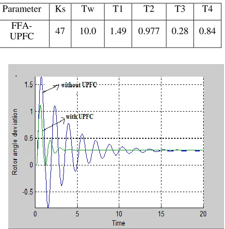
Parameter Ks Tw T1 T2 T3 T4
FFA-UPFC 47 10.0 1.49 0.977 0.28 0.84
Fig.5 Time response plot of Rotor angle deviation
Fig. 6Time response plot of Rotor speed deviation
X.CONCLUSION
and integral time absolute error also calculated. The objective is to minimize the rotor angle deviation and rotor speed deviation and to increase their damping. Based on the simulation result it can be concluded that UPFC provides better damping for a wide range of operating conditions.
REFERENCES
[1] H. Shayeghi , H.A. Shayanfar , S. Jalilzadeh and A. Safari , ― A PSO based unified power flow controller for damping of power system oscillations‖,Energy conversion and Management,2009.
[2] Gyugyi L.‖ Unified power-flow control concept for flexible
acTransmission systems‖. IEE Proc Gen Transm Distribution, pp.323–31,1992.
[3] Ali T. Al-Awami , Y.L. Abdel-Magid , M.A. Abido , ―A particle-swarm-based approach of power system stability enhancement with unified power flow controller‖,Electrical Power and Energy Systems 2007,pp 251–259.
[4] D. Murali and Dr. M.Rajaram, ―Active and reactive
powerflow control uaing FACTS devices‖, International journal of computer applications,vol.9,no.8,Nov 2010.
[5] P.Kundur,‖Power system stability and control‖ McGraw-Hill, New York,1994.
[6] Iztox Fister, Xin-She Yang, Janez Brest,―A comprehension review of Fire Fly algorithm‖, Elsevier, dec 2012.
[7] J.Usman, M.W.Mustafa, J.J.Jamian and G. Aliyu,‖Damping
low frequency oscillations in power systems using iteration particle swarm optimisations‖, ARPN journa l of
engineering appliedsciences,vol 7, No.11, Nov 2012.
[8] W.Du, H.F.Wang, S.Cheng, J.Y.Wen, R.Dunn., ―Robustness