Improvement
Components
of Structural Integrity Assessment Guideline
Part I : Evaluation of Defect-Free Structures
for Fast Reactor
Yukio Takahashi, Nobutada Ohno, Genki Yagawa
1) Central Research Institute of Electric Power Industry, Tokyo, Japan 2) Nagoya University, Nagoya, Japan
3) University of Tokyo, Tokyo, Japan
ABSTRACT
In the assessment of structural integrity of fast reactor plants, consideration of inelastic deformation is quite important because of high operating temperature exceeding 500°C. The authors have been developing a guideline for assessing long-term structural integrity of fast reactor components using detailed inelastic analysis and nonlinear fracture mechanics.
This guideline consists of two parts dealing with evaluation of defect-free structures and flawed structures. In the former,
use of advanced inelastic constitutive model and strain-based creep damage evaluation is recommended. Revision of the guideline was made in March, 2001 based on new test data and improvement of assessment methods. Outline of the revision for the first part is given in this paper, emphasizing the following two subjects:
(1) Modification of inelastic analysis method incorporating explicit consideration of interaction between plastic and creep deformation behavior.
(2) Modification of creep-fatigue damage evaluation method including reduction of safety factors and change of fatigue evaluation for welded joints.
I N T R O D U C T I O N
Development of fast reactor plants has been one of the targets with high priority for electric power generation industries in Japan and tremendous efforts have been made for developing technologies required for it. Because fast reactor plants are operated at higher temperatures than light water reactor plants, effects of time-dependent inelastic deformation and accompanying damage should be properly taken into account in the assessment of structural integrity of the components. The authors have been engaged in the development of structural integrity assessment methods using detailed inelastic
analysis and nonlinear fracture mechanics for fast reactor components [1-4]. The draft guideline was published in 1998
based on then available results of the study [5]. Afterwards, the study was continued in order to improve the reliability of
the guideline. In-sodium fatigue and creep-fatigue tests were performed for 3 ! 6FR steel, which is a main candidate for
structural material in primary cooling system. Based on their results and other works, the latest revision of the guideline
was made in March, 2001. This included modifications in inelastic constitutive model and in creep-fatigue damage
assessment for assessment of defect-free structures. This paper will present a outline of these modifications.
OUTLINE OF THE GUIDELINE
The guideline is named "Guideline for assessment of high-temperature structural integrity" and it consists of the following two parts.
(i) Evaluation of inelastic deformation and creep-fatigue damage for unflawed structures (ii) Evaluation of flawed structures
Then the former has the following chapters: (i) Scope of the guideline
(ii) Materials to be evaluated
(iii) Setup of loading condition for inelastic analysis (iv) Inelastic analysis method
(v) Evaluation of accumulated strain (vi) Evaluation of creep-fatigue damage
Because description of the details in inelastic analysis method is not given in (iv), the following two appendices are prepared:
(i) Recommended constitutive model
SMiRT 16, Washington DC, August 2001
Paper # 1426(ii) Incremental representation of constitutive model for finite element analysis (newly added)
M O D I F I C A T I O N O F I N E L A S T I C C O N S T I T U T I V E M O D E L
Outline of the Model
Classical plastic constitutive models such as isotropic hardening or linear kinematic hardening or model can not provide realistic descriptions for deformation behavior of engineering materials, especially under cyclic loading, and their application
to design assessment can bring about serious errors in regard to structural integrity. One of The authors [4] have been
developing a constitutive model which can describe inelastic deformation behavior of austenitic stainless steels precisely. Nonlinear kinematic hardening rule proposed by Ohno and Wang [6] was utilized as a basic framework of the model and
temperature-dependency as well as cyclic hardening was introduced to enhance the capability. The detail of the model can
be found in [4].
On the other hand, use of classical model based on strain-hardening rule was recommended for the prediction of creep
strain. However, full recovery of the hardening was simply assumed before each hold period, considering the effect of
reversed plastic deformation. This will gives us conservative estimates of creep strain and creep damage based on creep
strain. However, when reversed plastic deformation is absent or not as large as creep deformation, the method would be too
conservative. The following method was developed in order to improve the problem.
Creep-Hardening Surface and Its Evolution
The concept of creep-hardening surface was firstly proposed by Murakami and Ohno [7] and it was used as a basis of
the development. The surface is defined in creep strain space, as a group of points which satisfy the following equation:
_ ) ( 4 ) - : 0
where fl,) and Pc represent the center and the size of the surface and they are assumed to be zero initially.
It is then assumed that they change according to the following equations when creep deformation occurs:
when gc - 0 and ,'J(° ~c -,/7~ 1o ~c > 0 (creep strain is on the surface and creep strain rate is
(i)
] , J outward)j3~ - (1 - A)kkclnklnij (2a)
2 .c (2b)
h~ - ~/ 2~3 ,~ono
where nij is a tensor representing normal direction on the surface and given by
4.
/'l/j-/~k/j(sk/-/~kl)
(3)
/1 in eq. (2) gives a ratio of expansion and movement of the surface and /l =0.5 is recommended as the most
straightforward extension of the strain-hardening rule.
(ii) when gc < 0 or @ - riO ciJ < 0 (creep strain is inside the surface or creep strain rate is inward)
/5 c = 0 (4b)
Using these parameters and deviatoric stress, s!], equivalent accumulated creep strain to be substituted into a creep
strain equation can be evaluated by
,
(+; - p,; )++,
• } . ( s )
q =-22{pc +
x/C3 /2)SklSk]
In addition to the above equations already proposed by Murakami and Ohno [7], it is further assumed that fl,~ and Pc
change with plastic strain to take into account of the recovery of hardening by reversed plastic deformation. This was
achieved by using the following equations:
c c ) .,,+, > 0 (creep strain is on the surface and plastic strain rate is outward)
(i) when g c - 0 and oe,!-,/~;/ ~',! _
/~;. 0 (6a)
,O c = 0 (6b)
c c') "p
(ii) when gc - 0 and g,/-/6',! oe,/ < 0 (creep strain is on the surface and creep strain rate is inward)
fi';? • = - A , p , f / # n + ] n + / "P (7a)
(iii) when
gc
< 0 (creep strain is inside the surface)(8b)
where A,p is the constant representing the effect of recovery of hardening by plastic strain and the use of Ap - 0 . 5 is
recommended.
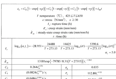
The creep strain equation for 316FR stainless steel recommended in the guideline is shown in Table 1. The equation has three primary creep strain terms in addition to the steady-state terms and can describe creep and relaxation behavior of the
material with a good accuracy [5]. The constant, c~., introduced to express heat-to-heat variation of creep deformation
Verification of tile Model
To verify the effectiveness of the model, creep deformation test periodically interrupted by load change was performed
at 600°C. Loading condition is shown in Fig. 1. Small loading rate of 0.1MPa/s was taken for the loading and unloading
phases in order to exclude the pseudo-plastic strain just after the start of holding. Measured and predicted creep
deformations in each hold period are shown in Fig. 2. After compressive loading accompanied by plastic strain, creep strain
rate became almost equal to the initial value at the initial loading and thus it is clear that creep hardening was fully recovered
by reversed plastic strain as an experimental result. On the other hand, small unloading and re-loading without plastic
deformation did not change the creep strain rate after restart of holding. Predictions by the present model for both situations
coincided well with these observations. This demonstrates the effectiveness of the present model in expressing the effect of
plastic deformation on creep deformation behavior. '
EVALUATION OF FATIGUE AND C R E E P DAMAGE
Outline of Evaluation Method
Accumulations of fatigue and creep damage are considered as principal failure modes in high-temperature components
of fast reactor plants. Based on this recognition, extensive creep-fatigue tests have been performed on 316FR steel and its
weldment. Number of creep-fatigue tests exceeded 100 and the longest test duration was 35,000 hours. Based on these
abundant data, applicability of life prediction methods has been studied [1-3]. The results by life prediction by ductility
exhaustion method and time fraction rule are shown in Fig. 3 [3]. It was found that creep-fatigue lives were considerably overestimated when the simple time fraction rule was used for creep damage evaluation, especially at small strain ranges of
practical interest. On the other hand, the ductility exhaustion method exhibited excellent capability of creep-fatigue life
prediction. Based on those observations, the ductility exhaustion method was employed as a basis of evaluation of creep
damage in the guideline. Conventional method based on cycle fraction was used fatigue damage evaluation and sum of two
damages is limited to unity.
Consideration on Safety Factors
Because of scattering of material property and other uncertainties, safety factors should be introduced in the design
assessment but too large values should be avoided because they may make proper component design difficult. Probabilistic
approach was taken in order to reconsider appropriateness of the safety factors. The database constructed by FME
Committee [8] based on the data from Japan Atomic Energy Company and Japan Nuclear Cycle Development Institute as well as the present study was utilized.
(1) Fatigue damage evaluation
Traditional safety factors used in fatigue damage assessment in the design of nuclear power plants have been 20 in terms
of life and 2 in terms of strain range or fictitious stress range. They were applied to the design of light water reactor plants
and succeeded to design codes for fast reactors as well as the present guideline. However, their appropriateness has not
been intensively examined so far.
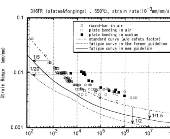
Results of Fatigue tests conducted at 550°C both in air and in sodium are plotted in Fig. 4 with standard fatigue curves
without and with safety factors. It can be seen that fatigue lives in sodium were much longer than those in air presumably
due to absence of oxidation effect in sodium. Moreover, many data at lower strain range showed longer life than the
standard curve, even for the results of in-air tests.
First, variation of fatigue failure life is analyzed by plotting the probability of the strain range ratio defined as
R~ = Ag~,,/Aa),,.~ (9)
where A~1,,. ~ is the strain range calculated using the fatigue life equation formally corresponding to mean property of the.
material, fi'om the actual fatigue life obtained by the fatigue test at the strain range, A~ex p . Distributions of the strain range
ratio for in-air test data and for in-sodium test data are shown in Fig. 5, independently. When excluding the data at smaller
strain range of in-air data, both data groups obeyed lognormal distribution function.
Also studied was the distribution of the applied strain range due to variation of cyclic deformation property. By using a
simple model considering elastic follow-up, distribution of the ratio of applied strain range was obtained as shown in Fig. 6, where lognormal distribution can apply.
(2) Creep damage evaluation
factor can be applied on it. Values of rupture elongation obtained in the creep tests at 550°(3 are plotted against rupture time
in Fig. 7. Although the rupture elongation decreased with increase in the rupture time up to about 1,000 hours but stayed
almost constant beyond that. Regression analysis gave us an almost constant value of 30% for the rupture elongation
beyond 1000 hours. Distribution of rupture elongation was characterized well by lognormal distribution as in the case of the
fatigue data (Fig. 8). Also considered were the variation of cyclic stress-strain curve which has an influence on initial stress
during holding, and that of creep deformation rate. The effects of these variations on creep strain decreases with the hold
time but those at the start of holding were taken for conservative evaluation of the failure probability.
s
(3) Result of evaluation
Failure probabilities evaluated according to those procedures are shown in Fig. 9 as a function of safety factor in terms
of strain range and creep ductility. Based on the in-sodium fatigue test data, safety factor of 1.5 was found to be sufficient
to make failure probability sufficiently small (less than 10 -1 i). On the other hand, safety factor of 3 on creep ductility would
be sufficient to suppress the creep failure probability to the same order.
According to these results, the safety factor was reduced and the fatigue curves were generated according to new safety
factors (see solid line in Fig. 4). Also the creep ductility used in creep damage evaluation was increased to 10% from 5%.
REVISION OF FATIGUE S T R E N G T H REDUCTION F A C T O R F O R W E L D E D J O I N T
Welded joints contain metallurgical inhomogeneity and need special attention in the assessment of structural integrity.
Fatigue strength reduction factors have been widely used to cope with this proble m practically. In the previous guideline,
no reduction factor was given for 316FR TIG welds, because weld metal and heat-affected zone have higher deformation resistance than base metal and failure occurred usually at base metal when welded joint specimens were tested by fatigue or
creep-fatigue loading. However, data at lower strain range were not sufficient.
Fatigue tests at low strain range were conducted for weld metal specimens in the last few years. Miniature specimens as well as standard size specimens cut from two welded joints were tested in strain control mode. Test results are shown in Fig.
10. Weld metal specimens showed fatigue lives considerably shorter than the base metal at low strain ranges and a factor in
terms of strain range reached about 1.6. Therefore, the fatigue strength reduction factor of 1.6 was introduced in the new guideline.
C O N C L U D I N G R E M A R K S
The guideline of structural integrity assessment for high-temperature components of fast reactor plants was updated.
Modifications were made on both inelastic analysis method and creep-fatigue damage evaluation. Consideration of effect of
reversed plastic strain on creep hardening would improve accuracy of creep damage evaluation for various loading conditions and reduction of the safety factors in damage evaluation would have a large effect on the design and construction costs of the
plants. Efforts will be continued to enhance the reliability of the guideline and to incorporate ferritic steels into the
guideline.
This study was carried out as a part of the project of the Ministry of Economy, Trade and Industry entitled "Verification
Tests of Fast Breeder Reactor Technology," which has been conducted since 1987. The authors would like to express their
sincere gratitude to the members of the advisory committee for the project.
R E F E R E N C E S
[1] Takahashi, Y., "Advancement of High-Temperature Structural Design Method for Fast Reactor Con iponents Part I : Creep-Fatigue Damage Evaluation Method for 316FR", ASME Book No. H01146, 1998, pp. 159-166.
[2] Takahashi, Y., "Evaluation of Creep-Fatigue Life Prediction Methods for Low-Carbon Nitrogen-Added 316 Stainless Steel", ASME Journal of Engineering Materials and Technology, Vol. 120, 1998, pp. 119-125.
[3] Takahashi, Y., "Further Evaluation of Creep-Fatigue Life Prediction Methods for Low-Carbon Nitrogen-Added 316 Stainless Steel", ASME Journal of Pressure Vessel Technology, Vol. 121, 1999, pp. 142-148.
[4] Takahashi, Y., "Advancement of High-Temperature Structural Design Method for Fast Reactor Components Part II : Inelastic Constitutive Model for 316FR", ASME Book No. H01146, 1998, pp. 167-174.
[5] Takahashi, Y., "Development of Structural Integrity Assessment Guideline for FBR Components", ASME Book No.
H01146, 1998, pp. 207-214.
and Basic Features for Rachetting Behavior", lilt. J. Plasticity, Vol. 9, 1993, pp. 375-390.
[7] Murakami, S. and Ohno, N., "A Constitutive Equation of Creep Based on the Concept of a Creep-Hardening Surface", Int. J. Solids and Structures, Vol. 18, 1982, pp. 597-609.
[8] FME Subcommittee, "316FR, Mod.9Cr-I Mo Steel Material Data", Japan Welding Association, 1999 (in Japanese).
Table 1 Standard Creep Strain Equation for 316FR
,c -c0{
exp(-rot)} +C 1 {1 exp(-q,)} +C 2 {1 exp(-,)t)} +ira t
T:temperature (0(2;), 425 < T < 6 5 0
o-:stress (N/mm2), o _-->30 t,. : rupture time (h) ~'c. : creep strain (mm/mm)
,£,,, : steady-state creep strain rate (mm/mm/h) t: time (h)
log,o (c~.t,.) = -28.951 + 24488 + 14425
loglo((7)
T+273.15 T+273.15
~', 13181 exp {-79785/8.3 I(T + 27315)} t,.
,~ ,-~,,- A • 0 370
Co
u.zo~,,,r °
C I ( 0 . t,.
u~z4~,,, )/11
. . . . 0 6 3 4r~
G
(0.0486L(,), ~ ) / ~
r 2
5390.6
T+ 2 - ~ i 5 {l°g'° (or)}2
~z c = 5.0
- 1 o865
0.035
112.80t,7 ° 921
39.391t,. -j°5
147MPa
~ o
-147MPa
Fig.2
A
B
0
100h
Condition of Creep Test with Periodic
Stress Changes
0.0014 0.0012 ~" 0.001
E
E o.o0o8
. . . . , ,
0.0006 O 0.0004 0 0002
0 20 40 60 80 O0
Hold time (h)
Fig. 3 Comparison of Predicted Creep
O ==
g
l.a.l c~ N-. 10 10 10 10 10 10... I ... I ... I ... I . . . . ~.-
~5°°016°0°c I
I
I
/ !
0 I @ I P i a t e A I
I/
;
5 13 I • I Plate B I V" "
z~ I "
IF0~g'ngl
/]
," ~
I x
I
PipeI/
I,"
,:
I I I / "1 ," "
5 t " . r I " V t l .i~
r a c { o r O T l a \ . / 1 _ x / z
I%o
~/U z"""
",'[
I
!
f a c t o r o f 3 0
: ... ; ... I ...
2 3 4 5 6
10 10 10 10 10 10
P r e d i c t e d number of c y c l e s to fa
(a) Time fraction rule
lure O 4-J (1) O O 4 - _ Q E ::3 c - m
- i J E (D E
D .
. - x I.,1.1 4 -
lO
lO
lO
lO 2 ~ lO
... I ... I
factor of 2 ~ . I , ~ O / / ]1
~ 7 1 550°c 600°c
/ / / u / I I [3 • Plate B
" / . "
I
I "
•
Forging/ ~ : , ... I ~ .. . . ,x ,~i~,e,,
2 3 4
10 10 10
P r e d i c t e d number of cycles to f a i lure
(b) Ductility exhaustion method
Fig. 3 C o m p a r i s o n of Predicted and E x p e r i m e n t a l Life in C r e e p - F a t i g u e T e s t s for 3 1 6 F R
E E E E v (D b.0 (-. c Y (..- L 4-1 ( / ' j
0.1
0.01
0 . 0 0 1
Fig. 4
316FR ( p l a t e s & f o r g i n g s ) , 5 5 0 ° C , s t r a i n r a t e 1 0 - 3 m m / m m / s
; ! . . . i . . . I . . . I . . . ! . . . ! . . .
: o round-bar in air
i [] plate bending in air
: / plate bending in sodium
,ko . . . . standard curve (w/o safety factor) ' \ ... fatigue curve in the former guideline "" ' " k fat i gue curve in new gu i de line
~,~/5
"~.
• ! " - _ . . , , ~ m~o o ~ ~ i
" ""- ... . , : - ~ ~ " - - ~ . . ooo
10 2 10 3 10 4 10 5 10 6 10 7 10 8
Number of C y c l e s t o Fai l u r e
> , _Q 0 13_ (1) 4J E 0 0 Fig. 9
9 9 . 9 9 . . . . . . . . . ~ . . . . . . . ; ...
5 0 0 ~ . 6 0 0 o c ,. :
9 9 . 9 . . . -r . . . ;,- . . . u /
/ 9 9 . . . -" .. . . I ! i / i ~ : ( % / 9 5 . . . /-'[ . . . 0 " . . .
9 0 - ! .t , .
8 0 . . . 6 ~- . . . 7 0 . . . ! . . . W o . . . 5 0 . . . -~.Q . . . 3 0 . . . o -Q . . . 2 0 . . . i . . . 0 . . .
o-!ii! !!!
...
. . . i . . . O"- . . . in-air t e s t d a t a (all) - ~ - - - in-air t e s t d a t a 1 - " ( e x c l u d i n g R o v e r 1 . 2 ) • 1 . . . ~-- . . . ;/~ . . . , ' © .... i n - s o d i u m t e s t d a t a (all)
. O l . . . . ~ . . . i _ _ _ ' _ _ . . .
0 . 5 0 . 6 0 . 7 0 . 8 0 . 9 1 2 RF. = A ~ e x b / A £ bre
Fig. 5 Distribution of Fatigue Strength in terms
of Strain
Range
• plate A [] plate B
100 I ! • Forging ! ! I ! !/ r ... ! ... ] ° l i t e r a t u r e data - - ! ! ! - ] 1 1
~- . . . i . . . . | - Regression for all d a t a ' i - i - i H
... i .... l . . . Regression for data beyond lO00h .--!.-~-[-i-{t
i ; . . . ; : ; : . . . ! i i ! i
/
--~ . . . . ! .... " - - - ! - [ - ' - 4 { - ' i . . . i .... 4---i--~-~,-;-,'--', -" . . . f .... 4---b-!-!-i-." ,:4
[ii[ii_o~ .... ~__~oi.__~.~.~i ... ! ... i.._~__i ... i_ii ... i .... i...i..i_i.i_i.i]
. . . . o , , , : ] : : q ~ . . .
I- . . . ~ ' ~ ... ~- .... ,~=---~---:: ... ,-=---~--',:,' ~q
' " i: ',: ;o ; ? ; ,,1,,:
...
... , .... i__.Li_!_!_i_Li ... _~_ ... ~°i~!,~i ° ', i ', ~
', ', l l l , , ,
! ! i ! i ! i !
iiii!ii i iii:,,i ,:,!':~:,,
10 i ; i i i i i l ~ ~ I ; i i ; i
10 2 103 04 105
Time t o R u p t u r e ( h )
Fig. 7 Variation of Creep Rupture Elongation
9 9 . 9 9
9 9 . 9
99 95 .~ 90 - - 80 -Q 70
c~ o 50 m • -a 3 0
~ 2 0 .4J
~ 10
m
E 5
o o
1 .1 .01
0.5 0.6 0.7 0.8 0.9 2
S t r a i n Range R a t i o
Fig. 6 Distribution of Strain Range due to
Variation of Cyclic Deformation Property
99.99 99.9
99 ... i ... L ... L..i...L_!._!_i_~ ... o .... i ... J ... ! .... L...i.--!--~-~
95
9o
8O
~ zo
-~ 5o
& ao
-~ 2o
~ 10
? s
.1
.01
O. 1 10
Rupture Elongation / Mean Value
Fig. 8 Distribution of Creep Rupture Elongation
T - d i r e c t i o n standard specimen (A) 1 0 0 ~ rl 0 T - d i r e c t i o n m i n i a t u r e specimen (A)
r l
| ~ ~ I Fatigue failure probability T - d i r e c t i o n standard specimen (B)
lO -1 I r ... ~ ... ! ... I (based on in-airtest data) t | 10 L - d i r e c t i o n standard specimen (A)
~ i I . . . Fatigue failure probability / | x Base metal
10-2 ~r . . . ~ - - ! ... I (basedoni . . . . dium test data) I | - Standard f a t i g u e curve for base metal
~ I . . . . Creep failure probability / | - - F a t i g u e curve f . . . ment of welded j o i n t
lO,
i:
- ~ 10-4 --
~o-~ ~
" ~ 10-6 b%
n L 10_ 7 ~. 1 _ .
E
::3 10-8 ~ . . . i . . . ':x . . . i . . . i . . . i . . . . . . i . . . :.~! . . . i--× . . . i : . . . X'X i . . . : 10-10
10-11 10-12
10-13 0.1
1 1.5 2 2.5 3 10 2 10 3 10 4 10 s 10 6 10 7 10 8
S a f e t y F a c t o r Number o f C y c l e s t o Fai l u r e