Reduction of MTTR in Grid Casting
Machine Heater Failures
C.Thanushree1, R.Thentamilelakiya2, D.Vedhashri3and P.Manivannan4
UG Scholar, Department of ECE, Adhiyamaan College of Engineering, Hosur, TN, India1,2,3 Associate Professor, Department of ECE, Adhiyamaan College of Engineering, Hosur, TN, India4
ABSTRACT: The project titled “REDUCTION OF MTTR IN GRID CASTING MACHINE HEATER
FAILURES”.In this project, the complex hardware circuitry usedis replaced by PLC(Programmable Logic Controller) which is programmed to control the motor drive, mould, ladle operation and temperature .By this method, Power consumption can be reduced and Productivity will be increased.This project provides benefits of MTTR reduction, the reduction in no. of. heater failures, Cost reduction, Man power reduction, Fatigue to the workmen reduction.
KEYWORDS: Mean Time To Repair(MTTR), Programmable Logic Controller(PLC)
I.INTRODUCTION
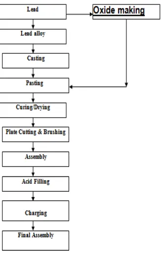
Fig 1: Process Flowchart
II.RELATEDWORK
DESCRIPTION OFLEAD ACID BATTERY
GRID CASTING
Grid production and parts casting involves like continuous casting, strip casting, etc. In these processes, lead bars are melted down and the molten lead is poured into molds or continuously cast into grids, strips or parts. The major source of lead exposure in this process is from lead fumes and lead oxide which can become easily airborne.
The grid is the skeleton of the plate. It is made of lead antimony alloy which is melted and poured into a mould. Pure lead is too soft and easily attacked by electrolyte; antimony is added to give stiffness and resistance to the action of electrolyte in the cell. Some manufactures cast two grids simultaneously in each mould the two plates being joined to each other along the bottom edge.
TRIMMING THE GRID
When the castings have cooled, they are removed from the moulds and passed to a trimming machine which trims off the casting gate and the rough edges. The grids are given a rigid inspection, those having shrunken or missing ribs or other defects being rejected. The grids are now ready for pasting.
APPLYING THE PASTE
DRYING THE PASTE
When the forming process is complete, the plates are washed and dried, and are then ready for use in the battery. If the grids of two plates have been cast together, as is done by some manufacturers, these are now cut apart, and the lugs cut to the proper height. The next step is to roll, or press the negatives after they are removed from the forming bath so as to bring the negative paste, which has become roughened by gassing that occurred during the forming process, flush with the surface of the ribs of the grid. A sufficient amount of sulphate is left in the plate to bind together the active material. Powder and when dry would fall out of the grids like dry dust. It shows a formed plate ready to be burned to the strap.
ASSEMBLING THE PLATE
In this process, all the parts are assembled into a battery case and covered with the plastic moulds, plastic moulding plant. This step involves the formation of positive and negative plate’s stacks, insertion of separators, inter cell connector and plate burning. In this step positive and negative plates are formed like groups which are strapped to a suitable rack, slipped together and separator is made up of non-conductive material such as paper, plastic or glass fiber.
During the burning operation each positive and negative plate tab is welded lead to produce an element and these are then welded to respective positive and negative post on the batteries case top. After keeping this element in the jar or case, sealing compound is applied to make the space leak proof between the battery jar and cover.
FORMING
The next process is to change the paste of oxides into the active materials which make a cell operative. This is called “forming”. In some factories the plates are mounted in tanks, positive and negative plates alternating as in a cell. The positives are all connected together in one group and the negatives in another, current passed through just as in charging a battery. In other factories the positives and negatives are formed in separate tanks against “dummy”electrodes. The passing of current slowly changes the mixtures of lead oxide and lead sulphate, forming brown peroxide of lead (PbO2), on the positive plate and gray spongy metallic lead on the negative. The
formation by the current of lead peroxide and spongy lead on the positive and negative plates would take place if the composition of the two pastes were identical.
III. EXISTINGSYSTEM
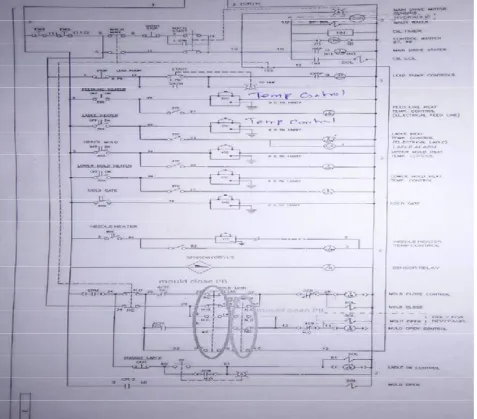
SCHEMATIC DIAGRAM OF EXISTING SYSTEM
EXPLANATION
In this existing system, the machine can be operated both in auto and manual conditions using auto switch and manual switch. In manual condition, motor runs until the start button is being pressed. Laddle does not engage during manual start. Mould open and close operations take place by the output of sensors provided. Mould opens only when sensor rays meet the main drive motor.
IV.PROPOSED SYSTEM
V.RESULT
The project is done successfully by reducing MTTR in grid casting machine heater failures. By doing this, the production rate is increased, consuming time is reduced, man power is highly reduced, high wiring is replaced by using PLC and defects are easily identified using HMI.
VI.CONCLUSION
In this project we have concluded that the heater failures in the grid casting machine has been reduced to a greater extent with the introduction of PLC which in turn reduces the time consumed to identify and rectify the faults and also increased productivity with reduced financial losses for the company. The interaction between humans and machines is made easier by the introduction of HMI which visually displays the failure occurred within the machine.
REFERENCES
[1] V.Märgner,H.El-Abed,P.Meinlschmidt,F.Schlüter“Quality ControlofInvisibleDefectsintheLaminatingProcessusinga NewThermo graphic Online System”IEEE 2007.
[2] Tae-KyunKima,HyunwooKima,WonjunHwanga,Josef Kittlerb“Component-basedLDA Face Description for Image Retrieval andMPEG-7Standardization”Feb2005.
[3] SindhuGhanta,TanjaKarpandSangwookLee,“WaveletDomain Detectionof RustinSteelBridgeImages”,IEEE 2011.