Available online: https://edupediapublications.org/journals/index.php/IJR/ P a g e | 4559
A Hybrid Power Generation With Solar and Wind System Using
Multi-Level Inverter
1M RAGHAVENDER, 2P.RAMU, 3M NIKITHA, 4B.DURGA NAIK 1B.TECH STUDENT TKR COLLEGE OF ENGINEERING & TECHNOLOGY Hyderabad, Telangana 2B.TECH STUDENT TKR COLLEGE OF ENGINEERING & TECHNOLOGY Hyderabad, Telangana 3B.TECH STUDENT TKR COLLEGE OF ENGINEERING & TECHNOLOGY Hyderabad, Telangana 4Associate Professor TKR COLLEGE OF ENGINEERING & TECHNOLOGY Hyderabad, Telangana
ABSTRACT
With the increasing concerns on energy
issues, the development of renewable energy
sources is becoming more and more
attractive.Anew kind of wind-PV hybrid
generated system that comprises of wind and
photovoltaic generation subsystems as input
to a cascaded H-bridge multilevel inverter is
developed in this paper. In conventional
methods the inverter with solar and wind
energy sources are used. In this method a
seven and three levelmultilevel inverter with
wind–PV hybrid generation system as input
are proposed for application to remote and
isolated areas. The wind and the solar light
are captured in greatest degree, as well as
the multilevel inverter using pulse width
modulation technique is adopted. The
objectives of this hybrid system are, to
satisfy the load power demand and, presence
of high number of output levels in inverter
to maintain the dc output voltage level of the
inverter to produce a nearly sinusoidal
output. This reduces harmonics in inverter
output voltage. This paper discusses about
the control of seven-level and three level
H-bridge cascaded multilevel inverter with
Fast Fourier Transform analysis in inverter
output voltage through simulation.
Key Words:
Cascaded H-Bridge, PWM, SPWM.
1. INTRODUCTION
Solar and wind are the renewable energy
sources. The solar and wind energy sources
are becoming more important since it
produces less pollution and the cost of fossil
fuel energy is rising, because of shortage of
fossil fuels and greenhouse effect. Now a
days , fossil fuel is the main energy supplier
of the world wide economy, but it is a major
cause of ecological problems (such as global
Available online: https://edupediapublications.org/journals/index.php/IJR/ P a g e | 4560
producing more energy combined with the
interest in green energy technologies results
in an increased development of power
distribution systems using renewable energy
sources (RES) such as wind energy, solar,
hydro, biomass, wave energy, tidal power
and geo thermal energy .
Among various types of renewable energy
sources, solar energy and wind energy have
become very popular and demanding due to
advancement in power electronic
techniques. Solar technologies tap directly
into the infinite power of the sun and use
that energy to produce heat, light and power.
Wind is one of the most environment
friendly, clean and safe energy resources.
The development of solar power generation
should be integrated with that of the wind
power generation systems since both forms
of renewable energy have inherently random
property and they can compensate the lack
of energy for each other. Hence, the wind
and solar power system therefore has higher
reliability to deliver continuous power than
either individual source.
The objective of this proposed project is to
propose a novel multilevel inverter using
hybrid solar and wind power system in order
to simplify the power system and reduce
harmonics and the cost effect. Multilevel
inverter using combination of solar and wind
was implemented by PWM modulation
technique. Pulse Width Modulation method
is a fixed dc input voltage is given to the
inverters and a controlled ac output voltage
is obtained by adjusting the on and off
periods of the inverter components. This is
the most popular method of controlling the
output voltage and in this method is known
as pulse width modulation (PWM
CONTROL). Which is confirmed by
MATLAB, the MATLAB is used to confirm
the seven level and three level output
voltage of inverter.
2. CONSTRUCTION AND WORKING
OF SOLAR AND WIND POWER
SYSTEMS
2.1 BLOCK DIAGRAM OF THE
PROPOSED PROJECT
Fig. 2.1 shows the block diagram of the
hybrid power generation system with solar
Available online: https://edupediapublications.org/journals/index.php/IJR/ P a g e | 4561
Fig 2.1 block diagram of a hybrid power
generation with solar and wind using multi
level inverter
The wind turbine is followed by a PMSG
generator, which generates an AC voltage
which is further rectified to DC voltage
through a rectifier unit. The input for the
inverter unit is taken from the DC link, the
dc link is given to multi level inverter. The
solar system generates a dc voltage. The
output of the solar is given to the multi level
inverter. The multilevel inverter is a device
which converts dc to ac output voltage. The
ac voltage is fed into utility.
The seven and three level cascaded H-bridge
multilevel inverter block with wind and
photovoltaic generation systems as input
sources block diagram is shown in Fig 2.1.
The block diagram consists of a solar panel,
wind energy system, full bridge DC-AC
inverter. The level dc voltage sources of
solar and wind are obtained from the solar
array and wind speed. The output from the
solar panel and rectified wind turbine ac
voltage is given to the multi level inverter.
By applying the Pulse-With-Modulation
(PWM) control scheme to the power
switches in the multi level inverter.
The solar array and wind turbine
simultaneously. Diode rectifier is used at the
wind output to convert ac power obtained
from wind module into dc power to be fed to
the multilevel inverter. Seven and three level
cascaded H-bridge inverter is used. The
voltage output of cascaded H-bridge
multilevel inverter is given to a resistive
load. The solar and wind power generation
system using Three-level cascaded H-bridge
inverter is similar to seven-level cascaded
H-bridge inverter.
3. CONTROL STRATEGY
3.1 Introduction to Pulse-Width
Modulation (PWM)
Pulse Width Modulation method is a fixed
dc input voltage is given to the inverters and
a controlled ac output voltage is obtained by
adjusting the on and off periods of the
inverter components. This is the most
popular method of controlling the output
voltage and in this method is known as pulse
width modulation (PWM CONTROL).
A modulation technique used to encode a
message into a pulsing signal. Although this
modulation technique can be used to encode
information for transmission, its main use is
Available online: https://edupediapublications.org/journals/index.php/IJR/ P a g e | 4562
electrical devices, especially to inertial loads
such as motors.
In addition, PWM is one of the two principal
algorithms used in photovoltaic solar battery
chargers, the other being maximum power
point tracking.
The average value of voltage (and current)
fed to the load is controlled by turning the
switch between supply and load on and off
at a fast rate. The longer the switch is on
compared to the off periods, the higher the
total power supplied to the load. The PWM
switching frequency has to be much higher
than what would affect the load (the device
that uses the power), which is to say that the
resultant waveform perceived by the load
must be as smooth as possible. The rate (or
frequency) at which the power supply must
switch can vary greatly depending on load
and application, for example the basic
concept behind multilevel inverter/converter
is to use low power rating devices instead of
high power rating devices to build up
medium voltage inverter system. The power
rating of devices used in the multilevel
inverter topologies is reduced, thereby
reducing the cost.
Sinusoidal Pulse width modulation
Sinusoidal Pulse Width Modulation
(SPWM) Figure 3.5 explains the generation
of a sinusoidal PWM signal, which finds
more applications in industries. the gating
signal can be generated by comparing a
sinusoidal reference signal with a triangular
carrier wave and the width of each pulse
varied proportionally to the amplitude of a
sine wave evaluated at the center of the
same pulse. The output frequency (fo) of the
inverter can be found by using the frequency
of the reference signal (fr).
Fig 3.5 Generation of Sinusoidal pulse width
modulation
4. SYSTEM OPERATION
4.1 OPERATION OF THE
MULTILEVEL INVERTER
The proposed three and seven level are load
connected MLI is an enhanced version of
the inverter. It consists one inverter is
connected in cascade. Fig 4.1 shows the
proposed hybrid power generation with solar
Available online: https://edupediapublications.org/journals/index.php/IJR/ P a g e | 4563
Fig 4.1 The proposed hybrid power
generation system with solar and wind using
multilevel inverter.
The solar system generates a dc voltage. The
output of the solar is given to the multilevel
inverter. The multilevel inverter is a device
which converts dc to ac output voltage. The
ac voltage is fed into utility. The wind
turbine is followed by a PMSG generator,
which generates an AC voltage which is
further rectified to DC voltage through a
rectifier unit. The input for the inverter unit
is taken from the DC link, the DC link is
given to multilevel inverter.
4.1.1 Operation of the proposed
seven-level multiseven-level inverter
Seven-level inverter is composed of a
capacitor selection circuit and a full-bridge
power converter, which are connected in
cascade. Operation of the seven-level
inverter can be divided into the positive half
cycle and the negative half cycle of the
utility. For ease of analysis, the power
electronic switches and diodes are assumed
to be ideal, while the voltages of both
capacitors C1 and C2 in the capacitor
selection circuit are constant and equal to
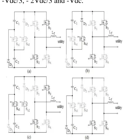
Vdc/3 and 2Vdc/3, respectively.
Fig 4.2 Operation of the proposed
seven-level multiseven-level inverter.
Since the output current of the solar and
wind power generation system will be
controlled to be sinusoidal and in phase with
the utility voltage, the output current of the
seven-level inverter is also positive in the
positive half cycle of the utility. The
operation of the seven-level inverter in the
positive half cycle of the utility can be
further divided into four modes, as shown in
Fig.4.3
Fig. 4.3 operation of seven-level inverter in
the positive half cycle, (a) mode 1, (b) mode
Available online: https://edupediapublications.org/journals/index.php/IJR/ P a g e | 4564
Mode 1
The operation of mode 1 is shown in Fig.
4.3 (a). Both SS1 and SS2 of the capacitor
selection circuit are off, so C1 is discharged
through D1 and the output voltage of the
capacitor selection circuit is Vdc/3. S1 and
S4 of the full-bridge power converter are on.
At this point, the output voltage of the
seven-level inverter is directly equal to the
output voltage of the capacitor selection
circuit, which means the output voltage of
the seven-level inverter is Vdc/3.
Mode 2
The operation of mode 2 is shown in Fig.4.3
(b). In the capacitor selection circuit, SS1 is
off and SS2 is on, so C2 is discharged
through SS2 and D2 and the output voltage
of the capacitor selection circuit is 2Vdc/3.
S1 and S4 of the full bridge power converter
are on. At this point, the output voltage of
the seven-level inverter is 2Vdc/3.
Mode 3
The operation of mode 3 is shown in Fig.
4.3(c). In the capacitor selection circuit, SS1
is on. Since D2 has a reverse bias when SS1
is on, the state of SS2 cannot affect the
current flow. Therefore, SS2 may be on or
off, to avoiding switching of SS2. Both C1
and C2 are discharged in series and the
output voltage of the capacitor selection
circuit is Vdc. S1 and S4 of the full-bridge
power converter are on. At this point, the
output voltage of the seven-level inverter is
Vdc.
Mode 4
The operation of mode 4 is shown in Fig.
4.3(d). Both SS1 and SS2 of the capacitor
selection circuit are off. The output voltage
of the capacitor selection circuit is Vdc/3.
Only S4 of the full-bridge power converter
is on. Since the output current of the
seven-level inverter is positive and passes through
the filter inductor, it forces the anti-parallel
diode of S2 to be switched on for continuous
conduction of the filter inductor current. At
this point, the output voltage of the
seven-level inverter is zero. Therefore, in the
positive half cycle, the output voltage of the
seven-level inverter has four levels: Vdc,
2Vdc/3, Vdc/3 and 0.
In the negative half cycle, the output current
of the seven-level inverter is negative. The
operation of the seven- level inverter can
also be further divided into four modes, as
shown in Fig.4.4. A comparison with Fig.
Available online: https://edupediapublications.org/journals/index.php/IJR/ P a g e | 4565
selection circuit in the negative half cycle is
the same as that in the positive half cycle.
The difference is that S2 and S3 of the
full-bridge power converter are on during modes
5, 6 and 7, and S2 is also on during mode 8
of the negative half cycle. Accordingly, the
output voltage of the capacitor selection
circuit is inverted by the full-bridge power
converter, so the output voltage of the
sevenlevel inverter also has four levels:
-Vdc, -2Vdc/3, -Vdc/3 and 0. In summary,
the output voltage of the seven-level inverter
has the voltage levels: Vdc, 2Vdc/3, Vdc/3,
0, -Vdc/3, - 2Vdc/3 and -Vdc.
Fig. 4.4 operation of seven-level inverter in
the negative half cycle, (a) mode 5, (b) mode
6, (c) mode 7, (d) mode 8.
The seven-level inverter is controlled by the
current mode control, and pulse-width
modulation (PWM) is use to generate the
control signal for the power electronic
switch.
Fig. 4.5 model of seven-level inverter under
different range of utility voltage,(a) in the
range of smaller than Vdc/3, (b) in the range
of (Vdc/3, 2Vdc/3), (c) inthe range of higher
than 2Vdc/3.
4.1.2 Operation of the proposed
three-level multithree-level inverter
The cascaded H-bridge inverter has drawn
tremendous interestdue to the greater
demand of medium-voltage high-power
inverters. Itis composed of multiple units of
Available online: https://edupediapublications.org/journals/index.php/IJR/ P a g e | 4566
Fig 4.7 Operation of the proposed
three-level multithree-level inverter.
The H-bridge cells are normally connected
in cascade ontheir ac side to achieve
medium voltage operation and lowharmonic
distortion .The single phase H-bridge cell,
which is thebuilding block for the cascaded
H-bridge inverter is associatedwith separate
dc source.
SIMULATION RESULTS
fig 5.1 simulation model of hybrid power generation using
seven-level inverter
Table 5.1 Parameters of Hybrid Power Generation Using
Seven-Level Inverter
Seven –level inverter
Solar cell
temperature
25ºC
Wind turbine
speed
12 m/s
Capacitor 𝐶1, 𝐶2 1000µF
PWM frequency 15360 Hz
Output voltage of inverter
600V
Output current of inverter
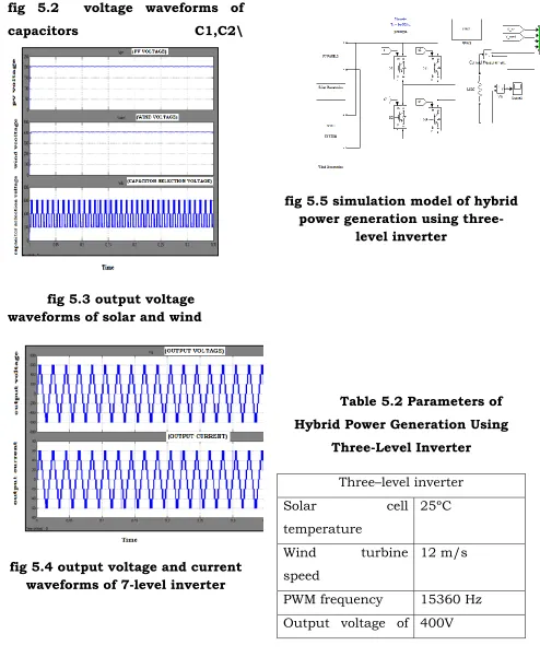
Available online: https://edupediapublications.org/journals/index.php/IJR/ P a g e | 4567 fig 5.2 voltage waveforms of
capacitors C1,C2\
fig 5.3 output voltage waveforms of solar and wind
fig 5.4 output voltage and current waveforms of 7-level inverter
fig 5.5 simulation model of hybrid power generation using
three-level inverter
Table 5.2 Parameters of Hybrid Power Generation Using
Three-Level Inverter
Three–level inverter
Solar cell
temperature
25ºC
Wind turbine
speed
12 m/s
PWM frequency 15360 Hz
Available online: https://edupediapublications.org/journals/index.php/IJR/ P a g e | 4568 inverter
Output current of inverter
0.8A
fig 5.5 output waveforms of hybrid system using Three-level
inverter
CONCLUSION
In this proposed project seven and three
level cascaded H-bridgemultilevel inverter is
used to get sinusoidal stepped output
waveform, it is used to also reduces the
harmonics in output voltage and theoutput
results of both inverters are compared by
using theMATLAB/SIMULINK.The seven
and three level cascaded H-bridgemultilevel
inverter fed by solar and wind energy source
have beenillustrated in simulation results by
using MATLAB. Many people livein
isolated areas far from the main utility grid.
In such remote orisolated areas, the
wind-solar hybrid generation system is
particularlyvaluable and attractive. Since the
cost of conventional energyresources are
increasing every year, this system is going to
beeconomical in future. Besides the cost, the
environmental benefits arelikely to facilitate
the widespread use and acceptance of this
system.Thus the above proposed system is
reliable and economical for
remoteapplications.
REFERENCES
[I]. M. Murugesan, K. Ramani and S.
Thangavel "A Hybrid MultilevelInverter
with Reduced Number of Switches for
Induction Motor Drive"African Journal of
Scientific Research Vol. 4, No. 1 2011.
[2]. K. Ramani and A. Krishnan "New
Hybrid 27 Level MultilevelInverter fed
Available online: https://edupediapublications.org/journals/index.php/IJR/ P a g e | 4569
Journal of RecentTrends in Engineering, Vol
2, No. 5, November 2009.
[3]. Abu Tariq, Mohammed Aslam Husain
and Mohammad Ahmad,Mohd.
Tariq"Simulation and study of a grid
connected MultilevelConverter (MLC) with
varying DC input" IEEE 2011.
[4]. Altas T. H, and Sharaf A. M, "A
Photovoltaic Array SimulationModel for
Matlab-Simulink GUI Environment" IEEE
2007.
Authors
1M RAGHAVENDER, B.TECH STUDENT TKR COLLEGE OF ENGINEERING & TECHNOLOGY
Hyderabad, Telangana
2P.RAMUB.TECH STUDENT TKR COLLEGE OF ENGINEERING & TECHNOLOGY Hyderabad, Telangana
M NIKITHA B.TECH STUDENT TKR COLLEGE OF ENGINEERING & TECHNOLOGY Hyderabad, Telangana
B.DURGA NAIK Associate Professor TKR COLLEGE OF ENGINEERING & TECHNOLOGY Hyderabad,