APPLICATION OF ARRAY PROCESSING
TECHNIQUES IN MULTIBASELINE INSAR FOR HIGH-RESOLUTION DEM RECONSTRUCTION
Z. J. Mao and G. S. Liao
National Key Laboratory of Radar Signal Processing Xidian University
Xi’an 710071, P. R. China
Abstract—This work is concerned with generating the digital elevation models (DEMs) from the SAR images of the region of interest using multiple sensor arrays that are fixed on the distributed satellites. We present an exact estimate of the unwrapped phase and the relationship between the unwrapped phase and the terrain height. The optimum scheme that jointly processes the signals from all sensors is based on the model of the multibaseline joint block vector. The method can simultaneously coregister the SAR images, phase unwrapping and DEM generation in the presence of the large coregistration errors. The performance of our approach is verified by a series of simulation experiments based on the distributed sensor arrays.
1. INTRODUCTION
multibaseline InSAR system is widely exploited to combine the array processing technique for facilitating phase unwrapping and high-quality DEM reconstruction in the literature [4–10].
In InSAR data processing for the generation of the DEM of a terrain, image coregistration is likewise a fundamental task in image processing used to match two or more SAR images [11–13]. However, when the required coregistration accuracy is not reached, the obtained interferometric phase will be too noisy to be unwrapped due to the coregistration error. Accordingly, it is necessary to find a registration strategy robust to the large coregistration error to unwrap the terrain interferometric phase.
Phase-to-height conversion is a very important step in the DEM generation procedure. Therefore, the relationship between phase and height should be calculated accurately. Successful phase-to-height conversion requires relative orbital parameters accuracy [14] and a fulfillment of the basic requirements for the InSAR system. These requirements consist of, first, stable atmospheric conditions and terrain backscatter and, second, the same InSAR geometry. In this paper, we propose a robust phase unwrapping method and an exact relationship of the unwrapped phase and the terrain height. The essence of the phase unwrapping method is based on the combination joint pixel approach, array processing technique and optimization algorithm, which is quite different from that of the interferogram filtering. The optimum scheme that jointly processes the signals from all sensors is based on the multibaseline joint block vector. Moreover, we present the general and exact formulation between the interferogram phase and the target height which is based on the interferometric SAR geometry. Based on this idea, the paper is arranged as follows: Section 2 presents signal model and unwrapped phase estimation. In Section 3, we formulate the relationship between the interferometric phase and the height profiles. The performance of the method is investigated with simulated data in Section 4. The conclusions are in Section 5. 2. UNWRAPPED PHASE ESTIMATION
2.1. Signal Model and Problem Statement
be modeled as
x(i) =a(ϕi)s(i) +n(i) (1)
where x(i) = [x1(i), x2(i),· · ·, xM(i)]T denotes the complex data
vector, which can be modeled as a joint zero-mean complex circular Gaussian random vector [15, 16],s(i) = [s1(i), s2(i),· · ·, sM(i)]T is the
complex magnitude vector (i.e., the complex reflectivity vector received by the satellites), and n(i) is the additive noise term, the superscript T stands for vector transpose, anddenotes the element-wise Schur-Hadamard product. Furthermore,
a(ϕi) =
ej(m−1)ϕi/(M−1)M
m=1 (2)
represents the array steering vector (or the spatial steering vector) of the pixel pair i, and ϕi is an unknown deterministic parameter
representing the unwrapped phase for theith examined resolution cell, i.e., the phase difference between the two furthest phase centers in the array.
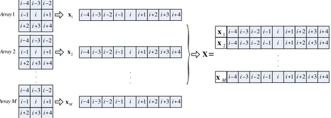
For the convenience of presenting the proposed method, as shown in Fig. 1, where rectangles represent the SAR image pixels, and i is the centric pixel pair (i.e., the desired pixel pair whose absolute phase is to be estimated). When we construct the joint complex pixel vector, the selection of the pixel window sizes is tradeoff between the computational complexity and the lack of enough samples to estimate the covariance matrix. In this paper, we propose the combination processing approach to estimate unwrapped phase. The proposed method can provide the robust unwrapped phases even in the presence of the large image coregistration errors, and has the ability to overcome the conflict associated with the computational complexity and the lack
1 i i i1
2 i i3i 4
2 i 3 i 4 i 2 i 3 i 4
i i1 i i1i 2i3i4
1 i i i1
2 i i3i 4
2 i 3 i 4 i 1 i i i1
2 i i3i 4
2 i 3 i 4 i 2 i 3 i 4
i i1 i i1i 2i3i4
2 i 3 i 4
i i1 i i1i 2i3i4 2 Array 1 Array Array M 2 i 3 i 4
i i1 i i1i 2i3i4 2
i 3 i 4
i i1 i i1i 2i3i4
2 i 3 i 4
i i1 i i1i 2i3i4
1 x 2 x M x 1 x M x 2 x X − − − − − − − − − − − − − − − − − − − − − − − − − − − − − − − − − − − − + + + + + + + + + + + + + + + + + + + + + + + + + + + + + + + + + + + + . . . . . . . . . =
of the independent and identically distributed (i.i.d.) samples. As shown in Fig. 1, we define the multibaseline joint block vector as
X(i) = [x1(i),x2(i),· · · ,xM−1(i),xM(i)]T (3)
and
xm(i) = [xm(i−4),· · ·, xm(i),· · ·, xm(i+ 4)], m= 1,2,· · ·, M (4)
By using Equations (3) and (4) one can write the corresponding joint covariance matrixCX(i) as follows:
CX(i) = E[X(i)X(i)∗]
= σx2(i)A(ϕi)A∗(ϕi)RS(i) +σn2I (5)
whereRS(i) is called the joint correlation coefficient matrix of the pixel
pair i. In the sense of statistical expectation, RS(i) = E[s(i)s(i)∗]
does not contain the noise components, which means that it only has signal components. I is an M×M identity matrix, and E[·] denotes the statistical expectation operator, the superscript ∗ denotes vector conjugate-transpose,σx2(i) is the echo power of the pixel pairiand σ2n is the noise power. And
A(ϕi) = [a(ϕi−4),a(ϕi−3),· · ·,a(ϕi),· · ·,a(ϕi+4)]T (6)
For simplicity and without loss of generality, we assume that the neighboring pixels have an identical terrain height, then we have the following expression for the array steering vector:
a(ϕi−4) =a(ϕi−3) =· · ·=a(ϕi) =· · ·=a(ϕi+4). (7)
From Equations (6) and (7), we can see thatAis a Vandermonde matrix, and AA∗ is a Hermitian matrix. Consequently, the beamforming problem is formulated as follows:
P=a∗(ϕi)CX(i)a(ϕi) (8)
The maximum output provides an estimate of the signal power and the unwrapped phase estimate is given by the scan value of ϕi that
achieves this maximum, namely P = a∗(ϕi)
σ2xA(ϕi)A∗(ϕi)RS(i) +σn2I
a(ϕi)
= M·σ2xa∗(ϕi)RS(i)a(ϕi) +σn2I
σx2(i), RS(i) and σn2. A possible candidate is a maximum likelihood
estimation. However, although the corresponding likelihood function can be easily written down. Its maximization results are tremendously burdensome, and the maximization problem is multidimensional and nonconvex. Therefore, we should resort the other approaches to estimate the unwrapped phase. In this paper, we exploit the robust beamforming approach [17–21] to estimate the unwrapped phase. 2.2. Phase Unwrapping
If the SAR images are accurately coregistered, the construction of the multibaseline joint block vector X(i) is shown above in (3). The corresponding sample covariance matrix is given by CX(i) in (5). In practice, the coregistration error always exists in the SAR images, thus the construction of the weighted multibaseline block vectorX(i,wopt)
can be written as X(i,wopt) =
ˆ x1
i,w(1)opt
,xˆ2
i,w(2)opt
,· · ·,ˆxM
i,w(optM)
T (10) where ˆ xm
i,wopt(m)=[ˆxm(i−4),· · ·,xˆm(i),· · ·,xˆm(i+4)], m= 1,2,· · ·, M(11)
ˆ
xm(k)=w(optm)∗xTm(k), k=i−4, i−3,· · ·, i,· · ·, i+4 (12)
wopt is the optimal weight vector, which is developed in [22, 23].
The corresponding covariance matrix CX(i,wopt), in fact, can be
estimated by the sample covariance matrixCXˆ (i,wopt) in (13) of the
independent and identically distributed samples. ˆ
CX(i,wopt) =
1 2K+ 1
K
k=−KX(i+k,wopt)X
∗(i+k,w
opt) (13)
where 2K+1 is the number of i.i.d. samples from the neighboring pixel pairs. According to the RMB rule [24], the number of i.i.d. samples of 2K+ 1 ≥ 2M −1 would make the estimation loss within 3 dB if the dimensions of the sample covariance matrix areM×M.
Using (13), the unwrapped phase estimation can be obtained by using the robust beamforming as
ˆ
ϕunwrap= arg max
ϕi
a∗(ϕi)·CXˆ (i,wopt)·a(ϕi)
(14) The maximum in (14) corresponds to the estimate of the absolute interferometric phase, i.e., ˆϕunwrap= the maximumϕi.
3. PHASE TO HEIGHT CONVERSION
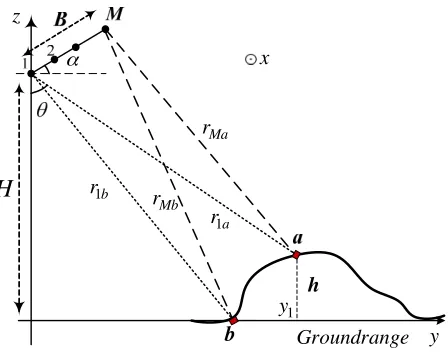
Consider the InSAR system geometry shown in Fig. 2, SAR receivers are aligned in abaseline B oriented at an angleα with respect to local horizontal. The slant ranges r1a and rM a to a scatterer a at height
z = h and ground range y1 are measured independently at the two
furthest receive apertures. The positive x coordinate (not shown) is normal to the page, toward the reader.
1a r 1b
r
Groundrange y
z
x
1 y
H
Ma r
Mb r
b
h α
Figure 2. Form of the InSAR system geometry.
Assuming r1a B, the difference in received phase at the two
furthest phase centers becomes ϕreal =
2π λ ∆r =
2π
λ (rM a−r1a) = 2π
λ r
2
1a+B2+ 2Br1asin(θ−α)−r1a
∼ = 2π
λ r1a
1 + 2 B r1a
sin(θ−α)−1
∼ = 2π
λ Bsin(θ−α) (15)
where r1a =
(H−h)2+ (y1)2. Since the obtained interferometric
phases are flattened with a reference plane surface of zero height, then the unwrapped phase of the resolution element can be written as
= 2πB λ
sin(θ−α)− 1 1 + (H/y1)2
(16)
where ϕf lat = 2πB λ√1+(H/y1)2
is flat-earth phase which depends on the scatterer’s ground range y1 but not on its cross- range coordinate x,
at least for the sidelooking scenarios considered here. We have
θ= sin−1
ϕunwrapλ
2πB +
1
1 + (H/y1)2
+α (17)
Accordingly, the scatterer height is then obtained easily as
h=H−y1/tanθ. (18)
We obtain the unwrapped phase at each point in an image and apply Equations (17) and (18) to produce the topographic height of a terrain.
4. PERFORMANCE INVESTIGATION
In this section we evaluate the performance of the proposed method. Assuming a multibaseline cross-track interferometer system with six two-dimensional phase centers aligned to form a uniform linear array. We use a real SAR image to generate the reflectivity of each SAR pixel and simulate the mountainous terrain. The signal-to-noise ratio (SNR) of the SAR images is 17 dB and the correlation coefficient of each pixel pair is computed according to the cross-track baseline length, the local terrain slope and the SNR [15, 16].
covariance matrix in [25] are 9 times that of the proposed method. Furthermore, the dimensions of the covariance matrix of the proposed method only relate to the number of the array phase centers and are uncorrelated with how to choose the pixel window sizes to construct the multibaseline joint block vector. Accordingly, we can conclude that the overall computational cost of the proposed method is much lower than that of the joint subspace method.
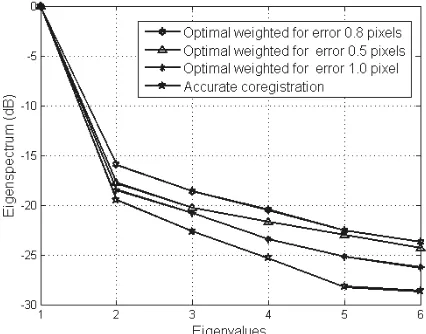
To help understand the model of the multibaseline joint block vector, we discuss first the eigenspectra of the covariance matrix for different coregistration errors. In Figs. 3, and 4, we plot the eigenspectra of the covariance matrix for the different coregistration errors (the coregistration errors of the mth (m = 2,3,· · ·,6) SAR images with respect to the first SAR image). Fig. 3 is the eigenspectra of the covariance matrix for coregistration errors of [0.5, 0.8, 1.0] pixels, respectively. Fig. 4 shows the eigenspectra for accurate coregistration and coregistration errors of [0.5, 0.8, 1.0] pixels after the optimization on the radar echo using the proposed method. From Figs. 3 and 4, we can observe that the phase noise is suppressed greatly by the proposed method.
Figure 3. Eigenspectra of joint covariance matrix for different coregistration errors using the conventional method.
Figure 4. Eigenspectra of joint covariance matrix for different coregistration errors using the proposed method.
Figure 5. Unwrapped phase computed with the robust adaptive beamforming.
phase in the presence of the large coregistration errors.
To further verify the robustness of the proposed method to the different image coregistration errors, we reconstruct the DEM of the terrain via the obtained unwrapped phase. In the case of accurate coregistration of the six SAR images, Fig. 6(a) is the reconstructed DEM of the terrain by using the conventional processing. Fig. 6(b) is the height error map between the reconstructed DEM and the originally simulated terrain. Figs. 7(a) and 7(b) plot the reconstruction of the terrain and the height error map in the presence of coregistration error of 0.5 pixels using the conventional processing, respectively. When the image coregistration errors reach one pixel, the interferogram obtained by the conventional processing is very noisy.
Figure 8 shows the case of accurate coregistration between the
(a) (b)
Figure 6. Results by the conventional method for accurate coregistration: (a) Reconstructed terrain, (b) Height error.
(a) (b)
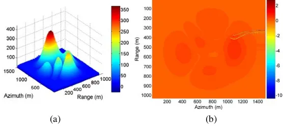
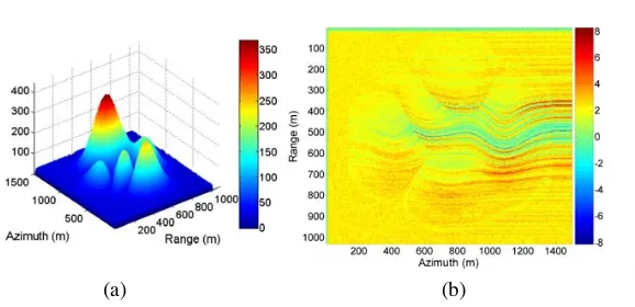
SAR images, where Fig. 8(a) is the reconstructed terrain by the proposed method, Fig. 8(b) is the height error map between the reconstructed terrain and the originally simulated terrain. Figs. 9(a) and 9(b) plot the reconstructed DEM and the height error map in the presence of coregistration error of 0.5 pixels using the proposed method, respectively. When the image coregistration errors reach one pixel, the corresponding pixel pairs are completely decorrelated, and the proposed method can still accurately estimate the unwrapped phases, as shown in Fig. 10. On the contrary, there are no interferometric fringes in the interferogram obtained by the conventional processing. Comparing Figs. 8–10 with Figs. 6 and 7, we can observe that the large coregistration error has almost no effect on the interferogram obtained by the proposed method. The results from Figs. 8–10 manifest that the
(a) (b)
Figure 8. Results by the proposed method for accurate coregistration: (a) Reconstructed terrain, (b) Height error.
(a) (b)
(a) (b)
Figure 10. Results by the proposed method for coregistration error of 1.0 pixels: (a) Reconstructed terrain, (b) Height error.
method can provide the accurate reconstruction of the height profiles in the presence of the large image coregistration errors.
5. CONCLUSIONS
The optimum scheme that jointly processes the signals from all sensors has been studied. Behavior under the multibaseline joint block vector, for the phase unwrapping and the phase-to-height conversion are regarded in the presence of the large image coregistration errors. Moreover, the method has the ability to overcome the conflict associated with the computational complexity and the lack of the independent and identically distributed samples. Theoretical analysis and experimental results show that the proposed method can provide the accurate estimation of the height profiles in the presence of the large coregistration errors.
ACKNOWLEDGMENT
The work was supported by the National Nature Science Fund of China (No. 60736009).
REFERENCES
2. Xu, W. and I. Cumming, “A region-growing algorithm for InSAR phase unwrapping,”IEEE Trans. Geosci. Remote Sens., Vol. 37, No. 1, 124–134, 1999.
3. Goldstein, M., H. A. Zebker, and C. L. Werner, “Satellite radar interferometry: Two-dimensional phase unwrapping,”Radio Science, Vol. 23, 713–720, 1988.
4. Ghiglia, D. C. and D. E. Wahl, “Interferometric synthetic aperture radar terrain elevation mapping from multiple observations,”
Proc. 6th IEEE Digital Signal Process. Workshop, 33–36, Albuquerque, NM, 1994.
5. Martorella, M. and B. Littleton, “Multibaseline cross-track SAR interferometry using interpolated arrays,” IEEE Trans. Aerosp. Electron Syst., Vol. 41, No. 4, 1472–1481, 2005.
6. Kim, M. G. and H. D. Griffiths, “Phase unwrapping of multibaseline interferometry using Kalman filtering,” Proc. 7th IEE Int. Conf. Image Process. and Appl., 813–817, London, U.K., 1999.
7. Fornaro, G., A. M. Guarnieri, et al., “Maximum likelihood multi-baseline SAR interferometry,” Proc. IEE-Radar Sonar Navig., Vol. 153, No. 3, 279–288, 2006.
8. Ferretti, A., C. Prati, and F. Rocca, “Multibaseline InSAR DEM reconstruction: The wavelet approach,” IEEE Trans. Geosci. Remote Sens., Vol. 37, No. 2, 705–715, 1999.
9. Qu, Y., G. S. Liao, S. Q. Zhu, and X. Y. Liu, “Hybrid array antenna for broadband millimeter-wave applications,”Progress In Electromagnetics Research, PIER 84, 1–10, 2008.
10. Li, W. T. and X. W. Shi, “An improved particle swarm optimization algorithm for pattern synthesis of phased arrays,”
Progress In Electromagnetics Research, PIER 82, 319–332, 2008. 11. Zitova, B. and J. Flusser, “Image registration methods: A survey,”
Image and Vision Computing, Vol. 21, No. 11, 977–1000, 2003. 12. Brown, L. G., “A survey of image registration techniques,”ACM
Computing Surveys, 326–376, 1992.
13. Scheiber, R. and A. Moreira, “Coregistration of interferometric SAR images using spectral diversity,” IEEE Trans. Geosci. Remote Sens., Vol. 38, No. 5, 2179–2191, 2000.
14. Moccia, A., S. Esposito, and M. Derrico, “Height measurement accuracy of ERS-1 SAR interferometry,” EARSel Adv. Remote Sens., Vol. 3, No. 1, 94–108, 1994.
interferometry,”Proc. IEEE, Vol. 88, No. 3, 333–382, 2000. 16. Bamler, R. and P. Hartl, “Synthetic aperture radar
interferome-try,”Inv. Prob., Vol. 14, 1–54, 1998.
17. Lorenz, R. G. and S. P. Boyd, “Robust minimum variance beamforming,”IEEE Trans. Signal Process., Vol. 53, No. 5, 1684– 1696, 2005.
18. Vorobyov, S., A. B. Gershman, et al., “Robust adaptive beamforming using worst-case performance optimization: A solution to the signal mismatch problem,” IEEE Trans. Signal Process., Vol. 51, 313–324, 2003.
19. Zhang, X. and D. Xu, “Deterministic blind beamforming for electromagnetic vector sensor array,”Progress In Electromagnetics Research, PIER 84, 363–377, 2008.
20. Panduro, M. A., “Design of beam-forming networks for scannable multi-beam antenna arrays using corps,” Progress In Electromagnetics Research, PIER 84, 173–188, 2008.
21. Gu, Y. J., Z. G. Shi, and K. S. Chen, “Robust adaptive beamforming for a class of gaussian steering vector mismatch,”
Progress In Electromagnetics Research, PIER 81, 315–328, 2008. 22. Mao, Z. J., G. S. Liao, et al., “InSAR interferometric phase
estimation based on optimum data vector,” Submitted to Proc. IET - Radar Sonar Navig.
23. Mao, Z. J., G. S. Liao, et al., “Optimum data vector approach to multibaseline SAR interferometry phase unwrapping,” IEEE Geosci. Remote Sens. Letts., Submitted for publication.
24. Reed, I. S., J. D. Mallett, and L. E. Brennan, “Rapid convergence rate in adaptive array,” IEEE Trans. Aerosp. Electron Syst., Vol. 10, 853–863, 1974.