Dual-Band Dual-Polarized Circular Microstrip Patch Antenna
with the Curved Slots on the Ground
Dan Yu, Shu-Xi Gong*, Yun-Xue Xu, and Yang-Tao Wan
Abstract—A center-feed dual-band dual-polarized circular microstrip antenna employing the curved slots on the ground is proposed. The proposed antenna radiatesϕ-polarization by introducing 10 units of curved slots symmetrically on the ground andθ-polarization by the coaxial probe at the center. The measured results show that the proposed antenna provides two resonant bands, TM01and TM02modes, covering the frequency bands of the WLAN (2.4–2.484 GHz) with an omnidirectional right-handed circular polarized (RHCP) radiation pattern and the WiMAX (3.3–3.6 GHz) with an omnidirectional horizontal polarized radiation pattern, respectively. In addition, the effects of the unit number of the curved slots and the width of the slots on the frequency ratio of these two resonant frequencies are studied. Furthermore, for the low profile of 0.056λ0 and good omnidirectional characteristic, the antenna is suitable for the modern multi-band wireless communication systems.
1. INTRODUCTION
With the development of multi-band wireless communication systems such as WLAN and WiMAX, the demand for antennas with dual-band dual-polarized characteristics is increasing. Especially, horizontal polarizations have more advantages over that with vertical polarizations in the indoor wireless communication systems [6]. Recently, several studies have been published to design dual-frequency and dual-polarized antenna [1–5]; however, these antennas radiate either dual-band unidirectional CP patterns or omnidirectional vertical polarized patterns.
A number of printed monopole antennas with circularly or linearly polarized radiation pattern are designed for such applications [1–5]. In [1, 2], the printed monopole antennas radiate the unidirectional CP patterns, which causes the decrease of signal coverage. In [3–5], the monopole antennas radiate only vertical polarized patterns.
To overcome these disadvantages, a circular microstrip patch antenna with 10 units of curved slots embedded on the ground plane and a coaxial probe fed at the center is proposed in this paper. Theθ- and
ϕ-polarizations are provided by the coaxial probe and the curved slots on the ground plane. Operating at both the TM01and TM02 modes, the antenna radiates omnidirectional RHCP and horizontal polarized patterns, respectively. The operation principles of the two resonant modes of the proposed antenna are analyzed in details. The prototype is fabricated and measured. The measured results show that the proposed antenna operates at 2.5 GHz and 3.5 GHz with 10-dB impedance bandwidths of 9.6% (2.38–2.62 GHz) and 14.9% (3.22–3.74 GHz), respectively. In addition, the frequency ratio of both the resonant modes can be easily turned by changing the number of slots and width of slots. Details of the proposed antenna are described, and both the simulated and measured results are presented.
Received 20 November 2014, Accepted 24 December 2014, Scheduled 30 December 2014 * Corresponding author: Shu-Xi Gong ([email protected]).
2. ANTENNA CONFIGURATION AND OPERATING PRINCIPLE
The geometry of the proposed antenna is shown in Fig. 1(a). A circular metallic patch with the radius of R2 is printed on a cylindrical substrate of relative permittivity 2.65 (loss tanδ = 0.0025) with the radius ofR3 and the thickness ofH = 7 mm. A single coaxial probe is placed at the center of the patch to coupling feed the antenna through the annular ring slot with an outer radius ofR4 and inner radius of R5 on the patch. By adjusting the annular ring slot, both the TM01 and TM02 modes can get a better impedance matching. For obtaining the omnidirectional ϕ-polarization, 10 units of curved slots are symmetrically loaded on the circular metallic ground which has a radius of R1. A unit of curved slot is made up of two curves, curve 1 and curve 2, with their centers atO1 and O2, respectively. The distances of these two points from the ground center (O) are (R6 +R7), and the two segments, OO1 andOO2, have an angle ofη, which can be used to change the frequency ratio between the two resonant modes. Also, these two curves have the same radius ofR7.
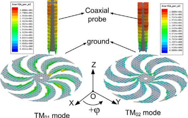
The proposed antenna introduces curved slots on the ground plane for obtaining ϕ-polarization, while the currents on the coaxial probe radiate θ-polarization. Both the currents on the ground plane
(a) (b)
Figure 1. Geometry and photograph of proposed antenna. (a) The structure of the proposed antenna with the parameters: R1 = 43 mm,R2= 38 mm, R3 = 38 mm,R4 = 6.5 mm,R5 = 4.4 mm,R6= 8 mm,
R7 = 17.7 mm,η = 15◦,H = 7 mm,εr= 2.65. (b) Photograph of the proposed antenna.
and the coaxial probe at the two resonant modes are shown in Fig. 2. With reference to the figure, the currents on the coaxial probe are in the direction of −Z, and the currents on the ground are mainly in the direction of−ϕ, at the TM01 mode. Therefore, the proposed antenna radiates the RHCP waves on the azimuth plane with the naturally guaranteed phase difference of 90◦ which is demonstrated in [7], when the two orthogonal polarizations have equal amplitude. Furthermore, the proposed antenna can also radiate LHCP when the curved slots bent in the anticlockwise. For the TM02 mode, the currents on the coaxial probe are still in the direction of−Z, but the currents on the ground are in the direction of +ϕ. Moreover, the currents in the direction of +ϕ increase rapidly, and the maximum radiation direction shifts downwards due to another half wave current on the ground plane, which can be clearly observed in Fig. 2. In addition, the maximum radiation direction shifts upwards when the curved slots are loaded on the patch.
3. EXPERIMENTAL RESULTS AND DISCUSSION
The effects of the curved slots width (η) and the unit number of the curved slots on the frequency ratio of TM01and TM02modes are studied. Fig. 3(a) shows|S11|of the proposed antenna with different unit numbers. With the increase of the unit number of curved slots, the lower band (TM01 mode) changes little while upper band (TM02 mode) shifts upward obviously. Adjusting the curved slots width (η), the frequency ratio can also be changed. In order to get a better impedance matching of both resonant modes, other parameters R4,R5 and R7 are also adjusted. As shown in Fig. 3(b), with the increase of
η, the lower band (TM01 mode) decreases while the upper band (TM02mode) shifts upward. It should be mentioned that the antennas in Fig. 3 radiate omnidirectional RHCP and ϕ-polarization at TM01 and TM02 modes, respectively. The ability of changing the frequency ratio easily makes the proposed
(a) (b)
Figure 3. Simulated|S11|for (a) different unit numbers of the slots and (b) the curved slot width η.
(a) (b)
(a) (b)
Figure 5. Measured radiation patterns of the proposed antenna. (a) 2.5 GHz. (b) 3.5 GHz.
antenna design more convenient.
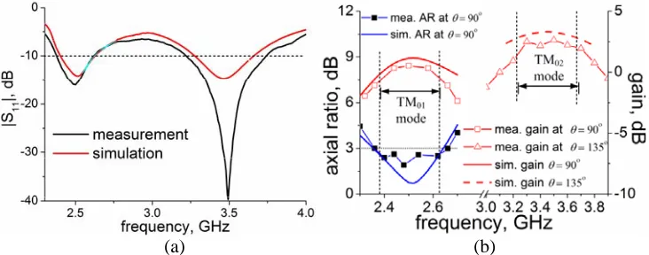
To verify the design, the proposed antenna with the parameters shown in Fig. 1(a) was fabricated and measured. A photograph of the proposed antenna is shown in Fig. 1(b). Fig. 4(a) shows the simulated and measured |S11|of the prototype antenna. The measured results show that the proposed antenna operates at 2.5 GHz and 3.5 GHz with 10-dB impedance bandwidths of 9.6% (2.38–2.62 GHz) and 14.9% (3.22–3.74 GHz), respectively, which are a little higher than the simulated results of 9.1% (2.4–2.63 GHz) and 12% (3.27–3.66 GHz) because of the inaccuracies in the fabrication process. Fig. 4(b) shows that the measured 3-dB AR bandwidth is about 12% (2.36–2.66 GHz) which agrees well with the simulated result of 11.3% (2.36–2.64 GHz). It should be noted that the measured 3-dB AR bandwidth can completely cover the 10-dB impedance bandwidth at the TM01 mode, indicating that the entire impedance bandwidths are usable. Fig. 4(b) also shows that the measured gains at both the TM01 and TM02 resonant bands of the prototype are about 0.3 and 2.5 dB in average, respectively, which are a little lower than the simulated results for the greater loss in the measurement. Both the ARs and the gains were also simulated and measured at other values ofϕwithθ= 90◦ at TM01 mode and θ= 135◦ at TM02mode, respectively, and similar results were obtained, showing that it is a good omnidirectional antenna. The measured radiation patterns at both the TM01 and TM02 modes are shown in Fig. 5. At TM01 mode, an omnidirectional RHCP monopole radiation pattern is obtained with the peak gains about 0.5 dB, as shown in Fig. 5(a). At TM02mode, an omnidirectionalϕ-polarized monopole radiation pattern is obtained with the peak gain about 2.5 dB at θ = 135◦ for the major radiator of ground, as shown in Fig. 5(b). All these radiation characteristics reveal that the proposed antenna is competent for the WLAN/WiMAX applications.
4. CONCLUSION
A dual-band dual-polarized circular microstrip patch antenna with 10 units of curved slots embedded on the ground plane is designed and fabricated. The frequency ratio of the two resonant bands can be easily changed by adjusting the width of the curved slots (η) and the unit number of the curved slots. The measured results show that the antenna operates at TM01and TM02modes with the bandwidths of 9.6% and 14.9% and radiates the RHCP andϕ-polarized patterns, respectively. The proposed antenna overcomes the disadvantages of the conventional printed monopoles with only unidirectional CP or θ -polarized radiation pattern. Therefore, with the lower profile of 0.056λ0 the proposed antenna will be a better candidate in the modern wireless communication systems such as WLAN and WiMAX.
ACKNOWLEDGMENT
REFERENCES
1. Wu, T., X.-W. Shi, P. Li, and H. Bai, “Tri-band microstrip-fed monopole antenna with dual-polarisation characteristics for WLAN and WiMAX applications,”Electron. Lett., Vol. 49, No. 25, 1597–1598, 2013.
2. Chen, C. and E. K. N. Yung, “Dual-band dual-sense chircularly-polarized CPW-fed slot antenna with two sprial slots loaded,” IEEE Trans. Antennas Propag., Vol. 57, No. 6, 1829–1833, 2009. 3. Verma, S. and P. Kumar, “Compact triple-band antenna for WiMAX and WLAN applications,”
Electron. Lett., Vol. 50, No. 7, 484–486, 2014.
4. Liu, P., Y. Zou, B. Xie, X. Liu, and B. Sun, “Compact CPW-fed tri-band printed antenna with meandering split-ring slot for WLAN/MiMAX applications,” IEEE Antennas Wireless Propagat.
Lett., Vol. 11, 1242–1244, 2012.
5. Basaran, S. C., U. Olgun, and K. Sertel, “Multiand monopole antenna with complementary split-ring resonators for WLAN and WiMAX applications,” Electron. Lett., Vol. 49, No. 10, 636–638, 2013.
6. Chizhik, D., J. Ling, and R. A. Vlenzuela, “The effect of electric field polarization on indoor propagation,” International Conference on Universal Personal Communications, 459–462, 1998. 7. Yu, Y., X. Shen, and S. He, “Compact omnidirectional antenna of circular polarization,” IEEE

![Ring transformation of 1,3,4 oxadiazoles into novel [1,2,4]triazolo[3,4 b][1,3,4]thiadiazines and their antimicrobial and antioxidant properties](data:image/gif;base64,R0lGODlhAQABAIAAAP///wAAACH5BAEAAAAALAAAAAABAAEAAAICRAEAOw==)