Polarization Matched Radiating Array for Electronically Steered
Phased Array Antenna
Raj Kumar1, Pramendra K. Verma1, *, Rajesh Roy1, and Machavaram V. Kartikeyan2
Abstract—A polarization matched 2×2 radiating array for electronically steered phased array antenna is presented. The antenna array is a multi-layer structure consisting of four square microstrip patch elements grown on each substrate to provide wide band operation at S-band. Dual polarizations of radiated wave from the antenna array have been achieved by feeding the array in series fed mode through horizontal and vertical ports. Designed 2×2 S-band dual polarized series fed antenna has been optimized on a finite element based ANSYS HFSS full wave solver. Controlling the amplitude of RF signal at input ports, the polarization can be matched to the target antenna polarization, hence antenna can work as polarization matched antenna. Gain of the developed antenna is 13 dBi, and the return loss is better than 10 dB over the frequency range of 2.3 to 2.5 GHz. This antenna can be used as radiating array for electronically steered phased array for S-band SOTM (SATCOM On The Move) application where the polarization of the antenna changes with movement of host platform.
1. INTRODUCTION
Polarization matched antennas are needed in applications where the polarization of antenna changes due to movement of host platform on which the antennas are placed. In the case of SOTM for airborne application, the polarization of antenna changes significantly (due to large yaw, roll and pitch of the airborne platform). The changes in polarization occur very fast due to fast movement of airborne platform, and hence the compensation for this should be applied in the design. These types of antennas are also required in both radar and communication systems which need polarization diversity. Demand of large bandwidth related services in wireless communication and network system has forced to improve the link performance and channel capacity of the communication system. This can be achieved by using various diversity techniques. Two diversity techniques, i.e., space and polarization diversity, are employed using antennas. In space diversity, multiple antennas are strategically spaced for transmission and reception. The polarization diversity is achieved using two orthogonal ports of the same antenna. With demand for miniaturization of communication systems and devices, the polarization diversity has become an attractive solution as it requires less space than space diversity [1].
Generally, mechanically steered antennas are used for airborne applications where the polarization of the antenna is matched with that of the target antenna by rotating the antenna or feed (in the case of reflector antenna) fast enough so that the polarization may be matched dynamically. The second option to compensate the polarization misalignment is to use circularly polarized (CP) antenna which would provide polarization matching over the plane of CP. The circularly polarized antenna would have the polarization loss depending on the angle of transmitted/ received signal and axial ratio variations over the frequency band. Both of the above types have the limitations in terms of requirement of additional sub-system and losses due to circular polarization. To compensate the polarization loss completely, it is proposed to use dual polarized antenna with two inputs polarizations whose resultant
Received 26 September 2018, Accepted 21 October 2018, Scheduled 30 October 2018 * Corresponding author: Pramendra K. Verma ([email protected]).
output polarization can be aligned to target antenna polarization by changing the excitation amplitude of the antenna inputs.
Feeding the microstrip patch antenna at two orthogonal edges, through edge feed or probe feed and hence exciting transverse magnetic TM01 and TM10 modes with orthogonal polarization, dual-polarized antennas can be realized [2, 3]. As the impedance bandwidth of the antenna depends mainly on the feeding techniques, a maximum of 1.9% impedance bandwidth can be achieved using probe-fed microstrip arrays [4] and up to 15% with stacked structure [5–7].
In a coplanar geometry 20% bandwidth can be achieved for horizontal polarization, and in this case the vertical polarization is achieved by microstrip line through an H-shaped slot [8]. Microstrip antennas bandwidth can be increased up to 22% with proximity coupling [9, 10].
In dual polarized microstrip patch antenna arrays using coplanar microstrip feeding network, we can achieve an impedance bandwidth up to 2% if a corporate feeding network is employed [11]. Standard coplanar series feeding has impedance bandwidth of 1.1% [12] and 2.9% with line or patch tapering [13, 14] for single polarization.
Polarization diversity in MIMO (Multi-Input Multi-Output) system provides improved multiplexing gains, mainly in Rayleigh fading channels and in the presence of high transmitting fading signal correlation [15]. Radar uses dual polarized antennas for getting information in horizontal and vertical planes simultaneously [16, 17]. Design and realization of various dual polarized antenna arrays to achieve high gain have been reported [18–25].
Present paper discusses a series fed 2×2 polarization matched antenna array. In this, the amplitude of the input ports can be varied to align the polarization of antenna with the target antenna polarization. Dual layer geometry has been used to obtain wide band of operation. A gain of approximately 13 dBi within the bandwidth and side lobe levels (SLLs) better than −10 dB were targeted. Design and realization of a series fed polarization matched antenna including simulated and measured results is presented in this paper.
The designed antenna can be used as radiating array for electronically steered phased array antenna to be used with fast moving airborne vehicle. Being electronically controlled, the designed antenna can match the polarization of antenna with the targeted antenna in a very fast manner as compared to conventional mechanically rotating antenna.
2. DESIGN CONSIDERATION
obtain the desired orientation of polarization. This can be demonstrated as follows.
Suppose thatax anday are the magnitude of two orthogonally polarized vectors, and the resultant amplitude and phase of the two vectors can be written as
A =
a2
x+a2y
θ = tan−1 ay ax
In the above equation ifay becomes zero the signals become X polarized or horizontally polarized. On the other hand, when ax becomes zero the resultant signal becomes Y polarized or vertically polarized. Further by making amplitudes of both ax and ay equal to unity the polarization would be diagonal.
A dual polarized 2×2 array antenna has been designed using series fed configuration at 2.4 GHz. It is designed in stacked layers with 10 mm air gap in between to increase the bandwidth of operation. Both the bottom and top layers of the antenna have been designed on Rogers 5880 RT Duroid substrate material having εr = 2.2 and tanδ= 0.0009. The thicknesses of top and bottom layers are 30 mil and 60 mil, respectively. Bottom layer consists of a series fed microstrip antenna with dual orthogonal ports. The sketch of designed antenna with all the dimensions is shown in Figure 1. To achieve 50 Ω impedance matching, each microstrip line is connected to a quarter wave transformer of length 22 mm and width 2.8 mm. The square microstrip patch at both of the layers has dimension of 41.25 mm×41.25 mm.
Figure 1. Detailed Sketch of the designed antenna.
Two orthogonal ports of the antenna are fed with different amplitudes by using a digital attenuator. It adjusts the input signal at both input ports as per the polarization tilt requirement.
3. SIMULATION & EXPERIMENTAL RESULTS
The designed antenna has been modeled, simulated and optimized on ANSYS HFSS software taking proper boundary conditions. 3D CAD model of the antenna is shown in Figure 2.
The designed antenna has been developed, and its S parameters have been measured by vector network analyzer. Photographs of the developed 2×2 series fed microstrip patch antenna are shown in Figure 3. A metallic enclosure is also fabricated for holding the two PCBs with an optimum air gap.
Figure 2. 3D CAD model of designed antenna.
(b)
(a) (c)
Figure 3. Fabricated antenna. (a) Bottom layer (b) Top layer. (c) Complete assembly.
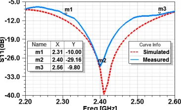
Figure 4. Reflection coefficient of H-port. Figure 5. Reflection coefficient of V-port.
(b) (a)
The reflection coefficients (S11&S22) of the antenna at port 1 & port 2 are better than 10 dB over the frequency band of 2.31 to 2.56 and 2.32 to 2.51 GHz, respectively. Hence 8% impedance bandwidth is achieved. The simulated radiation patterns of the antenna at V and H ports are quite similar. Simulated and measured radiation patterns of the antenna at 2.4 GHz are shown in Figure 6.
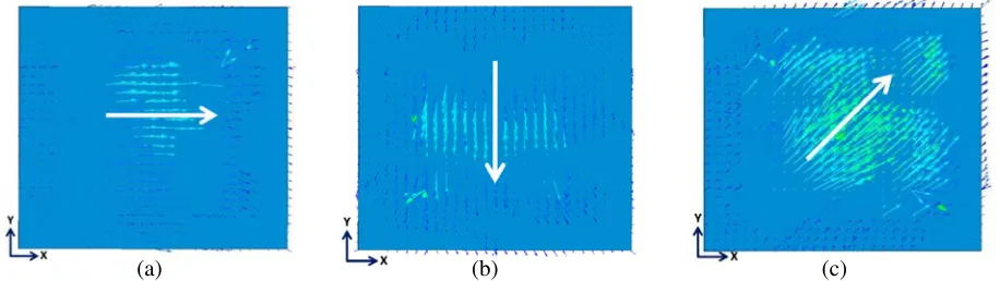
The electric field vector of the antenna which decides the polarization is shown in Figure 7 for different combinations of excitation amplitudes at both input ports using digital attenuator.
(b)
(a) (c)
Figure 7. Electric field orientation of antenna with different input amplitude (a) ax = 1, ay = 0, (b)ax= 0, ay= 1, (c) ax = 1,ay = 1.
The antenna was also evaluated by exciting both of the ports simultaneously with equal power, and in this case diagonal polarization was achieved. The gain of the antenna is measured using SGH method, which is 13 dBi at 2.4 GHz for both V- and H-ports.
4. CONCLUSION
A low profile, light weight 2×2 series fed microstrip antenna has been designed, simulated, optimized and developed at S-band frequency. Measured results are very close to the simulated values. Dynamical control of polarization has been achieved by changing the amplitude of RF signals at the horizontal and vertical ports of antenna using digital attenuator. The antenna is a most suitable radiating element of electronically steered phased array antenna for SATCOM on the move application.
ACKNOWLEDGMENT
The authors are thankful to Director, Defence Electronics Applications Laboratory, Dehradun (Uttrakhand), India for granting permission to publish this paper.
REFERENCES
1. Mishra, P. K., D. R. Jahagirdar, and G. Kumar, “Broadband dual polarized space fed antenna arrays with high isolation,” Progress In Electromagnetics Research C, Vol. 55, 105–113, 2014. 2. Di Bari, R., T. Brown, S. Gao, M. Notter, D. Hall, and C. Underwood, “Dual polarized printed
S-band radar array antenna for spacecraft applications,”IEEE Antennas and Wireless Propagation Letters, 2011.
3. Du Toit, L. J. and J. H. Cloete, “Dual polarized linear microstrip patch array,” Proc. IEEE Antennas and Prop. Symp. Dig., 810–813, 1987,
4. Granholm, J., K. Woelders, M. Dich, and E. L. Christensen, “Microstrip antenna for polarimetric C-band SAR,”1994 Antennas & Propagation Society Int. Symposium, Vol. 3, 1844–1847, Seattle, USA, 1994.
6. Granholm, J. and K. Woelders, “Dual polarization stacked microstrip patch antenna array with very low cross-polarization,” IEEE Trans. on Antennas and Propagation, Vol. 49, No. 10, 1393–1402, Oct. 2001.
7. Granholm, J. and N. Skou, “Dual-polarization, wideband microstrip antenna array for airborne C-band SAR,” Proc. International Conf. on Phased Array Systems and Technology, Dana Point, CA, 243–246, 2000.
8. Wang, W., S.-S. Zhong, and X.-L. Liang, “A dual-polarized stacked microstrip antenna subarray for X-band SAR application,” Conf. Rec. 2004 IEEE Antennas and Propagation. Society Int. Symposium, Vol. 2, 1603-160, Jun. 2004.
9. Neves, E. S., W. Elmarissi, and A. Dreher, “Design of a broad-band low cross-polarized X-band antenna array for SAR applications,” IEEE 2004 AP-S Symposium, Vol. 3, 2460–2463, 2004. 10. Gao, S. and A. Sambell, “Dual-polarized broad-band microstrip antennas fed by proximity
coupling,”IEEE Trans. Antenna and Propagation, Vol. 53, 526–530, Jan. 2005.
11. Gao, S. and S. S. Zhong, “A dual-polarized microstrip antenna array with high isolation fed by coplanar network,” IEEE 1998 Radio and Wireless Conf., 213–216, Colorado Springs, CO, USA, 1998.
12. Sainati, R. A.,CAD of Microstrip Antennas for Wireless Applications, Artech House, Boston, MA, 1996.
13. Chen, Z. and S. Otto, “A taper optimization for pattern synthesis of microstrip series-fed patch array antennas,”Conf. Rec. 1009 Wireless Technology Conf., 160–163, 2009.
14. Tao, Y., Y. Ning, and L.-W. Li, “Novel series-fed taper antenna array design,” Antenna and Wireless Propagation letters, IEEE, Vol. 7, No. 4, 362–365, Jul. 2008.
15. Oestges, C., B. Clerckx, M. Guillaud, and M. Debbah, “Dual-polarized wireless communications: From propagation models to system performance evaluation,”IEEE Trans. Wireless Comm., Vol. 7, No. 10, 4019–4031, 2008.
16. Giulli, D., “Polarization diversity in radars,”Proc. of the IEEE, Vol. 74, No. 2, 245–269, 1986. 17. Wang, Y. and V. Chandrasekar, “Polarization isolation requirements for linear dual-polarization
weather radar in simultaneous transmission mode of operation,” IEEE Trans. Geoscience and Remote Sensing, Vol. 44, No. 8, 2019–2028, 2006.
18. Zhong, S.-S., X.-X. Yang, S.-C. Gao, and J.-H. Cui, “Corner-fed microstrip antenna element and arrays for dual-polarization operation,”IEEE Trans. Antennas Propag., Vol. 50, No. 10, 1473–1480, 2002.
19. Gao, S. and A. Sambell, “Low-cost dual polarized printed array with broad bandwidth,” IEEE Trans. Antennas Propag., Vol. 52, No. 12, 3394–3397, 2004.
20. Lau, K. L. and K.-M. Luk, “A wideband dual-polarized L-probe stacked patch antenna array,”
IEEE Antennas Wireless Propagat. Lett., Vol. 6, 529–532, 2007.
21. Acimovic, I., D. A. McNamara, and A. Petosa, “Dual-polarized microstrip patch planar array antennas with improved port-to-port isolation,” IEEE Trans. Antennas Propag., Vol. 56, No. 11, 3433–3439, 2008.
22. Mishra, P. K., D. R. Jahagirdar, and G. Kumar, “An array of broadband dual polarized electromagnetically coupled microstrip antennas,” Progress In Electromagnetics Research C, Vol. 44, 211–223, 2013.
23. Chakrabarti, S., “Development of shared aperture dual polarized microstrip antenna at L-band,”
IEEE Trans. Antennas Propag., Vol. 59, No. 1, 294–297, 2011.
24. Jiang, X., Z. Zhang, Y. Li, and Z. Feng, “A planar wide band dual-polarized array for active antenna system,”IEEE Antennas Wireless Propagat. Lett., Vol. 13, 544–547, 2014.