Modeling of the Electromagnetic Field of a Rectangular Waveguide
with Side Holes
Islam J. Islamov*, Elshad G. Ismibayli, Yusif G. Gaziyev, Simnara R. Ahmadova, and Rashid Sh. Abdullayev
Abstract—In this work, we simulate the electromagnetic field of a rectangular waveguide with side holes. The Helmholtz equations for a given waveguide and dispersion equations are solved. As a result of numerical calculations, the obtained numerical values build the dependence of the modulus of the effective impedance on the wavelength for different types of waves.
1. INTRODUCTION
The intensive development of microwave technology has led to the emergence of a variety of electrodynamic tasks. One of these tasks is the study of filters with wave leakage, designed for high power levels. From a technical viewpoint, such filters represent the main waveguide connected to the side waveguides through a system of round or elliptical holes. As a connection in such devices, a system of slits of various shapes and sizes can be used. Despite the diversity of communication elements, their frequency is common to all. As known, from a mathematical point of view, the calculation of electromagnetic fields in such structures is reduced to solving a boundary value problem. In this case, the satisfaction of the boundary conditions of the components of the electric and magnetic fields on the coupling elements is extremely difficult. The representation of boundary conditions of components of the electric and magnetic fields on the coupling elements on openings of a rectangular waveguide and the boundary conditions of an impedance type outside the openings in the form of a linear combination of electric and magnetic fields allow us to construct a system of integral equations for the problem of radiation from a finite waveguide antenna array with an impedance flange. One approach to solving such problems is to use approximate boundary conditions [1–6]. IfEτ andHτ are tangential components of an electromagnetic field on a certain interface between two regions, the concept of surface impedance
Zs is introduced (in the general case, complex and anisotropic), connecting these components by the relation
Eτ =ZsHτ. (1)
A review of a large number of tasks, whose effective solution is made possible by the introduction of impedance boundary conditions, is given in [7–11].
2. FORMULATION OF THE PROBLEM
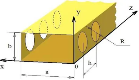
Let us consider a rectangular waveguide, in which a row of holes of a circular shape is located on a narrow wall along a line parallel to the z axis, as shown in Fig. 1.
In a rectangular coordinate system whose origin coincides with one of the vertices of the rectangle, we introduce the following notation: α — the size of the wide wall of the main waveguide,b — the size
Received 11 January 2018, Accepted 2 February 2019, Scheduled 18 February 2019
* Corresponding author: Islam Jamal Islamov ([email protected]).
Figure 1. A rectangular waveguide with holes in narrow walls.
of the narrow wall of the main waveguide, R — the hole radius, h — the distance between the centers of the holes.
Let us consider the propagation of magnetic waves in the current waveguide, provided that the surface impedance of a narrow wall is known, and it can be calculated from the relationships given in [12–17].
3. SOLUTION
The electromagnetic field in such a waveguide is determined through a longitudinal component that is satisfied by the Helmholtz equation.
∂2H˙z
∂x2 +
∂2H˙z
∂y2 +
∂2H˙z
∂z2 +k 2 ˙
Hz= 0, (2)
wherek= 2λπ is the wave number.
Inhomogeneous impedance boundary conditions on a narrow wall atx=α
˙
Ey =−Zs(y, z) ˙Hz. (3) The remaining walls are ideally conductive.
Periodic surface impedance can be represented as a double Fourier series.
Zs(y, z) =
∞
p=0
∞
r=0
Aprcospπ
b y·cos rπ
h z+Cprcos pπ
h y·sin rπ
h z
, (4)
where coefficients Apr and Cpr are calculated from the relations given in [17, 18].
Since the surface impedance is a periodic function of the coordinatez,the solution of Equation (3) will be sought in the form of a Fourier series.
˙
Hz =
∞
n=0
∞
s=0
A(ns)) cosγxn(s)xcosnπ
b ye
−jβsz, (5)
whereβS=β0+p2nπ, γxn(s)2=k2−βs2−(nπb )2, β0 — complex constant propagation to be determined.
Based on Maxwell’s equations for magnetic waves, one can obtain the following expression relating the electric ˙Ey and magnetic ˙Hz components
˙
Ey =−jωμ0·
1
γ⊥(sn)2 ∂H˙z
∂x , (6)
Given the relations in Eqs. (5) and (6), for ˙Ey components, we get
˙
Ey =−jωμ0
∞ n=0 ∞ s=0
γxn(s)
γ⊥(sn)2A
(s)
n sinγxn(s)xcosnπb ye−jβsz. (7)
Using the boundary condition in Eq. (3) and expression (7) by simple transformations, we obtain the following relation
∞
n=0
∞
s=−∞
Vn(s)A(ns)cospπ
b ye
−jβzz =
∞ p=0 ∞ r=0 ¯
Aprcospπb y·cosrπnz+ ¯Cprcospπb y·sinrπnz
×∞ p=0
∞
r=o
Yxn(s)
Y⊥(sn)2U
(s)
n A(ns)cosnπb ye−jβzz, (8)
where coefficients Vn(s) and Un(s) are determined by the expressions
Un(s)= cosγxn(s)d, Vn(s)= jkγ
(s)
xn
γ⊥(sn)
sinγxn(s)d. (9)
Coefficients Apr and Cpr are normalized to the wave resistance of the free space Z characteristic
impedance of free space z0 =
μ0
ε0. Replacing the trigonometric functions cos rπ
nz, sinrπnz with exponential functions, we obtain
∞
n=0
∞
r=−∞
Vn(s)A(ns)cospπ
b ye
−jβyz = 1
2 ∞ p=0 ∞ r=0
z+pre−jrπnz+zpr−e−jrπnz cosnπ b y ×∞ n=0 ∞
r=−∞
γxn(s)
γ⊥(sn)2U
(s)
n A(ns)cosnπb ye−jβsz, (10)
wherezpr+ = ˜Apr+jC˜pr, zpr− = ˜Apr−jC˜pr.
Given the orthogonality of the transverse eigen functions of the waveguide and the exponential functions e−jβxz on the period of the structure, we obtain a system of homogeneous linear algebraic
equations for the wave amplitudesA(ks).
∞
k=0
˜
z+p0+ ˜zp−0
Uk(s)−(1 +δnk)δnk· Vk(s)
A(ks)+1 2
∞
(˜zpr+Uk(s−r)A(ks−r)+ ˜z−prUk(s+r)Ak(s+r)) = 0, (11)
wheren= 0,1,2, . . .; s= 0,±1,±2, . . .; p=|n−k|; δnk — Kronecker symbol.
System in Eq. (11) has a nontrivial solution if its determinant is formed from coefficients at A(ks)
equal to zero. Opening the determinant of system in Eq. (11), we obtain a dispersion equation in the matrix form, from which the propagation constants β0 are determined.
4. NUMERICAL RESULTS
The considered rectangular waveguide with impedance narrow walls is an electrodynamic model of an absorbing harmonic filter. In it, the filter cell is the connection of a secondary circular waveguide with a main rectangular waveguide. The cross section of the main waveguide a×b= 48×24 mm; the radii of the auxiliary waveguides are equal to R = 9 mm; the distance between adjacent cells is equal to
h = 19 mm. The analysis of the dispersion Equation (11) shows that with selected parameters, the influence of higher spatial harmonics on the values of the propagation constants is insignificant. The main contribution is made by central elements of the determinant of the system in Eq. (11), standing on the main diagonal
˜
whereγ⊥2 =γx2+ (nπb )2, n= 0,1,2, . . ..
Dispersion Equation (12) describes the volume (fast) waves in the guide structure. For surface waves propagating in the impedance waveguide, in Eq. (12) it is necessary to make a replacement
γx →jγx, then we get
˜
z00γ⊥2chγxa−jkγxshγxa= 0, (13)
whereγ⊥2 =−γx2+ (nπb )2.
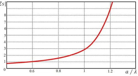
Dispersion Equations (12), (13) allow us to obtain a spectrum of both bulk and surface waves propagating in such a structure. As a result of the analysis, the frequency characteristics of the constant propagation of bulk and surface waves were obtained depending on various values of surface impedance and wavelengths. The results of numerical calculations are presented in Figs. 2, 3, 4.
Figure 2. Dependence of the modulus of the effective impedance|Zseff|on wavelengtha/λand surface waves in the case of one.
Figure 3. Dependence of the normalized impedance wall: 1 — surface wave; 2 — first volume (quasi H10) wave; 3 — second volume
(quasi H20) wave; 4 — third volume (quasi H30)
wave propagation constant for bulk.
Figure 4. Dependence ˜β(|Zseff|) with a/λ= 0.8 in the case of two impedance walls bulk: 1 — quasi
H10 wave; 2 — first surface wave; 3 — second
surface wave.
Fig. 2 gives the dependence of modulus of the imaginary part of the effective impedance on the length for the holes with the radius indicated above. Calculations show that the reactive part of the effective impedance has a capacitive characteristic. The calculations are performed for the effective value of the surface impedance, obtained on the basis of the formulas of the article [5]:
Zseff =
1
b·h ·
b
0
h
0
Zs(y, z)·Zs∗(y, z)dydz, (14)
Figure 3 shows the frequency dependences of the constant propagation of bulk waves (quasi H10,
quasiH20, quasiH30) normalized to the wave number, and the surface wave, which is absent in a regular
waveguide.
As can be seen from Fig. 3, the capacitive nature of the surface impedance of one wall of the waveguide shifts λkr towards larger values of the wavelength. In addition, with decreasing wavelength, higher types of waves are excited. Calculations show that with increasing |Zseff|, the propagation constant increases.
Numerical analysis is also carried out for a waveguide with two impedance walls. In such a structure, as shown by calculations, the propagation of two surface waves is possible. In Fig. 4, such a case is considered fora/λ= 0.8 and at different surface impedance values.
WhenZseff →0, the waves quasiH10transforms into wave H10of a regular waveguide, and surface
waves degenerate. It is also seen from the figure that for some values of Zseff, the volume wave (curve 1) undergoes cutoff. With increasing Zseff values, the propagation constants β decrease, with one of the surface waves (curve 3) ˜β tending to unity. The wave remains surface, and the other wave (curve 2) goes from surface to volume.
5. CONCLUSION
A dispersion equation in matrix form is obtained for a waveguide with an infinite number of holes along a narrow wall. For such a structure, the values of the effective surface impedance are calculated, and the dispersion characteristics are obtained depending on its magnitude and wavelength. The methods of investigation of the dispersion properties of the waveguiding system made it possible to determine its frequency properties at various degrees of coupling of the waveguides. The results obtained are in good agreement with the general physical concepts of the theory of coupled modes and indicate the difference in the behavior of the dispersion dependences of coupled identical and not identical waveguides.
It is shown that in such a structure it is possible to propagate both bulk and surface waves. It has been established that in a waveguide with two impedance walls, the existence of two surface waves is possible which, under certain parameters of the structure, degenerate.
It is revealed that the surface impedance significantly affects the matching characteristics and interconnection of elements of the final waveguide antenna array.
The results of this work can be used in the development of waveguide antennas and antenna arrays, and materials may be useful in the development of various functional elements of the microwave range.
REFERENCES
1. Chen, S. C. and W. C. Chew, “Electromagnetic theory with discrete exterior calculus,” Progress In Electromagnetics Research, Vol. 159, 59–78, 2017.
2. Jia, M. M., S. Sun, Y. Li, Z.-G. Qian, and W. C. Chew, “Acceleration of perturbation-based electric field integral equations using fast fourier transform,”IEEE Transactions on Antennas and Propagation, Vol. 64, No. 10, 4559–4564, 2016.
3. Chew, W. C., M. S. Tong, and B. Hu, “Integral equation methods for electromagnetic and elastic waves,” San Rafael, CA, USA: Morgan & Claypool, 2008.
4. Na, D.-Y., H. Moon, Y. A. Omelchenko, and F. L. Teixeira, “Local, explicit, and charge-conserving electromagnetic particle-in-cell algorithm on unstructured grids,” IEEE Transactions on Plasma Science, Vol. 44, No. 8, 1353–1362, 2016.
5. Chen, S. and W. C. Chew, “Discrete electromagnetic theory with exterior calculus,”2016 Progress in Electromagnetic Research Symposium (PIERS), 896–897, Shanghai, China, August 8–11, 2016. 6. Kim, H.-M., H. Jang, P. Pramudita, M.-K. Kim, and Y.-H. Lee, “Monolithic integration of self-aligned nanoisland laser with shifted-air-hole waveguide,”Optics Express, Vol. 26, No. 10, 12569– 12578, 2018.
8. Zemlyakov, V., S. Krutiev, and M. Tyaglov, “Complex geometry apertures for resonant diaphragms in rectangular waveguides,” Journal of Electromagnetic Waves and Applications, Vol. 32, No. 18, 2470–2480, 2018.
9. Koenen, C., G. F. Hamberger, U. Siart, T. F. Eibert, H. U. Nickel, G. D. Conway, and U. Stroth, “A low-reflectivity vacuum window for rectangular hollow waveguides,” IEEE Transactions on Microwave Theory and Techniques, Vol. 66, 128–135, 2018.
10. Bird, T. S., V. Lingasamy, K. T. Selvan, et al., “Improved finite-range gain formula for open-ended rectangular waveguides and pyramidal horns,”IET Microwaves Antennas& Propagation, Vol. 11, No. 14, 2054–2058, 2017.
11. Yeap, K. H., E. V. S. Wong, H. Nisar, et al., “Attenuation in circular and rectangular waveguides,”
Electromagnetics, Vol. 37, No. 3, 171–184, 2017.
12. Scott, M. M., D. L. Faircloth, J. A. Bean, et al., “Permittivity and permeability determination for high index specimens using partially filled shorted rectangular waveguides,”Microwave and Optical Technology Letters, Vol. 58, No. 6, 1298–1301, 2016.
13. He, B., C. Lu, N. N. Chen, D. S. Lin, M. Rosu, and P. Zhou, “Time decomposition method for the general transient simulation of low-frequency electromagnetics,” Progress In Electromagnetics Research, Vol. 160, 1–8, 2017.
14. Chen, S. C. and W. C. Chew, “Electromagnetic theory with discrete exterior calculus,” Progress In Electromagnetics Research, Vol. 159, 59–78, 2017.
15. Islamov, I. J., E. G. Ismibayli, M. H. Hasanov, Y. G. Gaziyev, and R. S. Abdullayev, “Electrodynamics characteristics of the no resonant system of transverse slits located in the wide wall of a rectangular waveguide,” Progress In Electromagnetics Research Letters, Vol. 80, 23–29, 2018.
16. Kamada, S., T. Okamoto, S. E. El-Zohary, A. Mori, and M. Haraguchi, “Design optimization and resonance modes of a plasmonic sensor based on a rectangular resonator,” Optics Communication, Vol. 427, 220–225, 2018.
17. Azeez, Y. F., R. J. Collier, N. M. Ridler, and P. R. Young, “Establishing a new form of primary impedance standard at millimeter-wave frequencies,” IEEE Transactions on Instrumentation and Measurement, Vol. 68, No. 1, 294–296, 2019.