Fuzzy Controller For Reactive Power Compensation With Statcom To
Improve Power Factor
Bade Varsha L & R. M. Nagarale
Abstract: This paper deals with modelling of STATCOM along with the design of linear current and voltage controllers. The fuzzy logic control method is used to design linear current and voltage controllers to improve the power factor with the help of reactive power compensation. STATCOM is nothing but the static synchronous compensator which regulates the voltage and corrects the power factor at the point of common coupling by injecting reactive power. The principle of operation is same as that of synchronous condenser. The use of proposed method removes the fluctuations and improves the magnitude of the current and voltage also phase angle which goes to nearly zero value. The performance of the method is obtained through MATLAB SIMULINK tool box.
Index Terms: Reactive Power Compensation, STATCOM, Fuzzy controller.
I. INTRODUCTION
The STATCOM i.e. static compensator is very commonly used for the reactive power control. The STATCOM is also known as static VAR generator (SVG) is a voltage converter device which uses in order to generate the active and reactive power needed by the
system. The STATCOM has several
advantages such as fast response, continuous and quick control of reactive power. The power system becomes very complex because there is interconnection of long distance transmission lines [1-3]. The grids become unstable in nature as the loads are vary in their phase angle and magnitude that affects on power factor [4-6]. Commissioning new transmission systems was extremely expensive and also takes more amount of time to set up. Therefore, in order to meet increasing power demands, utilities must rely on power export or import arrangements through the existing transmission systems. To
improve power factor the capacitor banks are used but it is having number of disadvantages [7].
To avoid these disadvantages the Power electronic devices are used in the field of power transmission and distribution systems. The reactive power (VAR) compensation and control have been recognized which is efficient and increases the power system transmission capability and stability [8-11]. The FACTS (Flexible AC Transmission Systems) devices, such as STATCOM has been introduced recently which employs a VSI with a fixed DC link capacitor as a static replacement of the synchronous condenser. It does not require no. of capacitor or inductor banks. Only a fixed set of capacitor provides the required VAR control, with a rapid control of bus voltage and improvement of utility power factor. It has
some advantages over conventional
thyristorised converters in terms of speed of response [12]. The penalty paid for this improvement is in terms of some harmonics which requires the separate filtration techniques. The SPWM i.e. Sinusoidal Pulse Width Modulation technique is used to reduce the harmonic distortion [13] the modulation index is also increases so that this modulation index minimises the size of link reactor. The modelling, analysis of STATCOM steady state and dynamic performance have been studied using non-linear controller [14]. The dynamic and steady state nature of STATCOM using SVPWM method (Space Vector Pulse Width Modulation) is more better than SPWM because SVPWM inverter has higher modulation index [15].
along with the parameter of the coupling inductor and storage capacitor.
These controllers are used in STATCOM and control the reactive power for improvement of power factor on the variation of DC link voltage. But in this paper some fluctuations are there so that in order to avoid these fluctuations and to improves the reactive power we are introduced fuzzy controller for the improvement of power factor with reactive power compensation. In addition, this research work demonstrates fast, dynamic performance of the STATCOM in various operating conditions.
This paper is organized as follows. Section II illustrates the modelling of the STATCOM & analysis. Section III presents the design of fuzzy controller for the STATCOM. Section IV presents the simulation results. Finally, Section V concludes this paper.
II. STATCOM MODELLING AND ANALYSIS
A. Operating principle:
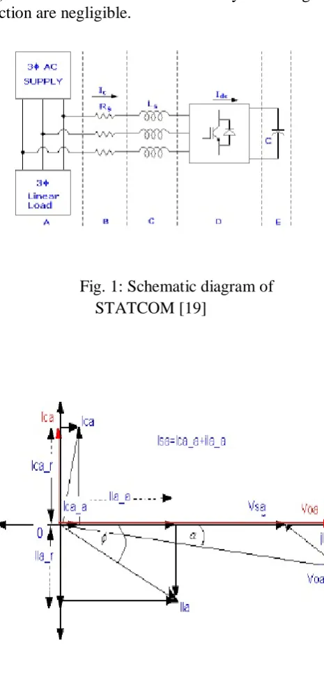
As is well known, the STATCOM is, in principle, a static replacement of the age-old synchronous condenser. Fig.1 shows the schematic diagram of the STATCOM at PCC through coupling inductors. The fundamental phasor diagram of the STATCOM terminal voltage with the voltage at PCC for an inductive load in operation, neglecting the harmonic content in the STATCOM terminal voltage, is shown in Fig.2. Ideally, increasing the amplitude of the STATCOM terminal voltage V~oa above the amplitude of the utility voltage V~sa causes leading current I~ca to be injected into the system at PCC as shown in Fig.2.
B. Modeling:
The modelling of the STATCOM, through well known, is viewed in the lines below, for the sake of convenience. The modelling is carried out with the following assumptions:
1) All switches are ideal.
2) The source voltages are balanced.
3) Rs represents the converter losses of the coupling inductor.
4) The harmonic contents caused by switching action are negligible.
Fig. 1: Schematic diagram of STATCOM [19]
Fig. 2: Phasor diagram for inductive load operation [19]
and leading β axis and both converted into dq two-phase rotating co-ordinates. The Park’s abc to dq transformation matrix is used here. The actual proposed circuit is too complex to analyze as a whole, so that it is partitioned into several basic sub-circuits, as shown in Fig.1.
The 3-phase system voltage Vs,abc lagging with the phase angle α to the STATCOM output voltage Vo,abc and differential form of the STATCOM currents are defined in (1) and (2).
𝑣𝑠,𝑎𝑏𝑐 = [
𝑣𝑠𝑎 𝑣𝑠𝑏
𝑣𝑠𝑐 ] = √2
3𝑣𝑠
[
sin(𝜔𝑡 − 𝛼)
sin (𝜔𝑡 − 𝛼 −2𝜋
3)
sin (𝜔𝑡 − 𝛼 +2𝜋
3)]
(1)
𝐿𝑠 𝑑
𝑑𝑡(𝑖𝑐,𝑎𝑏𝑐) =-𝑅𝑠𝑖𝑐,𝑎𝑏𝑐+ 𝑣𝑠,𝑎𝑏𝑐 - 𝑣𝑜,𝑎𝑏𝑐 (2)
Where, 𝑣𝑠,𝜔̅, 𝑅𝑠 and 𝐿𝑠 have their usual connotations. The above voltages and currents are transformed into dq frame.
𝐿𝑠 𝑑
𝑑𝑡(𝑖𝑐𝑞) = -𝑅𝑠𝑖𝑐𝑞- 𝜔𝐿𝑠𝑖𝑐𝑑 + 𝑣𝑠𝑞 - 𝑣𝑜𝑞 (3)
𝐿𝑠 𝑑
𝑑𝑡(𝑖𝑐𝑑) = 𝜔 𝐿𝑠𝑖𝑐𝑞 - 𝑅𝑠𝑖𝑐𝑑 + 𝑣𝑠𝑑 - 𝑣𝑜𝑑 (4)
The switching function S of the STATCOM can be defined as follows:
S = [ 𝑆𝑎
𝑆𝑏 𝑆𝑐
] = √2
3 m
[
sin( 𝜔𝑡)
sin (𝜔𝑡 −2𝜋
3)
sin (𝜔𝑡 +2𝜋
3)]
(5)
The modulation index, being constant for a programmed PWM, is given by,
MI = 𝑣𝑜,𝑝𝑒𝑎𝑘
𝑉𝑑𝑐 = √ 2
3 m (6)
The STATCOM output voltages in dq transformation are
𝑣𝑜,𝑞𝑑𝑜 = m [0 1 0]𝑇𝑣𝑑𝑐 (7)
The dc side current in the capacitor in dq transformation
𝑖𝑑𝑐 = m [0 1 0][𝑖𝑐𝑞 𝑖𝑐𝑑 𝑖𝑐𝑜]𝑇 (8)
The voltage and current related in the dc side is given by,
𝑑𝑣𝑑𝑐 𝑑𝑡 =
𝑚
𝐶 𝑖𝑐𝑑 (9)
𝑑 𝑑𝑡[
𝑖𝑐𝑞 𝑖𝑐𝑑 𝑣𝑑𝑐
] =
[
−𝑅𝑠
𝐿𝑠 −𝜔 0
𝜔 −𝑅𝑠
𝐿𝑠 − 𝑚 𝐿𝑠
0 𝑚
𝐶 0 ]
[ 𝑖𝑐𝑞 𝑖𝑐𝑑 𝑣𝑑𝑐
] + 𝑉𝑠
𝐿𝑠 [
−sin 𝛼 cos 𝛼
0
] (10)
III. DESIGN OF FUZZY CONTROLLER FOR STATCOM
A. Basics of Fuzzy controller
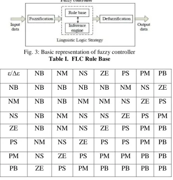
The determination of the output control signal, is done with an inference engine with a rule base having if-then rules in the form of ”IF ε is...AND ∆ε is...,THEN output is...” With the rule base, the value of the output is changed according to the value of the error signal ε, and the rate-of-error ∆ε. The structure
and determination of the rule is are using trial-and-error methods and is also done through experimentation. All the variable fuzzy subsets for the inputs ε and ∆ε are defined as (NB, NM, NS, Z, PS, PM, PB). The fuzzy control rules is illustrated in table I. The basic diagram of fuzzy controller is shown in Fig.3.
Fig. 3: Basic representation of fuzzy controller Table I. FLC Rule Base
ε/∆ε
NB
NM
NS
ZE
PS
PM
PB
NB
NB
NB
NB
NB
NM
NS
ZE
NM
NB
NB
NM
NM
NS
ZE
PS
NS
NB
NM
NS
NS
ZE
PS
PM
ZE
NB
NM
NS
ZE
PS
PM
PB
PS
NM
NS
ZE
PS
PS
PM
PB
PM
NS
ZE
PS
PM
PM
PB
PB
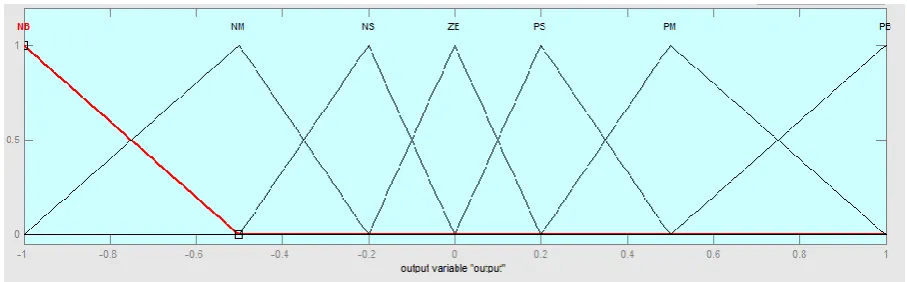
The membership functions for error, change in error and output is shown in Fig.4, 5 and 6 respectively.
Fig. 4: Membership function of error(ε)
Fig.5: Membership function of change in error(∆ε)
Fig.6: Membership function of output
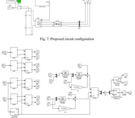
A. Simulation using FLC
In the simulation diagram is divided in to two parts for the convience i.e. Fig.7 and 8 shows proposed circuit configuration and proposed circuit control using FLC respectively. In proposed circuit configuration, the source is connected to load so that it produces impact on gate pulsating signal because controller output gives to Vsc and Vdc gets improved. When
Vdc improved, the reactive power injected to the system is improve and power factor improves. The control circuit using FLC is shown in detailed in Fig.8. In control circuit the Clark’s and Park’s transformation is performed to give signals to the discrete SVPWM (Space Vector Pulse Width Modulation) generator. With SVPWM pulses are generated.
Fig. 7: Proposed circuit configuration
B. Responses using FLC Model
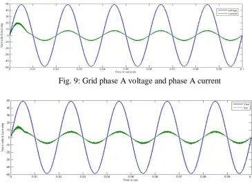
The dc link capacitor is charged to 550V at that time STATCOM operates well which is shown in Fig.9. In this paper fuzzy controller is used so that,it improves the magnitude of the voltages is shown in Fig.10,11, and 13. The controller output is connected to the voltage source converter, voltage gets increases that
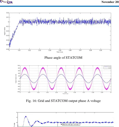
affects on the reactive and active power shown in Fig.12. The Fig.14 and 15 depicts modulation index of STATCOM which is unity and phase angle of the STATCOM is nearly zero respectively. The grid phase A and STATCOM output A voltage is shown in Fig.16. The Fig. 17 shows the change of STATCOM phase A current due to change of load current by an arrow.
Fig. 9: Grid phase A voltage and phase A current
Fig. 10: Grid phase A voltage and STATCOM phase A current
Fig. 12: Active and reactive power of STATCOM
Fig. 13: DC link bus voltage of STATCOM
Fig. 15: Phase angle of STATCOM
Fig. 16: Grid and STATCOM output phase A voltage
Fig. 17: Change of STATCOM phase A current due to change of reference current
V. CONCLUSION
In this paper linear current and voltage controllers for STATCOM control are designed based on fuzzy logic control method to remove fluctuations and also it improves the magnitude of the voltages. The FLC improves power factor by making the phase difference between grid and load nearly to the zero value. The moto of using FLC is to improve the power factor using Reactive power compensation.
power factor improvement and various power quality aspects are also proposed.
REFERENCES
[1] C. L. Wadhwa, Electrical Power Systems, Wiley Eastern Ltd, New Delhi.
[2] P. Kundur, Power System Stability and Control, EPRI, Power Engineering Series, 1994.
[3] M. K. Pal, Voltage Stability Conditions Considering Load Characteristic, IEEE Transactions on Power Systems, Vol.7, No.1, pp.243-249, Feb.1992.
[4] T. V. Cutsem and C. D. Vournas, Voltage Stability analysis in transient and mid-term time scales, IEEE Transactions on Power Systems, Vol.11, No.1, pp.146-154, Feb.1994. [5] T. J. E. Miller, Reactive Power Control in Electrical Systems, John Wiley,1982.
[6] K. R. Padiyar, Power System Dynamics-Stability and Control, Interline Publishing Ltd, Bangalore, 1996.
[7] C. W. Taylor and A. L. V. Leuven, CAPS : Improving Power System Stability Using the Time-Over voltage Capability of Large shunt Capacitor Banks, IEEE Transactions on Power Delivery, Vol.11, No.2, pp.783-792, April 1996.
[8] Y. H. Song and A. T. John, Flexible AC Transmission Systems (FACTS), IEE Power and Energy series Inc. 1999.
[9] N. G. Hingorani and L. Gyugyi, Understanding FACTS, IEEE PES, Sponsor, Standard Publishers Distributors New Delhi, 1999.
[10] R. M. Mathur and R. K. Varma, Thyristor based FACTS Controllers for Electrical
Transmission Systems, IEEE Power
Engineering Society, Sponsorned, Wiley Interscience, 2002.
[11] A. T. Johns, A. Ter-Gazarian and D. F. Wame, Flexible ac transmission systems (FACTS), IEE Power and Energy Series, London, U.K.
[12] R. M. Mathur and R. K. Varma, Thyristors-based FACTS Controllers for
Electrical Transmission Systems, IEEE Press, Wiley-Interscience Publication.
[13] L. T. Moran, P. D. Ziogas and G. Joos, Analysis and Design of a Three- Phase Synchronous Solid-State Var Compansator, IEEE Trans. Industry Application, Vol. 25, No. 4, 1989, pp. 598-608.
[14] C. Shauder and H. Mehta, Vector analysis and control of advanced static VAR compensators, IEE Proc, 140, No. 4, July 1993. [15] M. Sengupta, J. K. Moharana and A. Sengupta, Study on an Advanced Static VAR Compensator switched from a Space Vector PWM inverter-Analysis, simulation and comparison with the conventional sinusoidal PWM, NPEC 2003, IIT Bombay, 16-17 Oct 03 pp. 72-78.
[16] D. M. Brod and D. W. Novotny, Current control of VSI - PWM inverter, IEEE Trans. Industrial Appl, Vol.IA-21, pp.562-570, July/Aug.1985.
[17] S. Buso, L. Malesani and P. Mattavelli, Comparison of Current Control Techniques for Active Filter Application, IEEE Trans. Industrial Electronics, Vol.45, No.5, pp.722-729, October 1998.
[18] S. K. Sethy and J. K. Moharana, Modeling, Design and Simulation of Current and Voltage Linear Controller of a STATCOM for Reactive Power Compensation, NSPEES-12, Sept.29-30, GIET, BBSR, pp. 37-44, 2012. [19] S. K. Sethy and J. K. Moharana, Design, Analysis and Simulation of Linear Controller
of a STATCOM for Reactive Power
Compensation on Variation of DC link Voltage,IEEE transactions on Power energy and control, volume: 28, Issue: 1, pp.74-79, Feb. 2013.
VI. ACKNOWLEDGMENTS
Varsha L. Bade
Varsha L. Bade received her B. E. degree in Electrical Electronics and Power (EEP) from M.B.E. Society’s, College of Engineering, Ambajogai, India,in 2014, and pursuing M.E. degree in Control System Engineering from M.B.E. Society’s, College of Engineering, Ambajogai, India. Currently, She is a Professor in the Department of Electrical Engineering at T.B.G. Polytechnic, Ambajogai, India. Her area of interest covers power system, control system.
E-mail: [email protected]
Ravindrakumar M. Nagarale Ravindrakumar M. Nagarale received his B. E. degree in Instrumentation Technology from P.D.A.College of Engineering, Gulbarga, India, in 1990, and M.E. degree in Instrumentation Engineering from S.G.G.S Institute of Engineering and Technology, Vishnupuri, Nanded, India, in 2006. Currently, he is a Associate Professor in the Department of Instrumentation Engineering at M.B.E. Society’s, College of Engineering, Ambajogai, India. Also, he is Research Scholar at S.G.G.S Institute of Engineering and Technology, Vishnupuri, Nanded- 431606, India. He has published about 10 refereed journal and conference papers. His research interest covers Sliding mode control, and Computational intelligent based sliding mode control. He is a member of ISTE.