PURVIS, ZANED. Using Software Thread Integration with TinyOS. (Under the direction of Asso-ciate Professor Alexander G. Dean).
Wireless sensor network nodes (motes) often spend time busy-waiting while
communi-cating with peripherals such as radios, analog-to-digital converters (ADCs), memory devices, and
sensors. The periods of busy-waiting waste time and energy which are both limited resources for
many mote applications. This document presents techniques of using software thread integration
(STI) in TinyOS applications to reclaim the idle time and use it for useful processing. The TinyOS
scheduler is modified to support the selection and execution of integrated threads and analyzes the
impact of integration on task response time. A microphone array sampling application is used to
demonstrate the savings. Integrated tasks in the sample application finish 17.7% faster and the
by
Zane D. Purvis
A thesis submitted to the Graduate Faculty of North Carolina State University
in partial fulfillment of the requirements for the degree of
Master of Science
Computer Engineering
Raleigh, NC
2007
Approved By:
Dr. Eric Rotenberg Dr. Suleyman Sair
Biography
Zane Dustin Purvis was born June 30, 1979 and grew up in Bennett, North Carolina. He attended
college at N.C. State University (NCSU). While enrolled at NCSU, he was an active officer in
the ACM-AITP and IEEE student branches. He was also inducted into the honor societies of Eta
Kappa Nu (HKN), Tau Beta Pi (TBΠ), and Phi Kappa Phi (ΦKΦ). At his college graduation, he received the honor of “Outstanding Double Major” and obtained bachelor’s of science degrees in
Computer Engineering and Electrical Engineering,summa cum laude. During his graduate career
at NCSU, Zane became active in PackMUG: NCSU’s Apple User Group and a volunteer assistant
for many of NCSU’s scuba courses in the Physical Education Department. Zane has worked for
EMJ Embedded Systems, IBM, Intel, and Sony-Ericsson. He has served as a Teaching Assistant for
computer architecture and embedded systems courses. In addition to his engineering-related work,
he has helped to develop educational materials for the NCSU Academic Aquatics programs. In his
Acknowledgements
Thank you for the help, support, and encouragement of Sandy Bronson, Larry Brown, Paul Bryan,
Matt Craver, Meghan Hegarty, Angel Johnson, Zeb Kaylor, Kyle Luthy, Leonardo Mattos, Dr.
Contents
List of Figures vi
List of Tables vii
1 Introduction 1
2 Related Work 3
2.1 Mote Software Systems . . . 3
2.2 Mote Power Management . . . 4
2.3 Software Thread Integration (STI) . . . 4
3 TOSSTI: TinyOS with Software Thread Integration Support 6 3.1 Description of TinyOS Scheduler . . . 7
3.2 Description of TOSSTI Schedulers . . . 8
3.2.1 Dynamic TOSSTI Scheduler . . . 9
3.2.2 Static TOSSTI Scheduler . . . 10
3.2.3 Scheduler Response Times . . . 12
3.3 Declaring and Posting Merged Tasks in nesC . . . 12
3.3.1 Processing the Application’s C Code and Generating TIDs . . . 14
3.3.2 Declaring Integrated Tasks . . . 15
3.3.3 Using the TOSSTI Script to Generate a TOSSTI Application . . . 15
4 Sample TOSSTI Application 18 4.1 MicSampler TinyOS Application . . . 18
4.1.1 Mote Hardware . . . 18
4.1.2 Software . . . 21
4.2 Finding Tasks . . . 23
4.3 Integrating Tasks . . . 24
4.3.1 Generating AVR Assembly Code . . . 24
4.3.2 Constructing Control Dependence Graphs (CDGs) . . . 25
4.3.3 Performing Software Thread Integration . . . 26
4.3.4 Analysis . . . 28
List of Figures
1.1 Sample mote application timeline without and with STI . . . 1
3.1 TOSSTI Toolchain . . . 7
3.2 Diagram of TinyOS scheduler . . . 8
3.3 Diagram of Dynamic TOSSTI scheduler . . . 9
3.4 Diagram of Static TOSSTI Scheduler . . . 11
4.1 Photo of homemade Mica2 mote . . . 19
4.2 Photo of homemade MicaZ mote . . . 20
4.3 Wiring the CC2420EM module to a breadboard. . . 21
4.4 MicSampler software components . . . 21
4.5 CDG forgetSamplesTask . . . 25
4.6 CDG forstartSend . . . 26
4.7 CFG forstartSend, showing cross-jumping . . . 27
4.8 CDG of IntegratedgetSamplesTaskandstartSend . . . 28
4.9 Oscilloscope screenshots of task execution times . . . 29
4.10 Oscilloscope screenshots of active time using dynamic scheduler . . . 29
List of Tables
Chapter 1
Introduction
The nodes of common wireless sensor networks (WSNs)motesoften have frequent
peri-ods of busy-waiting: communicating with radios, communicating with sensors, communicating with
flash memory, etc. The wait times in these situations is so small the that cost of a context switch to
another task is prohibitive, but useful work could be performed during those times using Software
Thread Integration (STI). STI is a compiler technique for producing fine-grained concurrency on
processors without additional hardware for fast context switches [8]. The motivation behind the
work discussed in this document is to provide a software system to ease the use of STI with a
com-mon wireless sensor network (WSN) operating system. Figure 1.1 illustrates how STI can be used
Time
Mote Application
Transmit integrated with Processing
Mote Application with STI Transmit
Sensing Processing Transmit Idle
Integrated Code
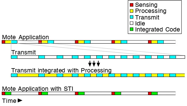
Figure 1.1:Sample mote application timeline without and with STI
to reclaim the idle time that is common when communicating with the mote radio to more efficiently
doing sensing, processing data, and transmitting data followed by a relatively long idle time where
the mote goes to a low-power mode. Inside the Transmit task there are many small windows of idle
time where the processor is simply waiting for a response back from the radio. After integrating the
Transmit and Processing tasks using STI, the idle time that had been present in the Transmit task is
replaced with useful work from the Processing task. Because in the STI-version of the application
Processing and Transmit tasks are interleaved with each other, the two tasks are completed earlier
than if they had been executed serially, as in the original application. Since all tasks are completed
sooner, the processor can go to a low power mode sooner, thus improving energy conservation. Idle
time spent communicating with other SPI-connected peripherals and waiting for ADC results can
also be reclaimed. By more efficiently using the mote’s active time, the mote’s idle time can be
maximized resulting in increased battery life.
Chapter 2 discusses other research on software systems for wireless sensor networks,
power and energy management for wireless sensor networks, and STI. Chapter 3 describes a
soft-ware system for easily using STI with TinyOS applications. Chapter 4 describes an application built
Chapter 2
Related Work
Wireless sensor networks are currently a very active area of research for computer
engi-neers, computer scientists, electrical engiengi-neers, and network engineers. Major areas of research and
development include hardware systems, software systems, and power management.
2.1
Mote Software Systems
Several software libraries or so-called operating systems are available for wireless sensor
networks.
One popular and promising mote operating system is MANTIS (MultimodAl NeTworks
of In-situ Sensors). MANTIS is a project of the University of Colorado at Boulder. It provides a
Unix-like concurrency module [23] and is coded in standard C code [20].
The Contiki operating system is, like MANTIS, coded in standard C, but uses protothreads
for much of its concurrency [9]. Protothreads are lightweight stackless threads that ease the writing
of blocking event-handlers by eliminating/hiding complex state machines [10][11]. Contiki uses an
IP networking stack [21].
TinyOS is the current platform of choice for sensor network research [20]. TinyOS is
programmed using nesC (Networked Embedded System C) and uses a simple run-to-completion,
first-in-first-out concurrency model for any computations that may be time-consuming [14]. Tasks
may be preempted by a hardware event, however, as expected. TinyOS’s designers try to make
hardware differences between mote platforms invisible to the programmer. Several methods are
employed by TinyOS to mask hardware differences from the programmer and provide platform
independence for applications:
• hardware-specific files are separated from platform-generic files
• generic names are given to hardware-specific registers and variables
• a stateless hardware presentation layer (HPL) provides abstracted hardware access [15][12]
[20] discusses the interaction of network layers in TinyOS, the various networking and
abstraction layers, and how power management is used by various network stack implementations.
For an excellent description of current operating systems available for wireless sensor
networks, see [21].
2.2
Mote Power Management
Power and energy management for motes is an active area of research because motes are
deployed in remote locations for long periods of time without changes of batteries. In order to
maximize the lifetime of a wireless sensor network (WSN), power management, energy efficiency,
and power source are considerations that anyone deploying a WSN must consider.
Researchers and developers of WSNs seek to save power by employing various
tech-niques. [16] analyzes the power management facilities provided by various small microprocessors,
such as those used in motes. Various non-battery energy sources for WSN energy scavenging are
suggested in [26].
Using energy-mindful MAC and routing algorithms are also common themes in WSN
research. [20] compares power management techniques used by various network stack
implemen-tations available for TinyOS. [4] describes the SEESAWMAC protocol that attempts to maximize the lifetime of a WSN by using an asynchronous-asymmetric MAC protocol where nodes may take
on one of three roles in the network, depending on traffic patterns. [5] describes X-MAC, a very
clever MAC suitable for use with packetized radios like the Chipcon CC2420 which uses preamble
packets and acknowledgements to shorten the active listening time of the motes and makes up for
many of the shortcomings of B-MAC which relies on radios with lower power listening mode [25].
2.3
Software Thread Integration (STI)
Software Thread Integration (STI) is a compiler technique for producing fine-grained
con-currency on processors without additional hardware for fast context switches at the expense of larger
switches [7]. STI has been used for hardware-to-software migration (HSM), where relatively small
sections of idle waiting are common [8]. Chapter 2 of [8] describes in detail the process of
perform-ing STI usperform-ing program dependence graphs (PDGs). [6] describes an HSM application of STI for
generating video signals.
In [13], STI is used in the kernel of AvrX to perform cryptographic operations (RC4 and
RC5) during TDMA communication, using the idle time between scheduled communication events
to perform computations.
Venugopalan uses STI to improve energy efficiency of motes in [30]. However, his system
uses MCU to MCU communication via SPI, rather than using actual radios. He instead used the
radio’s data sheet to calculate power consumption characteristics, though his MCU-to-MCU system
did not completely simulate communication with a radio — only data transmission. His system also
Chapter 3
TOSSTI: TinyOS with
Software Thread Integration Support
TOSSTI is a tool set for easily adding facilities for Software Thread Integration (STI) to
TinyOS. It includes methods for:
• replacing the default TinyOS 1.1.xscheduler
• declaring nesC tasks that may be integrated with other nesC tasks
• processing a TinyOS application’s code to add STI functionality
When using TOSSTI, the ability to run the non-integrated version of the application and be
de-bugged using the standard TinyOS tools is maintained.
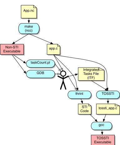
Figure 3.1 gives a graphical overview of the tools used when building an application using
TOSSTI:
• the TinyOS application is developed using nesC and compiled using the standardmaketools included with the TinyOS distribution
• the application is executed and analyzed by the programmer using a debugger and task
anal-ysis tools to determine what tasks are good candidates for STI
• the programmer addsTOSSTImark-ups to the original TinyOS application, and rebuilds
• tasks are integrated using thrint, integrated tasks are declared in an ITF file, and the
applica-tion is processed by the TOSSTI script include the TOSSTI scheduler
App.nc
make (ncc)
app.c
taskCount.pl
GDB Integrated Tasks File (ITF)
TOSSTI
tossti_app.c thrint
gcc
TOSSTI Executable Non-STI
Executable
STI Code
TinyOS Application
Figure 3.1: Interaction of tools used when building a TOSSTI application
This chapter will describe the default TinyOS scheduler, the two TOSSTI schedulers, how
to STI tasks are declared in nesC, and processing a TinyOS application’s code to generate an STI
version of the application.
3.1
Description of TinyOS Scheduler
The scheduler used by TinyOS 1.1.xworks as a FIFO queue, running each task to
comple-tion. There is no notion of priority among tasks and no task can preempt another task. The only way
a running task can be preempted is by an interrupt being serviced. These interrupt service routines
are the only form of concurrency available in TinyOS 1.1.x.
In order for TinyOS to support integrated threads, there must be a way to recognize which
tasks have been integrated, and the TinyOS task scheduler must be modified to identify when an
integrated version of several tasks is available and run it.
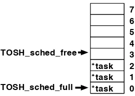
The TinyOS 1.1.x scheduler is implemented as a circular FIFO queue and a call to
TOSH_run_next_task()executes and removes the function at the head of the task queue. The queue is implemented as an array (TOS_queue) of C structs with a single field tp, which is a pointer to a task. Figure 3.2 shows a conceptual diagram of the TinyOS scheduler. Tasks are
*task *task *task
7 6 5 4 3 2 1 0 TOSH_sched_full
TOSH_sched_free
Figure 3.2:Diagram of TinyOS scheduler
two variables: TOS_sched_fullis the array index of of the first used position of the queue, and
TOS_sched_freeis the array index of the first free entry in the queue. The first task to be executed is atTOS_queue[TOS_sched_full]. IfTOS_queue[TOS_sched_free].tpis non-null, then the queue is full; otherwise, a new task is added to the queue with the code
TOS_queue[TOS_sched_free].tp = function_name;. The size of the queue is defined with the constantTOSH_MAX_TASKS, which must be a power of two for efficient modulo arithmetic for wrapping the array indexes beyond the size of the array.
3.2
Description of TOSSTI Schedulers
In order to run integrated threads in TinyOS, the scheduler must be modified to
deter-mine when an integrated version of multiple tasks is available. Previous schedulers for STI systems
utilized two queues because there was an obvious distinction between host/primary and
guest/sec-ondary threads: a task would only be posted to the queue to which it belonged, and only the heads
of the two queues would be examined when determining whether an integrated version of threads
should be executed [6][13][30][31]. This design has anO(1)scheduler. In a multi-queued system, one queue may constantly have fewer tasks in it, resulting in that category of task getting an
arti-ficially higher priority. A multiple-queue scheduling system would break TinyOS’s single-priority
scheduling semantics because tasks in the consistently shorter queue would get an artificially
ele-vated/reduced priority. This may lead to starvation problems. In TOSSTI, like the TinyOS default
scheduler, a single queue is used for all tasks. By using a single queue, the developer does not
need to worry about classifying each thread in the system into a category. More importantly, in
the single-queued system, starvation problems are eliminated and TinyOS’s nesC task scheduling
semantics and syntax do not need to be changed.
and a static scheduler.
3.2.1 Dynamic TOSSTI Scheduler
In the dynamic TOSSTI scheduler, the TinyOS functionTOSH_run_next_task()has been replaced withTOSSTI_run_next_task()and theTOS_queuearray has been replaced by
TOSSTI_queue, which is similar toTOS_queueexcept it is an array ofTOSSTI_sched_entry_t
type structures. The definition ofTOSSTI_sched_entry_tis shown below: struct TOSSTI_sched_entry_st {
void (*tp)(void); ///< pointer to the task.
uint8_t tid; ///< Task ID. 0 if not TOSSTI
bool has_run; ///< Has this task already been run?
};
typedef struct TOSSTI_sched_entry_st TOSSTI_sched_entry_t;
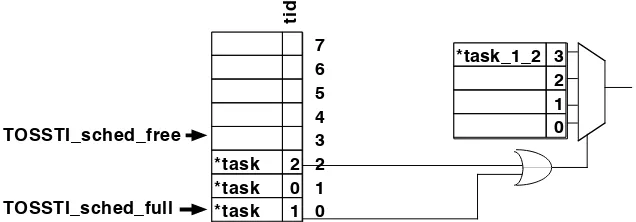
Thetpfield is the same as in the TinyOS scheduler and is simply a pointer to a task/function to be executed. ti d 7 6 5 4 3 2 1 0 *task_1_2 3 2 1 0 *task 2 *task 0 *task 1 TOSSTI_sched_full TOSSTI_sched_free
Figure 3.3: Diagram of Dynamic TOSSTI scheduler
Figure 3.3 shows a conceptual diagram of how the dynamic TOSSTI scheduler works. In
the dynamic TOSSTI scheduler, atidfield has been added to serve as a unique identifier for each integrated task. When determining what task to run, the dynamic TOSSTI scheduler looks at the
head of the queue (TOSSTI_queue[TOSSTI_sched_full]). If that entry has atidof0, then the task is removed from the queue and executed just like in the TinyOS scheduler. However, if thetid
field is non-zero, it continues searching the queue for another thread with a non-zero tid, which may have been integrated with the task. If the scheduler finds another task with a non-zerotid, the values of thetidfields are bitwise-ORed together and the result is used as an index into the
TOSSTI_integrated_threads array. If that position of theTOSSTI_integrated_threads
in theTOSSTI_integrated_threadsarray which should be executed. The scheduler continues searching for another thread until there are no more integrated tasks in the queue.
Because the search for integrated tasks extends beyond the head of the queue, if an
in-tegrated version of several tasks is found and executed, then the tasks will no longer be executed
in a FIFO order. Rather than remove each of the tasks that have been executed by the integrated
thread, a has_runflag is used to indicate to future invocations ofTOSSTI_run_next_task()
that a task has already been executed out-of-order. Later, whenTOSSTI_run_next_task()looks at the head of the queue, and finds that the task has already been run, it simply removes that entry
from the queue and returnstrue, signaling the caller that it actually did execute a task. Using the
has_runflag to defer removing executed tasks until later saves the clock cycles that would have otherwise been used to shift other tasks in the queue forward when the executed task is removed.
So that the scheduler does not waste time searching the queue for other integrated tasks
when there may not be any, a bit-map called “TOSSTI_locator” is used to indicate the relative po-sition of TOSSTI-tasks in the queue. Bit 0 ofTOSSTI_locatorcorresponds to whether the task at the head of the queue is a TOSSTI-task: a zero indicates that it is a traditional (never integrated) task,
a one indicates that it was declared as an integrated task. (More on declaring TOSSTI-tasks in nesC
can be found in section 3.3.) Each time a task is removed from the queue, theTOSSTI_locator
is right-shifted by one. Whenever a task is added to the queue, the bit corresponding to the
po-sition of the new task with respect to the head of the queue is set if the task has a non-zerotid.
TOSSTI_locatoris used as a boolean to stop the queue search for another integrated task and is used to determine which positions in the queue to search for an integrated task. This scheduler has
a worst-case runtime complexity ofO(n).
When compared to the standard TinyOS scheduler, the dynamic TOSSTI scheduler uses
2×more RAM for queue storage on the AVR architecture, but that is actually relatively minimal
when considering that instead of two bytes per queue entry as in TinyOS, TOSSTI uses only four
bytes, plus one additional byte for the locator bitmap, when using the default queue size of eight.
The lookup table that stores the addresses of integrated tasks also requires two bytes per entry, but
could be stored in program memory or ROM in systems where tasks do not get added at runtime.
3.2.2 Static TOSSTI Scheduler
A second scheduler for using STI with TinyOS has been developed, called the static
and which integrated version of tasks should be executedwhen the scheduler is fetching a new task
from the queue. The static scheduler, however, modifies the queue to include the integrated versions
of taskswhen a task is posted. The static scheduler’spostfunction uses a static C array, with one element for each task that has been declared as a TOSSTI task in the system. The array is indexed
using a task’s tid and is used to store the position in theTOS_queuearray where the previous instance of the posted task was stored. If a new task is being posted to the scheduler, and a task that
it has been integrated with has been posted and is still in the queue, the previously posted task’stp
field in the queue is updated to point to the STI version of the tasks, rather than the discrete version
of the task, by thepostfunction. Aside from changes in thepostoperation, all of TinyOS’s other scheduling functions and data structures remain unchanged when using the static TOSSTI scheduler.
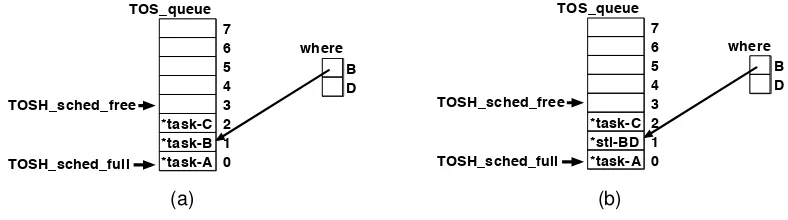
7 6 5 4 3 2 1 0 *task-C *task-B *task-A TOSH_sched_full TOSH_sched_free B D where TOS_queue 7 6 5 4 3 2 1 0 *task-C *sti-BD *task-A TOSH_sched_full TOSH_sched_free B D where TOS_queue 7 6 5 4 3 2 1 0 *task-C *task-B *task-A TOSH_sched_full TOSH_sched_free B D where TOS_queue 7 6 5 4 3 2 1 0 *task-C *sti-BD *task-A TOSH_sched_full TOSH_sched_free B D where TOS_queue (a) (b)
Figure 3.4: Scheduler queue before (a) and after (b) posting an integrated task, task-D, to the
static TOSSTI scheduler
Figure 3.4 illustrates what occurs when a TOSSTI task is added to the static TOSSTI
scheduler. In this particular application, there exists a task namedsti-BDwhich is an integrated version of taskstask-Bandtask-D. In figure 3.4a, you can see the status of the scheduler queue and thewherearray after three tasks have been posted:task-A,task-B, andtask-C. The entry in thewherearray corresponding to B points to the location in the queue wheretask-Bwas last posted. In figure 3.4b,task-Dhas just been posted, and sincetask-Dis integrated withtask-B, the queue entry fortask-Bhas been replaced with the STI version of the two tasks,sti-BD. The scheduler’spost()function knows thatsti-BDis an STI version oftask-Bandtask-Dbecause it was specified as such in theintegrated tasks filewhich is discussed in section 3.3.2.
The static TOSSTI scheduler uses considerably less RAM than the dynamic scheduler. In
fact, it requires only one additional byte RAM per TOSSTI task than the default TinyOS scheduler.
The code size increase for the static TOSSTI scheduler is also considerably smaller than the dynamic
TOSSTI scheduler when few tasks have been integrated: finding an integrated version of two tasks
3.2.3 Scheduler Response Times
For the original TinyOS FIFO scheduler, ifTiis the execution time of taskiandT0is the
time remaining in the current task, the response time for tasknis shown in equation 3.1.
R(n) =T0+ n X
i=1
Ti (3.1)
For the TOSSTI schedulers, calculating a response time for a task is not quite as simple because
some tasks are removed and replaced as the queue is updated. If I is the set of tasks that have
been placed in the queue before taskn and have been replaced with an STI-version, and S is the
set of integrated (STI) tasks that replaced them, then the response time for tasknusing a TOSSTI
scheduler is as shown in equation 3.2.
R(n) =T0+ n X
i=1
Ti− X
α∈I
Tα+ X
α∈S
Tα (3.2)
3.3
Declaring and Posting Merged Tasks in nesC
The nesC programming language used by TinyOS provides the following syntax for
defin-ing a task named “myReallySweetTask”:
task void myReallySweetTask() {
// a fun mix of C and nesC code here
}
and this syntax for posting the task in the queue to be executed later:
post myReallySweetTask();
As you can see, neither of these allow any sort of argument passing which would be useful to
pass a tid value or otherwise indicate that a task has been merged with other tasks to form an integrated thread [14]. Because the nesC compiler generates C code, a user could hand-modify the
generated C code, picking out all posts of tasks they have integrated and replacing them with posts
that includetids. Hand-modifying the generated C code is less than ideal and does not do a very good job of integrating with the TinyOS application: whenever the application is recompiled, the
hand-modifications will need to be redone. The TOSSTIC preprocessor macro makes it easy to mark integrated tasks.
(Note that using the nesC “includes TOSSTI” directive does not work for this use.) The definition of the task in the nesC code then becomes
task void TOSSTI(myReallySweetTask) {
// a fun mix of C and nesC code here
}
and all posts of the task in nesC become
post TOSSTI(myReallySweetTask);
Any use ofmyReallySweetTaskmust now be wrapped in a call of theTOSSTImacro. If a task is declared usingTOSSTIbut is posted without it (or vice versa), the nesC compiler will issue an error that the task has been “implictly declared” and that “only tasks can be posted” since the task’s
name does not match. The TOSSTImacro mangles the name of the task so that other tools (see section 3.3.1) can parse the C code generated by the nesC compiler and pick out which tasks have
been, or will be, integrated and assign uniquetids to them which will be used by the scheduler. Using the TOSSTI macro will not break any existing TinyOS applications and can be used on any task: there does not need to be an integrated version of it available, yet. The
pro-cess of building and installing anon-integratedversion of a TinyOS application using theTOSSTI
macro is the same as if there were no uses ofTOSSTIin the code. In fact, it is suggested that an application be implemented, completely debugged, and verified with TOSSTI calls in place before
doing any STI on the tasks. The only difference one may notice during the process when
com-pared to a traditional TinyOS application is that in a debugger, instead of seeing a task named as
“MyModule$mySweetTask,” a TOSSTI-task will be named “MyModule$___TOSSTI___mySweetTask___.”
Behind the scenes, nesC’s post operations become calls to theTOS_postC function, which takes the address of the function being posted as its only argument. When using TOSSTI,
all calls toTOS_postbecome calls toTOSSTI_post, which takes two arguments: the address of the function being added to the queue and a task identification number ortid. Each task that has been marked using theTOSSTImacro is assigned a uniquetidwhen the application is being built. Non-TOSSTI tasks are assigned atidof0.
An alternative to providing a macro for declaring integrated tasks is to modify the nesC
compiler to support new methods of declaring and posting tasks. Using a macro, however, allows
anyone to use TOSSTI without applying a patch to their compiler and is less likely to break when
3.3.1 Processing the Application’s C Code and Generating TIDs
With a normal TinyOS application, a developer types “make micaz install” to com-pile and load their application onto their mote (replacing “micaz” with the platform they are using,
of course). When building an STI version of a TinyOS application, however, after writing and
de-bugging the source code using the standard TinyOS tools, the application’s code must be processed
to add the TOSSTI scheduler (discussed in 3.1) and generatetids for the potentially merged tasks. When a TinyOS application is compiled using the standard TinyOS “make” system, a
build/platform/directory is created bymake. That directory contains anapp.cfile, a binary, and various other files. The nesC language is compiled to C as an intermediary, which is dumped
into theapp.cfile. To automate the process of transforming theapp.cTinyOS application to a TOSSTI application with the new scheduler and support for software integrated threads, a script
can be used. The TOSSTI script is written in perl and makes a single pass over theapp.cfile to generate the TOSSTI version of the file.
The TOSSTI script looks for functions declaring TOSSTI-tasks (those tasks that were
declared in nesC with theTOSSTI macro). The nesC compiler generates a function declaration for each task with the prototype “void ModuleName$taskName(void);.” Whenever a single line of theapp.cfile matches this pattern, the TOSSTI script looks for the presence of the string “___TOSSTI___” in thetaskName. If “___TOSSTI___” is found, the script puts the function name (including the module name) into a hash table and assigns the task atid. The hash table is keyed by the function name, and contains thetidas the value. For the dynamic scheduler, thetids are assigned as sequential powers of two (e.g., 1, 2, 4, etc) for the dynamic scheduler.
The TOSSTI script also searches forpostsof tasks. Alltasks posted in a TOSSTI
appli-cation must use the TOSSTI scheduler, instead of the default TinyOS scheduler. The nesC statement
“post workerTask();” is translated to the C statement “TOSH_post(ModuleName$workerTask)” by the nesC compiler. Whenever the script finds a line with a call to TOSH_post(), it replaces it with a call to TOSSTI_post(), with the correct
tidas an argument, using atidof0if the task being posted is a non-TOSSTI task. Because of C’s “declare-before-use” rule, function declarations are found before they are called, sotids have already been assigned by the TOSSTI script before it finds anypostsof the tasks.
The TOSSTI script must insert the declarations and definitions of theTOSSTI_post(),
before the definition of “main” inapp.c. Calls toTOSH_init_sched(), andTOSH_run_next_task()
are replaced with calls to TOSSTI_init_sched() and TOSSTI_run_next_task(), respec-tively. TheTOSSTI script adds C preprocessor line number directives to the output source code to aid in debugging the application.
3.3.2 Declaring Integrated Tasks
After translating the TinyOS function calls inapp.cto the equivalent TOSSTI functions in the output file, the TOSSTI script must define theTOSSTI_integrated_tasksarray which is consulted by the dynamic scheduler to find integrated versions of tasks that have been posted to the
task queue, or generate a customTOSSTI_post()function if using the static scheduler.
To indicate to the TOSSTI tools which tasks have been merged to form integrated threads,
anintegrated threads fileis used. Below is an example of an integrated threads file:
tasks01 = {MyModule$___TOSSTI___task0, MyModule$___TOSSTI___task1} tasks03 = {MyModule$___TOSSTI___task0, MyOtherModule$___TOSSTI___task3}
The first line indicates that an integrated version of task0 of module MyModuleand task1of module MyModule resides in the function named tasks01. The next line indicates task0 of
MyModuleandtask3 ofMyOtherModuleare integrated in the functiontasks03. Note that a task may be integrated with more than one other task, and that tasks do not need to belong to the
same nesC module to be integrated with each other.
Below is the grammar of an integrated tasks file.
integratedTasksFile→integratedTaskDeclaration
→integratedTasksFile integratedTaskDeclaration integratedTaskDeclaration→IntegratedThreadName ={taskNameList};?
taskNameList→TaskName , TaskName
→taskNameList, TaskName
3.3.3 Using the TOSSTI Script to Generate a TOSSTI Application
After compiling the TinyOS application with the calls to the TOSSTI macro wrapped around potentially integrated task names, a developer will want to run the TOSSTI script to see
which tasks have been marked and build the TOSSTI version of the application. Rather than
re-placing thesched.cfile in thetos/system/directory, TOSSTI stores the equivalent functions in theTOSSTI.cfile and the TOSSTI script inserts them into the TinyOS application after it has been compiled to C by the nesC compiler. This eliminates the need to change files in the user’s TinyOS
The TOSSTI script takes several parameters:
–application=input path specifies the path to the nesC generated app.c file for the application be-ing built. This will generally bebuild/micaz/app.c
–output=output path specifies the path to where to output the TOSSTI version of the application. For example,--out=build/micaz/tossti_app.c.
–tids=output path specifies the path to where to output a list of task names and thetids that have been associated with them.
–integrated-tasks=input path specifies the path to the integrated tasks file describing which tasks have been merged with other tasks. See section 3.3.2.
–dollars=replacement text specifies the string used to replace the$symbol in identifier names. $
is not valid for identifiers in AVR assembly code, so by default, TOSSTI replaces occurrences
of ‘$’ with “___”. Use this option to change the substitution. To leave the$’s in the code, use--dollars=’$’.
–verbose has the script run in verbose mode, displaying information that may be useful for debug-ging.
The arguments can be abbreviated as long as the abbreviation is unique. For example, instead of
typ-ing “--application=build/micaz/app.c,” the abbreviation “--app=build/micaz/app.c” can be used.
The applicationparameter is always required, the other parameters are optional and are used only when necessary.
Immediately after building a TinyOS application, a developer will probably want to get a
list of the TOSSTI tasks. This can be done with the command
TOSSTI --application=build/micaz/app.c --tid=tossti_thread_ids.tid
A list of tasks read fromapp.calong with their associatedtids will be dumped to a file named “tostti_thread_ids.tid.” Thetids are listed only for aid in debugging the integrated appli-cation and the identifiappli-cation numbers should not be used by the developer except when debugging.
Instead, the task names should be consulted when constructing the integrated threads file.
After constructing an integrated threads file, the developer will want to generate C code for
their TOSSTI application. This is done with the command
--int=TOSSTIDemo.itf
Here, the integrated threads input file is named “TOSSTIDemo.itf.” The TOSSTI version of the application will be saved in “tossti_app.c” with the TinyOS scheduler replaced with the TOSSTI scheduler along with the array of integrated tasks. It is then up to the developer to compile
Chapter 4
Sample TOSSTI Application
4.1
MicSampler TinyOS Application
A TinyOS application named “MicSampler” has been devised to demonstrate using STI in
TinyOS with TOSSTI. MicSampler is roughly based on the microphone array sampling application
described by Luthy in [19]. Luthy’s application periodically samples eight microphones attached
a mote’s analog to digital converter (ADC), and sends those samples to a PC which calculates the
direction of a sound detected within a specific frequency range. This has both military and civilian
applications, and could be used as a method for acoustically determining the relative locations of
other motes in a network, or for aiding people with disabilities [3]. The differences in Luthy’s mote
application and the MicSampler implementation are described below.
The time between reading sets of samples is assumed less important than the time spent
between reading each sample from the ADC. That is, each microphone must be sampled as quickly
after the previous microphone sampling as possible in order to approximate an instantaneous
sam-pling and be able to determine while direction a sound is emanating from.
4.1.1 Mote Hardware
Luthy used a Ren´e mote in his application. The mote used in this project is modeled after
a micaZ due to the more modern design and availability of parts and software. Currently, the micaZ
is the state-of-the-art mote available for research, though the TI MSP430-basedtelosortmotesare
also used. The micaZ and the tmotes use the CC2420 radio. The micaZ is better suited for this
project than the tmotes because the micaZ is based on on AVR MCU, and existing software tools to
file also may arguably make register allocation for STI easier than the MSP430’s 16 [28].
The Ren´e mote Luthy used is based on the now-deprecated Atmel 90LS8035 AVR
micro-controller, running at 4 MHz and uses the TR1000 radio from RF Monolithics [19]. Originally, this
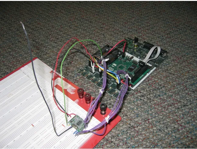
project used a homemade Mica2 mote, which uses an Atmel ATmega128 microcontroller running
at 4 MHz, Atmel STK-500, Atmel STK-501, and Chipcon CC1000 radio because we already had
parts to build one, and a schematic was available from Crossbow [17][22]. A photograph of one of
the homemade Mica2 motes can be seen in Figure 4.1. Although a Mica2-like mote was used to
ini-Figure 4.1: Homemade Mica2 mote, using STK500, STK501, ATmega128, and CC1000EM.
tially test out TinyOS and determine how suitable it would be for supporting STI, it was determined
that a more modern mote architecture might be a better example of using STI in WSNs.
While the mica2 mote has a schematic publicly and freely available, there was no such file
available for the more modern micaZ mote. However, by examining the uses of the
TOSH_ASSIGN_PIN macros in the TinyOS software directory
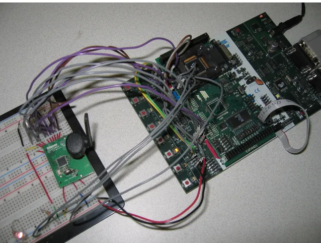
...tinyos/platform/micaz/hardware.h, the ATmega128 physical interface to the CC2420 radio can be determined to be as shown in Table 4.1. A photo showing the homemade mote using
the CC2420 radio can be seen in Figure 4.2. Because the socket on the underside of the CC2420EM
module are not common headers, 16 gauge wire was used to make the evaluation module compatible
Table 4.1:Wiring interface of ATmega128 to CC2420
CC2420EM Pin CC2420 Pin AVR Pin Use
P1-3 41 A5 VREG EN
P1-5 21 A6 CC RSTN
P1-6 30 B7 CC FIFO
P1-8 29 E6 (INT6) CC FIFOP / CC FIFOP1
P1-10 28 D6 RADIO CCA (clear channel assessment)
P1-12 27 D4 CC SFD (start of frame detected)
P1-14 31 B0 CC CS
P1-16 32 B1 SPI SCK
P1-18 33 B2 MOSI
P1-20 34 B3 MISO
P2-9 VTG 3.3 V
P2-20 GND Gnd
Figure 4.3:Wiring the CC2420EM module to a breadboard.
4.1.2 Software
Luthy’s mote was programmed using AVR assembly language. The demonstration
appli-cation for this project was written in nesC to take advantage of and showcase the use of existing
TinyOS modules and tools. Some time-critical parts were written using inline AVR assembly.
Overview of MicSampler Application
Main
MicArrayM StdControl
MicSamplerM StdControl
MicArray
MicroTimerM MicroTimer
LedsC Leds
GenericComm StdControl
SendMsg
ReceiveMsg
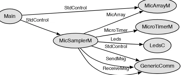
Figure 4.4: Components used in MicSampler as generated using nesdoc
is configured to signal an interrupt periodically, at desired the sample rate. Whenever that interrupt
occurs, the TinyOS signal MicroTimer.timerFired is executed which does two things: read all eight channels from the AVR’s ADC and transmit the eight ADC samples from the previous
sample period over the mote’s CC2420 radio. The sample and transmit operations are performed in
TinyOS tasks. Figure 4.4 shows the component interaction diagram generated for the MicSampler
application by thenesdoctool.
Description of MicSampler Files
MicSampler consists of four original nesC files: MicSampler.nc, MicSamplerM.nc,
Mi-cArray.nc, and MicArrayM.nc. It also uses modified versions of the TinyOS CC2420RadioM.nc,
HPLCC2420M.nc, and the HighFrequencySampling demo application’s MicroTimerM.nc. It also
consists of the C header file MicArrayMsg.h.
MicSampler.nc Configuration describing the components of the application, and wiring between them.
MicSamplerM.nc Module implementing the interfaces indicated in MicSampler.nc and implemen-tation of top-level program logic.
MicArray.nc Interface describing the basic interface (commands and events) required to be imple-mented by a MicArray component.
MicArrayM.nc Module implementing each of the commands specified in MicArray.nc using the on-chip ADC of the ATmega128 of a micaZ mote.
CC2420RadioM.nc Modified from the standard TinyOS system file to include the TOSSTI markups and with no software-based initial back-off when preparing to transmit.
MicroTimerM.nc Modified from the demonstration HighFrequencySampling TinyOS application so that the microsecond-resolution timer can be used at the same time as the micaZ’s CC2420
radio, a limitation in the demo application.
4.2
Finding Tasks
After the basic TinyOS version of MicSampler was designed, coded, and tested, the
TOSSTI version was made. The first step in creating the TOSSTI version was determining what
tasks were in the system, and which ones to integrate. TinyOS includes a tool for listing tasks in a
system,taskCount.pl, which claims, “Until we have ‘ps,’ we might as well have this.” To find a list of tasks in the current TinyOS application directory use the command
../../tools/scripts/taskCount.pl micaz.
It will list all the tasks in the application. For the MicSampler application, the following was
dis-played:
Addr Name
0x1190 AMStandard.sendTask
0x285e CC2420ControlM.PostOscillatorOn 0x8d4 CC2420ControlM.taskInitDone 0x222e CC2420RadioM.PacketRcvd 0x2206 CC2420RadioM.PacketSent 0x14e6 CC2420RadioM.startSend
0x1e90 CC2420RadioM.delayedRXFIFOtask 0x32d6 FramerAckM.SendAckTask
0x3210 FramerM.PacketRcvd 0x133a FramerM.PacketSent 0x333c FramerM.PacketUnknown
0x1fde HPLCC2420FIFOM.signalRXdone 0x163a HPLCC2420FIFOM.signalTXdone 0x2a7e HPLCC2420M.signalRAMWr
0xd2a HPLPowerManagementM.doAdjustment 0x1a24 MicArrayM.getSamplesTask
0x10b2 MicSamplerM.timerFiredTask 0x253e TimerM.HandleFire
0x26fa TimerM.signalOneTimer 19 tasks
After listing the tasks in the system, to determine which tasks were ready to run at the
same time, one can set a breakpoint at each task usinggdband the Atmel JTAG In-Circuit Emulator (JTAG-ICE). When the breakpoint is reached, usegdb to print theTOSH_queuearray and make note of which tasks are consistently present in the queue at the same time. Those tasks are good
candidates for integration if they meet the following requirements:
• have fine-grained internal idle time, such as busy-wait loops
• looping constructs execute a known number of times
• function calls inside the task can be inlined[8]
Code consisting of busy-wait loops are common in tasks that communicate with the radio (transmit
and receive) code that communicates with common sensors attached to the SPI bus, and external
Flash memory. Tasks that read from the ADC also commonly have busy wait loops: on the AVR
architecture the on-chip successive-approximation ADC can take 14 ADC clock cycles to perform
a conversion, depending on how it is configured [1]. Looping constructs beyond the region to
be integrated can have an indeterminate number iterations: only loops that overlap with the other
thread during integration need to have known iteration counts. The same holds true for function
calls beyond the integration region.
Changes to MicSampler Application for TOSSTI
The sample-reading task (getSamplesTask) and the TinyOSCC2420FIFOM.startSend
tasks were marked with theTOSSTImacro to indicate that there may be a version of them existing in the system that has been integrated with another task. If, during compilation, theTOSSTI.pl
script is used, then a TOSSTI-enabled application can be generated, otherwise, if only the standard
TinyOS build tools are used, the application is built without STI enabled.
4.3
Integrating Tasks
4.3.1 Generating AVR Assembly Code
For the MicSampler application, the tasks CC2420RadioM$startSend and
MicArrayM$getSamplesTask were ready to run at the same time, so they were good candi-dates for integration. After picking out which tasks to integrate, assembly code for those
func-tions was necessary. To generate assembly code for the tasks, avr-gcccan be used to compile
build/micaz/app.c. However, ncc, the nesC compiler front end generates C code with$’s in identifiers. Since$is used to indicate hexadecimal numbers in AVR assembly language, those cause problems when compiling. To remove them, either the TOSSTI script can be used, or the command
can be used. The same optimization options used by the TinyOS build system are used:
-Os -finline-limit=10000.
4.3.2 Constructing Control Dependence Graphs (CDGs)
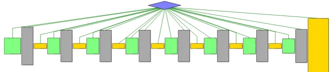
Figure 4.5:CDG forgetSamplesTask
Generating the control dependence graph for getSamplesTask was relatively easy:
getSamplesTaskis straight-line code. Its control dependence graph can be seen in Figure 4.5:
• green nodes indicate basic blocks that start an ADC conversion and write an ADC value to
memory
• gold blocks are the ADC read operations
• gray blocks arenops used to pad away busy-waiting
Generating the control dependence graph forstartSendwas not as easy. First of all, the
startSendtask called several functions which needed to be inlined before the control dependence graph (CDG) could be generated usingthrint[29]. Modifying theapp_free.cfile so that func-tions called bystartSendwere inlined by usinggcc’s__attribute__((always_inline))
on the function declarations of called functions helps to eliminate thecallinstruction, and makes integration easier. An alternative to usinggcc function attributes is converting the function to a C-macro. The startSend task called several functions which needed to be inlined before the control dependence graph (CDG) could be generated using thrint. The declarations for each ofstartSend’s called functions were modified untilgccwould inline them, except for the call to
TOS_post, which came only at the function’s end, and would not interfere with control dependence graph construction.
When using gcc to compile a single function to assembly for use as one of the threads to
integrate, be sure to specify -finline-limit=10000 and -Wall. The GCC
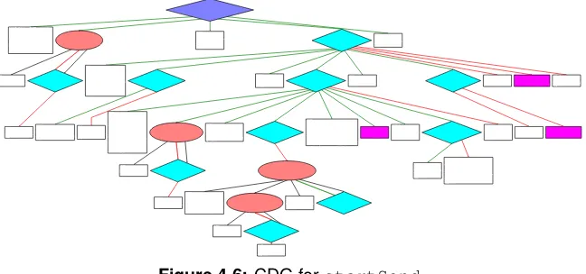
Figure 4.6: CDG forstartSend
After inlining called functions,thrintis used to construct the CDG forstartSendas is seen in figure 4.6:
• blue diamonds represent predicate nodes
• pink ovals represent the entry of a loop, with the conditional in a predicate node below it
• magenta nodes are function calls that were not inlined
• white nodes are simply code blocks
While usingthrintto construct the CDG it was noticed that one of the optimizations included withavr-gcc’s-Osoptimization setting sometimes generates unstructured code that the version of thrint used for this project cannot understand, although work is being done to add restructing capabilities tothrint. Luckily, when the-fno-crossjumpingoption was passed to
gccwhen compilingstartSendto assembly code,thrintwas able to accept the code as input. To illustrate how cross-jumping affects the control flow of the code, figure 4.7 shows the control
flow graphs ofstartSendwith and without cross-jumping enabled: (a) has a jump into a decision (ID) [24] which does not occur in (b) when cross-jumping is disabled.
4.3.3 Performing Software Thread Integration
startSend_orig L881 L881_0 L881_1 L881_3 L881_2 L881_4 L890 L917 L877 L891 L891_0 L891_1 L916 L897 L894 L897_0 L897_1 L907 L915 L904 L915_0 L910 L904_0 L904_1 Exit startSend_nocrossjumping L870 L870_0 L870_1 L867 L870_2 L867_0 L879 L866 Exit L880 L880_0 L882 L883 L886 L883_0 L886_0 L886_1 L896 L904 L893 L899 L904_0 L893_0 L893_1 (a) (b)
Figure 4.7: CFG ofstartSendwith(a), andwithout(b) cross-jumping optimization
Because TinyOS/nesC tasks take no arguments, and return void, when doing register
allo-cation, you do not need to worry about calling functions placing arguments in certain registers, and
you can use the return registers without concern.
Modifications togetSamplesTaskfor STI
The function getSamplesTaskrequired no changes for STI that were not done previ-ously for timing purposes: busy-wait loop unrolling, and software pipelining. When the CDG was
generated bythrint, however, the start cycle of actual code blocks (as opposed to blocks ofnops) was noted so that it could be determined where instartSend’s CDG to insert each code node.
Also, the register file was partitioned so that register uses would not collide with registers
used by thestartSendfunction. Register use was limited as much as possible, without affecting real-time constraints within the function.
Modifications tostartSendfor STI
The functionstartSend, in contrast togetSamplesTask, had many busy-wait loops, as well as a loop over the elements of an array (the bytes of the packet to be transmitted over
and CC2420 radio were consulted as well as experimentally testing with varying numbers ofnops until the exact number of clock cycles to complete the SPI writes was known [1][2]. The CDG
was, of course, reconstructed after unrolling the busy-wait loops. As each of the code nodes from
getSamplesTaskwas inserted intostartSend’s CDG at the correct cycle,getSamplesTask
code from nodes that overlapped with thenops fromgetSamplesTask’s unrolled busy-wait loops could replace thosenops. Also, becausestartSendhas a loop over each byte in the array which runs at a frequency other thangetSamplesTask’s reads of ADC channels, the loop needed to be peeled five times for the guest code nodes to be inserted at the correct cycles.
Manually using register partitioning for startSend was more complicated than that for getSamplesTaskbecausestartSendhad to avoid overlapping register uses with those of
getSamplesTask. Using the command
avr-gcc -S -Wall -finline-limit=10000 -mmcu=atmega128 -fno-crossjumping -Os -ffixed-Z -ffixed-r0 -ffixed-r1 -ffixed-r18 -ffixed-r19 -ffixed-r20 -ffixed-r22 -ffixed-r24 -ffixed-r25 -ffixed-r30 -ffixed-r31 tossti_app.c
partitioned the registers enough that once the two functions were integrated, there was only one
case of a register definition made bygetSamplesTaskcolliding with a register definition made by
startSend. Luckily, the value in the register was a constant used by startSend that
getSamplesTaskoverwrote. Another ldi instruction was inserted before the use of that con-stant so that the integrated function would function correctly.
Figure 4.8 shows the CDG of the software thread integrated version of the two functions.
Figure 4.8: CDG of IntegratedgetSamplesTaskandstartSend
4.3.4 Analysis
Figure 4.9 shows oscilloscope screenshots of the time required to execute the tasks
(a) (b)
Figure 4.9:Oscilloscope screenshots showing task execution time (a) without and (b) with STI
on a single output pin on the MCU when the task began execution, and turned off just before that
task’sretinstruction was executed. You can see from (a) thatgetSamplesTasktakes 77.7µs to execute andstartSendtakes 200.5µs, for a total of 278.2µs, including the time required to toggle the output pins. (b) shows that the integrated version ofgetSamplesTaskandstartSendtakes only 229.0µs to execute. When compared with the discrete versions of the threads, the integrated
tasks show a 17.7% reduction in run time.
Active Time Analysis
(a) (b)
Figure 4.10:Oscilloscope screenshots showing active time (a) without and (b) with STI using
dy-namic TOSSTI scheduler
After verifying the speed improvement of the integrated task compared to the discrete
tasks, the time the processor was active was measured. To do this, an output pin was turned on
when the processor woke up from a sleep mode, which involved modifying each interrupt service
processor (a) without TOSSTI and (b) with TOSSTI while using the dynamic TOSSTI scheduler.
The bottom-most waveform, labeled “ACTIVE” shows the active time of the processor, and one can
see that its width is (a) 514.0µs when not using TOSSTI, and (b) 566.5µs when using TOSSTI:
that means anincreasein active time when using STI rather than the expectedreduction! When
looking at how much time is spent actually spent searching for the next task to execute (waveform
“SCHED”), (b) which uses STI spends over twice as much time as (a) which is the plain TinyOS
im-plementation of the application. For this application, the runtime overhead of the dynamic TOSSTI
scheduler negates the benefits of using STI. In an application with longer tasks, this overhead may
be negligible, but since there are many applications where the tasks are short, the runtime overhead
needed to be reduced for STI to be feasible for WSN applications. This realization is actually what
led to the development of the static TOSSTI scheduler which is described in section 3.2.1.
Figure 4.11:Oscilloscope screenshot showing MicSampler application usingstatic TOSSTI
sched-uler
After the static TOSSTI scheduler was developed, the active-time analysis was done
again. Figure 4.11 shows the active time of the same application using STI and the static TOSSTI
scheduler is 481.5µs. When compared to the non-STI version of the application as seen in
fig-ure 4.10a, that is a time savings of 32.5µs or a decrease of 6.3%. By running the integrated version
of the threads rather than the discrete versions using the static TOSSTI scheduler, the processor
can go back to a sleep mode 6.3% sooner with this application. With other applications,
includ-ing those that integrate security features or routinclud-ing tasks, it is likely that the savinclud-ings will be even
greater [6][13][30].
Even though the runtime overhead using the dynamic TOSSTI scheduler is prohibitive
for this application, in systems where new tasks may be introduced to the system at run time, the
dynamic scheduler could be useful. While, for the time-being, having new tasks enter the system at
So in [27].
Response Time
In this application, the timerFired task calls the function which posts the
AMStandard.sendTask then calls the function which posts getSamplesTask.
AMStandard.sendTask calls the function that postsstartSendtask. So, for this application, even though an impressive sequence of function calls is made each time the timer fires, the deepest
the task queue generally gets is two tasks deep. The response time forgetSamplesTaskis un-changed here, but the response time forstartSendgets reduced. According to equation 3.2, the response time forstartSendin the integrated versions of the application is now
R(startSend) = (TgetSamplesT ask+TstartSend)
−(TgetSamplesT ask+TstartSend) +TsendAndSample
Program Memory Usage
Table 4.2:Program memory usage for versions of MicSampler application.
Non-STI App 11,130 bytes
App with Dynamic TOSSTI Scheduler 13,166 bytes
App Static TOSSTI Scheduler 12,948 bytes
startSend + CC2420.cmd 306 bytes
getSamplesTask 570 bytes
sendAndSample function 1,168 bytes
STI results in code size expansion because in addition to the original, non integrated
ver-sions of the tasks, there are also clones of the task bodies in the integrated task. The modified
sched-uler also increases code size. However, flash memory is relatively inexpensive, and on-chip program
memory for today’s motes is relatively large when considering the limited amount of processing
currently performed on the motes themselves. Table 4.2 shows a summary of program memory
re-quirement for the various versions of the MicSampler application. The data was collected using the
Chapter 5
Conclusion
This work has shown that using software thread integration with a mote software system
such as TinyOS can be done with changes to the TinyOS scheduler, and a method of marking
inte-grated threads, TOSSTI. It also shows an example application that uses software thread integration
and TOSSTI to reclaim busy-wait time that is common in many WSN applications. During what
was previously busy-wait time, the mote can now perform useful operations, which results in the
mote completing its active cycle sooner, meaning it can go back to its idle state and low-power mode
sooner, reducing energy consumption. In the sample application, active time was reduced 6.3%, but
in other applications, it is likely that the reduction can be even greater.
In the future, TOSSTI can be ported to the new TinyOS 2.0, which provides a more easily
accessible method of utilizing a custom scheduler [18]. Additional applications utilizing TOSSTI
will demonstrate that using STI on motes can reduce active time even more, resulting in longer
Bibliography
[1] ATmega128(L) data sheet, rev. 2467L, May 2004.
[2] CC2420 preliminary datasheet, rev 1.2, June 2004.
[3] Acoustic magic — product page.http://www.acousticmagic.com/products/, August 2005.
[4] Rebecca Braynard, Adam Silberstein, and Carla Ellis. Extending network lifetime using an automatically tuned energy-aware MAC protocol. In K. Romer, H. Karl, and F. Mattern, editors,EWNS, pages 244–259. LNCS, 2006.
[5] Michael Buettner, Gary Yee, Eric Anderson, and Richard Han. X-MAC: A short pream-ble MAC protocol for duty-cycled wireless sensor networks. Technical Report CU-CS-1008-06, University of Colorado at Boulder, May 2006. http://www.cs.colorado.edu/ department/publications/reports/docs/CU-CS-1008-06.pdf.
[6] Alexander G. Dean. Compiling for fine-grain concurrency: Planning and performing software thread integration. December 2002. http://www.cesr.ncsu.edu/agdean/RTSS_02/ Dean%20C4FGC%20Dist.pdf.
[7] Alexander G. Dean. Software thread integration research at NC State University. http: //www.cesr.ncsu.edu/projects/sti/websti/home.html, March 2002.
[8] Alexander Guimar˜aes Dean.Software Thread Integration for Hardware to Software Migration. PhD thesis, Carnegie Mellon University, 2000.
[9] Adam Dunkels. The Contiki operating system, November 2004. http://www.sics.se/ contiki.
[10] Adam Dunkels. Protothreads — lightweight, stackless threads in C, November 2004. http: //www.sics.se/˜adam/pt.
[11] Adam Dunkels, Oliver Schmidt, and Thiemo Voight. Using protothreads for sensor node programming. InProceedings of the Fourth ACM Conference on Embedded Networked Sensor Systems (SenSys 2006), Boulder, CO, November 2006. ACM. Also available athttp://www. sics.se/%7Eadam/dunkels06protothreads.pdf.
[13] Prasanth Ganesan and Alexander G. Dean. Enhancing the AvrX kernel with efficient secure communication using software thread integration. InProceedings of the 10th IEEE Real-Time and Embedded Technology and Applications Symposium, Toronto, Canada, May 2004.
[14] David Gay, Philip Levis, David Culler, and Eric Brewer. nesC 1.1 language reference manual, May 2003. http://nescc.sourceforge.net/papers/nesc-ref.pdf.
[15] David Gay, Philip Levis, Robert von Behren, Matt Welsh, Eric Brewer, and David Culler. The nesC language: A holistic approach to networked embedded systems. In ACM SIGPLAN, 2003.
[16] Rony Ghattas and Alexander G. Dean. Energy management for commodity short-bit-width microcontrollers. InInternational Symposium on Compilers, Architecture and Synthesis for Embedded Systems (CASES). ACM, September 2005.
[17] Crossbow, Inc. Mica2: Wireless measurement system. http://www.xbow.com/ Products/Product_pdf_files/Wireless_pdf/MICA2_Datasheet.pdf, July 2006. [18] Philip Levis and Cory Sharp. TEP106: Schedulers and tasks, February 2007.
http://tinyos.cvs.sourceforge.net/*checkout*/tinyos/tinyos-2.x/ doc/html/tep106.html.
[19] Kyle Luthy. The development of textile based acoustic sensing arrays for sound source acqui-sition. Master’s thesis, North Carolina State University, 2003.
[20] Umberto Malesci and Samuel Madden. A measurement-based analysis of the interaction be-tween network layers in TinyOS. In K. Romer, H. Karl, and F. Mattern, editors,EWNS, pages 292–309. LNCS, 2006.
[21] D. Manjunath and R.C. Hansdah. A review of current operating systems for wireless sensor networks. http://www.ece.iisc.ernet.in/network_labs/manjunath/commag. pdf, June 2006.
[22] University of California at Berkeley. Mica2 MPR410CB-433MHZ, rev. a, March 2003. http://www.tinyos.net/hardware/design/ORCAD_FILES/MICA2/ 6310-0306-01ACLEAN.pdf.
[23] University of Colorado at Boulder. MANTIS: HomePage, November 2004. http:// mantis.cs.colorado.edu/.
[24] G. Oulsnam. Unravelling unstructured programs. The Computer Journal, 25(3):379–387, 1982.
[25] Joseph Polastre, Jason Hill, and David Culler. Versatile low power media access for wireless sensor networks. InProceedings of the Second International Conference on Embedded Net-worked Sensor Systems (SenSys 2004), pages 95–107, Baltimore, Maryland, November 2004. ACM. Also available athttp://www.polastre.com/papers/sensys04-bmac.pdf. [26] Shad Roundy, Paul Kenneth Wright, and Jan M. Babey. Energy Scavenging for Wireless
[27] Won So. Software thread integration for converting TLP to ILP on VLIW/EPIC architectures. Master’s thesis, North Carolina State University, September 2002.
[28] Texas Instruments. MSP430f21z2 architecture summary. http://focus.ti.com/ lit/an/slaa217/slaa217.pdf, October 2004. http://focus.ti.com/lit/an/ slaa217/slaa217.pdf.
[29] North Carolina State University. Thrint documentation. http://www.cesr.ncsu.edu/ projects/sti/ThrintDocumentation.html, November 2003.
[30] Ramnath Venugopalan and Alexander G. Dean. Improving energy efficiency in sensor net-works by raising communication throughput using software thread integration. Center for Embedded Systems Research, North Carolina State University, March 2004.